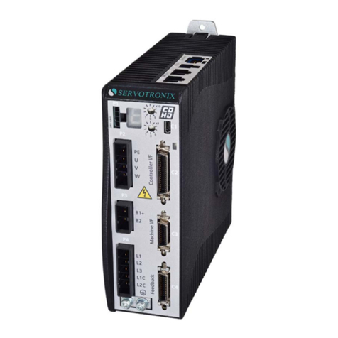
Servotronix CDHD Series Installation and operating instructions

CDHD Servo Drive
Pulse and Direction
Using Single-Ended Signal
Application Note
Document Revision: 1.0
Firmware Version: 1.3.2
Software Version: 1.3.1.1


Pulse and Direction Using Single-Ended Signal
Application Note 3
Revision History
Document
Revision
Date Remarks
1.0 Jan. 2013 Initial release
Firmware
Revision
Software (GUI)
Revision
1.3.2 1.3.1.1
Important Notice
© 2013 Servotronix Motion Control Ltd.
All rights reserved. No part of this work may be reproduced or transmitted in any
form or by any means without prior written permission of Servotronix Motion
Control Ltd.
Disclaimer
The information in this manual was accurate and reliable at the time of its
release. Servotronix Motion Control Ltd. reserves the right to change the
specifications of the product described in this manual without notice at any time.
Trademarks
All marks in this manual are the property of their respective owners.
Contact Information
Servotronix Motion Control Ltd.
21C Yagia Kapayim Street
Petach Tikva 49130 Israel
Tel: +972 (3) 927 3800
Fax: +972 (3) 922 8075
Website: www.servotronix.com
Email: info@servotronix.com
Customer Service
Servotronix is committed to delivering quality customer service and support for
all our products. Our goal is to provide our customers with the information and
resources so that they are available, without delay, if and when they are needed.
In order to serve in the most effective way, we recommend that you contact
your local sales representative for order status and delivery information, product
information and literature, and application and field technical assistance. If you
are unable to contact your local sales representative for any reason, please use
the most relevant of the contact details below:
For technical support, contact: tech.support@servotronix.com
To order products, contact: orders@servotronix.com
For all other inquiries regarding CDHD drives or other Servotronix products,
contact: customer.service@servotronix.com

Pulse and Direction Using Single-Ended Signal
4 Application Note

Pulse and Direction Using Single-Ended Signal
Application Note 5
Contents
1Overview ____________________________________________________7
2Wiring ______________________________________________________9
3Operation___________________________________________________11
Operation Sequence Overview...................................................................... 11
Preliminary Procedures ................................................................................ 11
Step 1 – Select Pulse and Direction............................................................... 11
Step 2 – Confirm Digital Inputs 5 and 6 are Set to Pulse and Direction.............. 12
Step 3 – Set Pulse and Direction Parameters.................................................. 13
Advance Settings........................................................................................ 14
Summary Screen ........................................................................................ 15

Pulse and Direction Using Single-Ended Signal
6 Application Note

Pulse and Direction Using Single-Ended Signal Overview
Application Note 7
1Overview
The CDHD’s Pulse and Direction Using Single-Ended Signal feature enables
the connection of PLCs with a 24 VDC single-end signal to the CDHD.
The following diagram shows how the feature is implemented.
CDHD
∑
Current
Loop M
+
-
PE
Load
ICMD
Current
Command
HDC
Pulse and
Direction
Position
Command
Feedback
PLC
PCMD
Position
Command
PFB
Gear Block
The drive accepts an input pulse train in which the rising edge of each pulse
increments (or decrements, depending on the direction) the external input
position counter (HWPEXT) of the drive by one position count. This counter value
is passed through a gearing block and becomes the position command for the
motor.
The position command is compared to the actual motor position (PFB) to
determine the position error (PE). The drive corrects the position error by
incrementing the motor to the commanded position.
Gearing sets up a relationship between the number of input pulses (HWPEXT
counts) and the position increments of the motor shaft (or actual motor position,
PFB). The rate at which position increments of the motor shaft (motor speed)
occur is determined by the gearing relationship and the line frequency of the
pulse train.
This application note describes the pulse following capability of the CDHD
system, using Operation Mode 4-Position Gear Mode. In this type of position
control, the drive is synchronized to a master input command signal in the form
of a pulse train.
The drive is configured to read this input signal as an pulse/direction counter.
The pulse train is geared to the incremental movement of the motor shaft
through the drive’s electronic gearing block.
The drive’s homing capabilities remain available in this configuration. For more
information on homing, refer to the CDHD User Manual.

Overview Pulse and Direction Using Single-Ended Signal
8 Application Note

Pulse and Direction Using Single-Ended Signal Wiring
Application Note 9
2Wiring
The Pulse signal is connected to CDHD fast digital input 5 – Controller I/F C2
pin 32.
The Direction signal is connected to CDHD fast digital input 6 – Controller I/F C2
pin 15.
Fast Digital Inputs Specifications
Signal Configurable Opto-Isolated
(compatible with sinking output)
Voltage 24 V
Max Input Current 10 mA
Propagation Delay Time 1 µs
The following diagram shows how to connect the PLC to the CDHD Controller IF
(C2) connector.
Connect the cable shield on the PLC side to any available shield connector.
Connect the cable shield on the CDHD side to the shell of the 36-pin
connector.
Note: The 24 VDC power supply must be provided by the user.

Wiring Pulse and Direction Using Single-Ended Signal
10 Application Note

Pulse and Direction Using Single-Ended Signal Operation
Application Note 11
3Operation
Note: The instructions in this document assume that you are familiar with
ServoStudio software.
Operation Sequence Overview
The operation sequence is comprised of the following steps.
1. Selecting Pulse and Direction motion.
2. Confirming that digital inputs 5 and 6 are set, respectively, to Pulse and to
Direction.
3. Setting the Pulse and Direction parameters.
Preliminary Procedures
1. Make sure the drive firmware version is 1.3.1 or later, and the ServoStudio
software version is 1.3.1.1 or later. If not, download and install these
versions.
If you are working with a later version, some software screens might appear
different than those shown in this document.
2. Run the ServoStudio Setup Wizard, and make sure motor setup is
successfully completed.
3. Run the ServoStudio Tuning Wizard, and make sure autotuning is
successfully completed.
Step 1 – Select Pulse and Direction
1. In ServoStudio, go to Tuning > Motion screen.
2. Select Operation Mode 4-Position Gear Mode.

Operation Pulse and Direction Using Single-Ended Signal
12 Application Note
3. In the Gear Input pane, select the option Controller I/F Opto-Isolated
and Pulse & Direction (P&D).
Step 2 – Confirm Digital Inputs 5 and 6 are Set to Pulse and Direction
1. Go to Drive Configuration > Digital IOs screen.
2. Make sure digital input 5 is set to 17-Pulse signal.
3. Make sure digital input 6 is set to 18-Direction signal.
Note: Selecting Controller I/F Opto-Isolated and Pulse & Direction (P&D) in
the Motion screen (Step 1) automatically sets the definitions for digital
inputs 5 and 6.

Pulse and Direction Using Single-Ended Signal Operation
Application Note 13
Step 3 – Set Pulse and Direction Parameters
1. Return to the Motion screen.
2. Select Multiplier.
Note that the schematic diagram reflects the setting.
It is strongly recommended that you enable Multiplier. This internal CDHD
feature is functional in pulse and direction operation, and typically improves
the Pulse and Direction reading.
3. Make sure the Gear mode is Engaged.
4. In the Ratio pane, set the External Encoder Resolution and Ratios.
The relationship between the number of incoming pulses and the motor
shaft movement is determined by the External Encoder Resolution, and the
Gear Ratio Multiplier and Divider (GEARI/GEARO).

Operation Pulse and Direction Using Single-Ended Signal
14 Application Note
For example: A PLC controller is programmed to provide 1024 line pulses
as an input command to a CDHD system in order to make the motor rotate
two revolutions. The settings are therefore:
External Encoder Resolution = 1024
Gear Ratio Multiplier = 2
Gear Ratio Divider = 1
Advance Settings
If you experience noise, you may want to improve HDC tuning.
For more information, refer to the HD Control Fine Tuning Application Note
(App_Note_HDC_Fine_Tuning_Rev_x.x.pdf)
Alternately, enable the Gear Filter Mode, and modify the parameter settings.
These settings have the effect of reducing the proportional gain of control.
It is recommended that you contact Technical Support for help in achieving
optimized settings.
Use the following table to record the values recommended by Technical Support,
and save for future reference.
Parameter Recommended
Setting
Gear Filter Depth
Gear Filter Velocity and Acceleration Depth
Gear Filter Acceleration Feedforward

Pulse and Direction Using Single-Ended Signal Operation
Application Note 15
Summary Screen
When the CDHD is ready for Pulse and Direction Using Single-Ended Signal
operation, the ServoStudio Motion screen settings will be as shown in the
following figure. Actual values may differ.

Other manuals for CDHD Series
1
This manual suits for next models
11
Table of contents
Other Servotronix Servo Drive manuals
Popular Servo Drive manuals by other brands

Delta Electronics
Delta Electronics ASDA-A Series quick start

Rockwell Automation
Rockwell Automation Allen-Bradley Kinetix 350 installation instructions

Panasonic
Panasonic MHMD042P1C Technical reference

Xinje
Xinje DS5C Series manual

Technosoft
Technosoft iPOS8015 BZ-CAT Technical reference

Lenze
Lenze 931 Series Communications manual