SET SET-2010 Parts list manual

1 of 10
www.smart-e-tech.com
SET-2010
Technical Description
Issue 02 13/04/2022
TECHNICAL DESCRIPTION
SET-2010
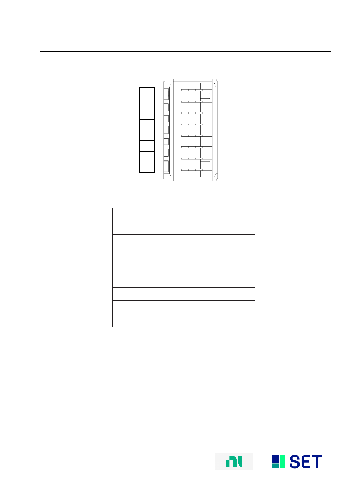
32 differential / 64 single ended channel routing card
This document 9040TDD0320 is a technical description of the SET-2010.
Note
Before you begin, complete the Software and Hardware installation procedures
applicable to your application.
Note
The guidelines in this document are specific to the SET-2010. The other
components in the system might not meet the same safety ratings. Refer to the
documentation of each component in the system to determine the safety and
EMC ratings for the entire system.
MORE INFORMATION ON OUR WEBSITE:
www.smart-e-tech.de/slsc

2 of 10
www.smart-e-tech.com
SET-2010
Technical Description
Issue 02 13/04/2022
Safety Guidelines
Caution Do not operate the SET-2010 in a manner not specified in this document. Product
misuse can result in a hazard. You can compromise the safety protection built into the product
if the product is damaged in any way. If the product is damaged, return it for repair.
Electromagnetic Compatibility Guidelines
This product was tested and complies with the regulatory requirements and limits for electromagnetic
compatibility (EMC). These requirements and limits provide reasonable protection against harmful
interference when the product is operated in the intended operational electromagnetic environment.
This product is intended for use in industrial locations. However, harmful interference may occur in
some installations, when the product is connected to a peripheral device or test object, or if the
product is used in residential or commercial areas. To minimize interference with radio and television
reception and prevent unacceptable performance degradation, install, and use this product in strict
accordance with the instructions in the product documentation.
Furthermore, any changes or modifications to the product not expressly approved by SET GmbH
could void your authority to operate it under your local regulatory rules.
Caution
To ensure the specified EMC performance, operate this product only with
shielded cables and accessories.
Caution
To ensure the specified EMC performance, the length of any cable attached to
connectors J1 and J2 must be no longer than 3 m (10 ft).

3 of 10
www.smart-e-tech.com
SET-2010
Technical Description
Issue 02 13/04/2022
Description
The SET-2010 Routing Card is a large-scale, high density switching matrix. With 64 single-ended or 32
differential channels. The SET-2010 provides exceptional signal routing capabilities in a small form
factor. Unlike traditional routing matrix cards, the SET-2010 is designed specifically for the challenges of
signal routing in HIL systems. To maximize customizability, the SET-2010 features two plug-in module
slots that can provide features such as line fault insertion and instrument connect. The base card
provides multiplexer functions for both front-panel IO and rear connectivity. Additionally, the SET-2010
Routing Card comes with a high current fault injection bus.
Circuitry
Note
The diagram only shows one channel for each connector J1/J2.
P0.x –P3.x
are connected with Slot 1 P0.x –P3.x
P4.x –P7.x
are connected with Slot 2 P0.x –P3.x

4 of 10
www.smart-e-tech.com
SET-2010
Technical Description
Issue 02 13/04/2022
Reference routing to the instrument bus
Reference routing to the fault bus
Note There is one common reference signal on the Routing Card which can be switched on
instrument and fault bus as well as on one reference (REF0/REF4) of each front connector.
Signal REFx/ENx:
0, 1, 2 & 3 are connected with Slot 1.
Signal REFx/ENx:
4, 5, 6 & 7 are connected with Slot 2.
All voltages are relative to GND unless otherwise noted.

5 of 10
www.smart-e-tech.com
SET-2010
Technical Description
Issue 02 13/04/2022
15
30
44
14
29
43
13
28
42
12
27
41
11
26
40
10
25
39
9
24
38
8
23
37
7
22
36
6
21
35 5
20
34
4
J1, J2 Pinout (Front)
J1 J2
Signal
Description
Px.y
Line y in Port x
DGND
Ground connection
NC
No connection
EN
Enable
REF
Reference
J1, J2 Connector Pin Assignments
15
30
44
14
29
43
13
28
42
12
27
41
11
26
40
10
25
39
9
24
38
8
23
37
7
22
36
6
21
35
5
20
34
4
19
33
3
18
32
2
17
31
1
16
P3.2+
P3.2-
P3.1+
P3.1-
P3.0+
P3.0-
EN3
EN2
P2.2+
P2.2-
P2.1+
P2.1-
P2.0+
P2.0-
NC
NC
P1.2+
P1.2-
P1.1+
P1.1-
P1.0+
P1.0-
EN1
EN0
P0.2+
P0.2-
P0.1+
P0.1-
P0.0+
P0.0-
P3.3+
P3.3-
REF3
REF2
P2.3+
P2.3-
NC
NC
P1.3+
P1.3-
REF1
REF0
P0.3+
P0.3-
15
30
44
14
29
43
13
28
42
12
27
41
11
26
40
10
25
39
9
24
38
8
23
37
7
22
36
6
21
35
5
20
34
4
19
33
3
18
32
2
17
31
1
16
P7.2+
P7.2-
P7.1+
P7.1-
P7.0+
P7.0-
EN7
EN6
P6.2+
P6.2-
P6.1+
P6.1-
P6.0+
P6.0-
NC
NC
P5.2+
P5.2-
P5.1+
P5.1-
P5.0+
P5.0-
EN5
EN4
P4.2+
P4.2-
P4.1+
P4.1-
P4.0+
P4.0-
P7.3+
P7.3-
REF7
REF6
P6.3+
P6.3-
NC
NC
P5.3+
P5.3-
REF5
REF4
P4.3+
P4.3-


7 of 10
www.smart-e-tech.com
SET-2010
Technical Description
Issue 02 13/04/2022
Row
e
d
c
b
a
1
P0.0- / P4.0-
P0.0+ / P4.0+
NC
P0.1- / P4.1-
P0.1+ / P4.1+
2
P0.2- / P4.2-
P0.2+ / P4.2+
NC
P0.3- / P4.3-
P0.3+ / P4.3+
3
GND
GND
GND
GND
GND
4
P1.0- / P5.0-
P1.0+ / P5.0+
NC
P1.1- / P5.1-
P1.1+ / P5.1+
5
P1.2- / P5.2-
P1.2+ / P5.2+
NC
P1.3- / P5.3-
P1.3+ / P5.3+
6
GND
GND
GND
GND
GND
7
P2.0- / P6.0-
P2.0+ / P6.0+
NC
P2.1- / P6.1-
P2.1+ / P6.1+
8
P2.2- / P6.2-
P2.2+ / P6.2+
NC
P2.3- / P6.3-
P2.3+ / P6.3+
9
DGND
DGND
DGND
DGND
DGND
10
P3.0- / P7.0-
P3.0+ / P7.0+
NC
P3.1- / P7.1-
P3.1+ / P7.1+
11
P3.2- / P7.2-
P3.2+ / P7.2+
NC
P3.3- / P7.3-
P3.3+ / P7.3+
12
NC
NC
NC
NC
NC
13
NC
NC
NC
NC
NC
14
NC
NC
NC
NC
NC
15
P4.0- / P0.0-
P4.0+ / P0.0+
NC
P4.1- / P0.1-
P4.1+ / P0.1+
16
P4.2- / P0.2-
P4.2+ / P0.2+
NC
P4.3- / P0.3-
P4.3+ / P0.3+
17
GND
GND
GND
GND
GND
18
P5.0- / P1.0-
P5.0+ / P1.0+
NC
P5.1- / P1.1-
P5.1+ / P1.1+
19
P5.2- / P1.2-
P5.2+ / P1.2+
NC
P5.3- / P1.3-
P5.3+ / P1.3+
20
DGND
DGND
DGND
DGND
DGND
21
P6.0- / P2.0-
P6.0+ / P2.0+
NC
P6.1- / P2.1-
P6.1+ / P2.1+
22
P6.2- / P2.2-
P6.2+ / P2.2+
NC
P6.3- / P2.3-
P6.3+ / P2.3+
23
GND
GND
GND
GND
GND
24
P7.0- / P3.0-
P7.0+ / P3.0+
NC
P7.1- / P3.1-
P7.1+ / P3.1+
25
P7.2- / P3.2-
P7.2+ / P3.2+
NC
P7.3- / P3.3-
P7.3+ / P3.3+
XJ2 Connector Pin Assignments
Signal
Description
Px.y
Line y in Port x
GND
Ground connection
NC
No connection
XJ2 Connector Signal Descriptions
8 of 10
www.smart-e-tech.com
SET-2010
Technical Description
Issue 02 13/04/2022
XJ3 Connector Pinout (Rear)
Pins
Signal
Slot1/Slot2
H
V1+
Instrument_0+
G
V1-
Instrument_0-
F
V2+
Instrument_1+
E
V2-
Instrument_1-
D
V3+
Fault_A
C
V3-
Fault_B
B
V4+
Fault_C
A
V4-
Fault_D
XJ3 Connector Pin Assignments
H
G
F
E
D
C
B
A

9 of 10
www.smart-e-tech.com
SET-2010
Technical Description
Issue 02 13/04/2022
LED Behavior
LED Name
LED Behavior
Definition of Behavior
PWR
Off
No power on board.
Solid green
Power good state.
RDY
Off
Module card is unpowered or reset active.
Solid green
Card is recognized by chassis and ready to communicate
Amber
Chassis is communicating.
Error Handling
LED Name
LED Behavior
Actions
PWR
Off
-Check chassis power supply.
-Check external power supply if used.
RDY
Off
-Check plugin module on board.
-Check fuse on board.
Hardware Specifications
Absolute Maximum Ratings
Property
Condition
Value
Comment
Max. Input Voltage
Any Pin
60 Vdc
Min. Input Voltage
Any Pin
-60 Vdc
Max. Switching Power
DC, Resistive load
60 W
Max. Current rating
1.5 A

10 of 10
www.smart-e-tech.com
SET-2010
Technical Description
Issue 02 13/04/2022
Technical Data
Property
Condition
Value
Comment
Update Time
10 ms
SLSC Commit CMD
duration
Max. Initial contact
Resistance
J1 -> XJ2
J2 -> XJ2
J1 -> J2
500 mΩ
Max. Electrical Lifetime
Expected
1 A, 30 Vdc resistive
Min 10^5 operations
Min. Electrical Lifetime
Expected
1.5 A, 30 Vdc resistive
Min 10^4 operations
Bandwidth
-3 dB, 50 ΩTermination
≤20 MHz
Physicals Characteristics
Property
Condition
Value
Comment
Module Dimensions
Excluding ejector
144.32 mm x 30.48 mm x
302 mm (H x W x D)
Standard SLSC card size
Front Panel Connector
2x female DB -44 high-
density D-Sub with 4-40
UNC screw lock
For mating connectors and
cables, see below
RTI Connector
2 mm hard metric per IEC
61076-101
Any RTI marked
Environmental
Property
Condition
Value
Comment
Operating Humidity
Relative, non-condensing
10%-90%
Storage Humidity
Relative, non-condensing
5%-95%
Operating temperature
Forced-air cooling from
chassis
0°C - 40°C
Storage Temperature
-40°C - 85°C
Maximum Altitude
2000 m
Table of contents
Other SET Network Hardware manuals


Popular Network Hardware manuals by other brands

PaloAlto Networks
PaloAlto Networks ION 3200 Hardware reference

No Wires Needed
No Wires Needed WB-S1100 user manual

Icy Box
Icy Box IB-NAS4220 manual

Interlogix
Interlogix TruVision NVR 20 user manual

Com-Power
Com-Power LI-1100C instruction manual

Universal Remote Control
Universal Remote Control MRX-4IR owner's manual


