Setcom MW 31 Series User manual

INSTALLATION AND USER GUIDE
Includes model numbers:
MWB15-31 BMW 2015 and later pg. 4
MWD13-31 Honda 1300 pg. 5
MWH-31 Harley-Davidson pg. 6
MWU-31(D13) Honda 1300 pg. 7
(Honda TX unit bracket,
universal PTT bracket)
MWU-31(H) H-D TX unit bracket, pg.8
universal PTT bracket
3019 Alvin DeVane Blvd.
Ste. 560
Austin, TX 78741
Phone: (650) 965-8020
CORPORATION
®
TECH SUPPORT: 650-965-8020 ext. 703
The MWx-31 Series is a motorcycle-handlebar-mounted
transmitter for remote PTT control of a portable radio
connected to a Setcom SWE-xx or SWA-xx Liberator
SuperMic.
(several models of SuperMic exist, the actual model
number depends on the portable radio model to be used)
The transmitter requires 12 VDC, supplied through a
fused connection, a 1 Amp fuse is recommended. Red
wire to +12V, Green wire to Ground.
Minimal power is drawn from the motorcycle but it is
recommended that it be supplied from a switched source,
such as the Accessory Lead.
The MWx-31 must be code-matched to the Supermic it is
to be used with. Details for this can be found on page 2 of
these instructions.
Various combinations of TX Unit and PTT switch
mounting brackets are available – the specific model
number indicates the typical motorcycle type the model
will be used on.
A complete system will include an MWx-31 Handlebar TX
Unit and brackets, an SW_-xx SuperMic, and a KE or KA
type of Helmet Kit (model number varies according to the
type of helmet).
Page 3 shows instructions on how to install the PTT
push-button assembly to a bracket.
Questions or technical issues? Please call:
8/9/19 SBHMWx-31 Series_UserGuide_REV_B.pdf Page of18

3019 Alvin DeVane Blvd.
Ste. 560
Austin, TX 78741
Phone: (650) 965-8020
Encoder on Liberator Mic (SW_-1___).
Accessible through the plugged hole on the
lower rear of the SuperMic enclosure.
Encoder on Liberator handlebar unit (MW_-31).
Accessible via the large threaded Nylon screw on
the side of the unit.
SWA-1M2A/L
S0619197313666
16-7002
Waterproof
hole plug
28-0014
21-2600
Nylon machine screw
16-0002
Rubber Gasket
A penny or nickel can be
used to remove and replace
the nylon screw for access
to the encoder setting of the
handlebar unit.
The handlebar unit is shipped with a flathead
screwdriver. This tool is for syncing the
handlebar unit to the SuperMic at installation and
then given to the end user to allow matching of
equipment over the life of the system.
The waterproof plug and nylon screw must
each be installed in the SuperMic and
handlebar transmitter respectively while in
service. Not installing these items allows for
water incursion and may void the warranty.
Portable-Only Wireless code-matching
Note the difference between
the two encoder dials.
The arrow indicators are
different as well as the
location of the codes.
SuperMic and Handlebar unit must also be on the same Code Block to match properly. Units are factory-set for Code Block
zero unless otherwise specified. A Code Block other than zero is indicated by an addition to the model number of the unit
(for example, MWH-31-C08 would indicate Code Block eight). Contact Setcom for more information. www.setcomcorp.com
CORPORATION
®
Page of28
SuperMic
Handlebar Unit
* Supermic and Handlebar unit must have matching settings *
MWx-31 Series_UserGuide_REV_B.pdf
3019 Alvin DeVane Blvd.
Ste. 560
Austin, TX 78741
Phone: (650) 965-8020
CORPORATION
®
TECH SUPPORT: 650-965-8020 ext. 703
Questions or technical issues? Please call:
Page of38
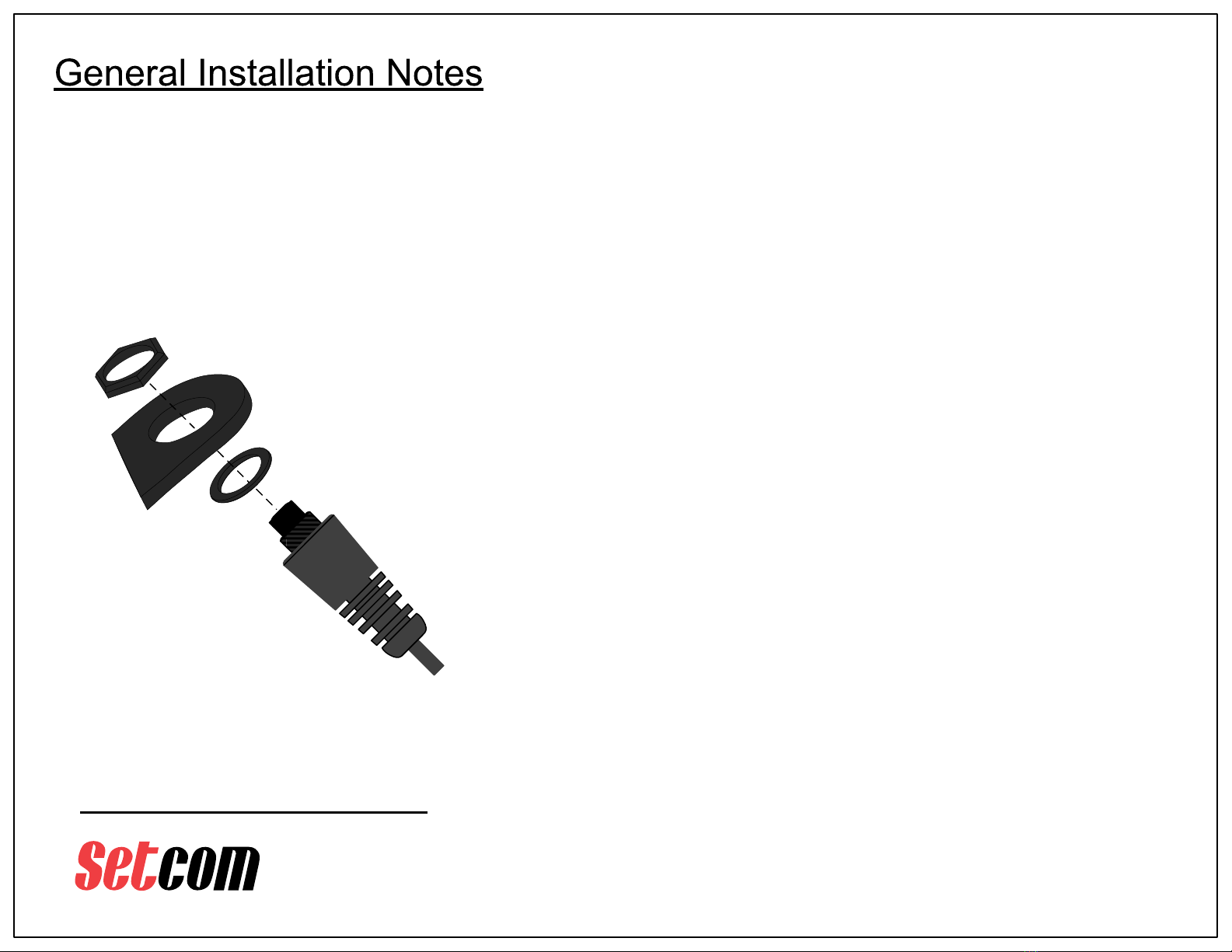
PTT Push-button Assembly Installation
(applies to all model numbers)
Use supplied hex nut
to secure pushbutton
switch to bracket
p/n 16-0001
Gasket
PTT
Subassembly
PTT
Bracket
Caution: Take care not to
scratch bracket when
securing hex nut.
The use of a non-marring
socket is recommended
Wiring:
The PTT pushbutton is usually hard-wired to the enclosure and only needs
to be mounted onto the included bracket (see diagram at left).
For the MWB15-31, installation only requires plugging a connector into the
motorcycle’s BCM unit.
DC Power wiring involves connecting the Green wire to a good ground point,
and the Red wire to a fused +12 VDC source (a 1A fuse is recommended).
The transmitter draws minimal power but it is recommended it be connected
to a switched DC source – Accessory power is typically used.
Checkout:
It is recommended to verify system operation before fastening down any
cabling or replacing any body panels that have been removed for access.
This requires a portable radio fitted with an SWE-xx or SWA-xx Supermic
and the cooperation of another radio operator for a radio transmission check.
Before completing the installation, it is important to make sure that any
cabling does not impair free movement of the handlebars, and that the
cabling will not be stretched, chafed, or broken by movement of the
handlebars or any other part of the motorcycle.
p/n HDWR 88
Hex Nut
MWx-31 Series_UserGuide_REV_B.pdf

AN 18-6000 SELF ADHERING CABLE TIE BASE WILL BE
USED AS A SECURING POINT FOR EXCESS CABLE LENGTH.
CLEAN THE SURFACE OF THE RADIO CABINET LID WHERE
THE CABLE TIE BASE WILL BE APPLIED. RUBBING
ALCOHOL IS SUGGESTED. ALLOW AREA TO DRY.
PEEL THE LINER FROM THE ADHESIVE PAD OF THE CABLE
TIE BASE AND PRESS CABLE TIE BASE ONTO RADIO
CABINET LID.
INSERT A 16-0001 CABLE TIE THROUGH THE CABLE TIE
BASE. LOOSELY COIL UP THE SERVICE LOOP OF CABLE
AND BIND IT TO THE CABLE TIE BASE.
CLIP EXCESS TAIL OF THE CABLE TIE.
CLEAN THE SURFACE WHERE THE MWB15-31 WILL BE
MOUNTED…. RUBBING ALCOHOL (70% ISOPROPYL ALCOHOL)
IS HIGHLY RECOMMENDED
IT IS RECOMMENDED TO SET THE CODE FOR THE UNIT
BEFORE MOUNTING IT.
CHOOSE A POSITION IN THE SHADED AREA TO MOUNT THE
MWB15-31 TO THE INNER LID OF THE RADIO CABINET.
NOTE THAT THE CONTENTS OF THE RADIO CABINET MUST
ALLOW CLEARANCE FOR THE MWB15-31 WHEN CLOSING
THE RADIO CABINET.
MWB15-31 – QTY 1
PACKAGE INCLUDES:
28-0014 – QTY 1 - DRIVER FOR CODE MATCHING
18-6001 – QTY 3 - CABLE TIES, 4"
18-6000 – QTY 1 – CABLE TIE BASE, SELF ADHESIVE
TWO SETS OF 3M DUAL LOCK HAVE
BEEN PRE-INSTALLED ONTO THE
REAR OF THE MWB15-31.
ONCE THE SELECTED AREA HAS
BEEN CLEANED AND DRIED, PEEL
THE THIN LINERS FROM THE DUAL
LOCK AND PLACE MWB15-31 UNIT
INTO POSITION ON THE RADIO
CABINET LID.
APPLY TO SURFACE WITH FIRM
EVEN PRESSURE.
1
2
34
5
10/26/2018 MCS
USE THE REMAINING TWO CABLE TIES TO SECURE
THE CABLE RUN TO THE EXISTING HARNESS.
BE SURE TO ALLOW ENOUGH SLACK SO THAT THE
RADIO CABINET CAN FULLY OPEN AS WELL AS CLOSE
COMPLETELY WITHOUT CAUSING ANY DAMAGE TO
THE CABLE OR CONNECTOR ASSEMBLY.
6
CONNECT THE 8-PIN CONNECTOR
TO HEADER #6
HELMET HEADSET INTERFACE
Page of48
3019 Alvin DeVane Blvd.
Ste. 560
Austin, TX 78741
Phone: (650) 965-8020
www.setcomcorp.com
CORPORATION
®
MWx-31 Series_UserGuide_REV_B.pdf

3019 Alvin DeVane Blvd.
Ste. 560
Austin, TX 78741
Phone: (650) 965-8020
CORPORATION
®
TECH SUPPORT: 650-965-8020 ext. 703
Questions or technical issues? Please call:
Page of58
TX Unit mounted on 14-0076 bracket
Uses HDWR 51 Kit to install
PTT Assembly mounted on
14-0072B bracket (see pg. 3)
Uses HDWR 50 Kit to install
Setcom
supplied
standoffs Remove and
discard
original
screws
Setcom
supplied
posi-drive
screws
Left handlebar
control cluster
For this version the TX unit is
installed in front of the clutch
hydraulic reservoir on the left
handlebar.
The PTT bracket is installed under
the control cluster on the left
handlebar.
MWx-31 Series_UserGuide_REV_B.pdf
3019 Alvin DeVane Blvd.
Ste. 560
Austin, TX 78741
Phone: (650) 965-8020
CORPORATION
®
TECH SUPPORT: 650-965-8020 ext. 703
Questions or technical issues? Please call:
Page of68
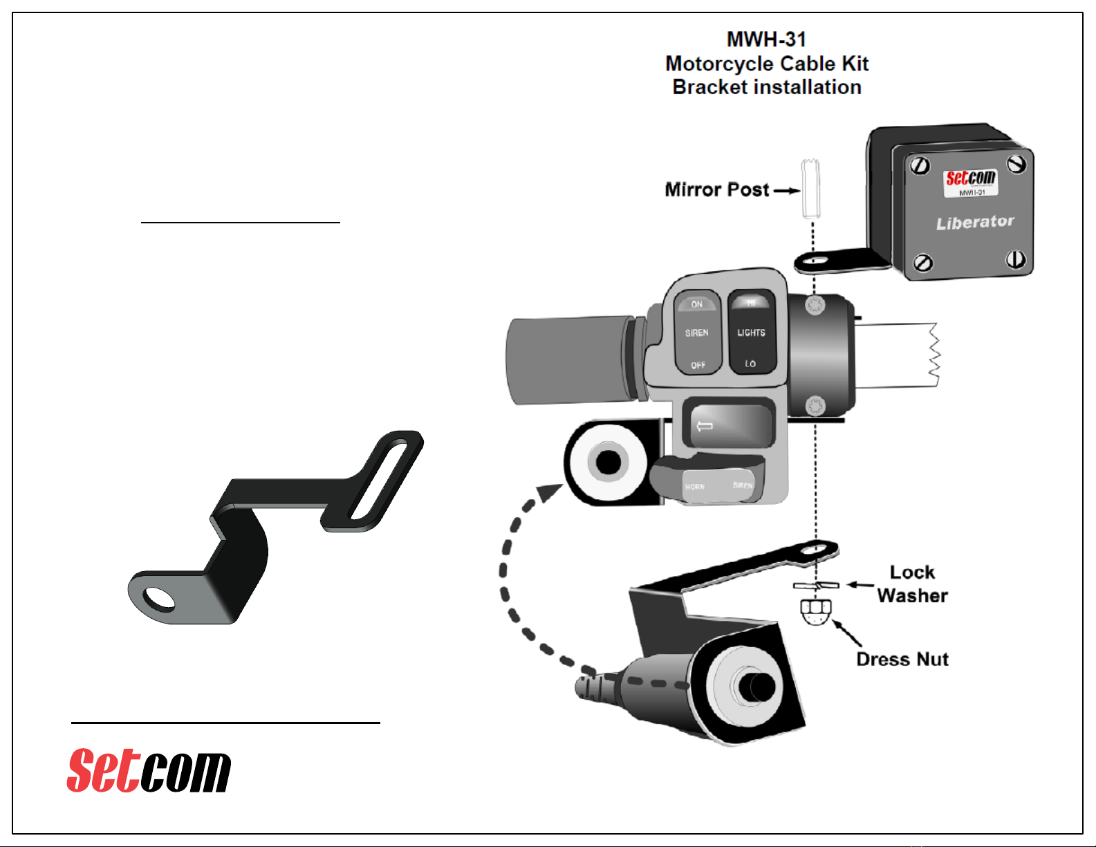
MWH-31 Installation
PTT Assembly mounted on
14-0048 bracket (see pg. 3)
TX Unit mounted on
14-0085 bracket
For Harley-Davidson motorcycles the installation
uses the left mirror post as the mounting location.
The most recent version of 14-0048
bracket is shown here. It has been
updated with a sliding slot for
mounting, to allow more flexibility in
positioning the PTT Assembly.
(older version of PTT bracket
shown in this diagram)
MWx-31 Series_UserGuide_REV_B.pdf
3019 Alvin DeVane Blvd.
Ste. 560
Austin, TX 78741
Phone: (650) 965-8020
CORPORATION
®
TECH SUPPORT: 650-965-8020 ext. 703
Questions or technical issues? Please call:
Page of78
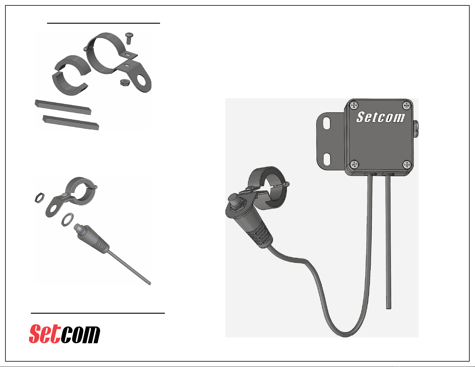
MWU-31 (D13) Installation
14-0083 Universal Bracket for .500" switch
Shown with HDWR 130 Universal Bracket hardware
kit including hard rubber inserts to accommodate
various diameters of mounting locations
Mounting Pushbutton PTT switch
to Universal Bracket (recommend
use of non-marring tool)
The MWU-31 (D13) is for semi-custom installations where
standardized brackets may not be applicable.
The Transmitter Unit is to be mounted in a convenient accessible
location on the handlebar assembly or fairing.
The Pushbutton PTT switch assembly is to be installed on the left
side grip. The inserts provided allow fitment to a variety of grip
diameters.
Transmitter Unit mounted
on 14-0076 Bracket
Pushbutton
PTT Switch
DC Power
Cable
MWx-31 Series_UserGuide_REV_B.pdf

3019 Alvin DeVane Blvd.
Ste. 560
Austin, TX 78741
Phone: (650) 965-8020
CORPORATION
®
TECH SUPPORT: 650-965-8020 ext. 703
Questions or technical issues? Please call:
Page of88
MWU-31 (H) Installation
14-0083 Universal Bracket for .500" switch
Shown with HDWR 130 Universal Bracket hardware
kit including hard rubber inserts to accommodate
various diameters of mounting locations
Mounting Pushbutton PTT switch
to Universal Bracket (recommend
use of non-marring tool)
The MWU-31 (H) is for semi-custom installations where standardized
brackets may not be applicable.
The Transmitter Unit is to be mounted on the left mirror post in the
same way as the standard MWH-31.
The Pushbutton PTT switch assembly is to be installed on the left
side grip. The inserts provided allow fitment to a variety of grip
diameters.
DC Power
Cable
Pushbutton
PTT Switch
Cable
MWx-31 Series_UserGuide_REV_B.pdf
This manual suits for next models
5
Other Setcom Motorcycle Accessories manuals

Popular Motorcycle Accessories manuals by other brands


Parkside
Parkside PSHL 2 B1 Operation and safety notes translation of the original instructions

Memphis Shades
Memphis Shades 2320-0067 Mounting instructions

Memphis Shades
Memphis Shades MEM-9890 Mounting instructions

Pandora
Pandora SMART MOTO V2 user manual

PerTronix
PerTronix IGNITOR 1247P6 installation instructions

PUIG
PUIG 9717 quick start guide

HealTech Electronics
HealTech Electronics iLogger easy Supplementary manual

Schweißkraft
Schweißkraft VarioProtect PANORAMA-W S-TC operating instructions

VVCAR
VVCAR MT55 user manual

hepco & becker
hepco & becker 6303528 00 01 quick start guide

Stage6
Stage6 RIEJU MRT Assembly instructions

Sealey
Sealey VS779.V3 instructions