Pandora SMART MOTO V2 User manual

Product is in conformity with Electromagnetic Compatibility
Directive EMC 2004/108/EC and R&TTE Directive 1999/5/EC
Pandora would like to thank you for
choosing our service-security system
Pandora Smart Moto v2
Pandora Smart Moto v2 is a security-service system specially designed for motorcycles.
It is a complex engineering solution, which includes security system, telemetry, remote and
automatic engine start and various service options.
When building the Pandora Smart Moto v2 we were using the most up-to-date electronics from
world’s best manufacturers. The device is built using high-precision mounting and control machinery,
thus we guarantee highest possible quality, reliability and stable technical characteristics for the whole
operation period.
The system is built for your convenience: its ergonomic, reliable, has the highest security and service
characteristics, 3 years warranty. We are happy to provide any support we can – feel free to use our
online support.
This device has limited external factors resistance. It should not be operated in temperatures outside -40 to +85° C range.
Our web site: www.pandorainfo.com

2PANDORA SMART MOTO V2
Table of contents
General information 4
System set 4
Read before using 5
PIN-codes of the system 6
System modules layout 6
Owner’s personal card 7
External VALET button 7
Base unit 8
System signals 9
System functions and modes 11
Security mode 11
Owner authorization devices and functions 13
Checking the number of paired devices 14
Immobilizer radio tag 15
Functions of the button 15
Indication of the SEND LED 16
Replacing a battery of the tag 16
Updating firmware of the tag 16
Control the system by a phone 17
Changing settings via a phone 19
System installation 21
General installation requirements 21
Wiring description 22
Wiring diagram 24

3
USER MANUAL
Online service and mobile applications 26
Control the system 29
Arming 29
Disarming 30
PANIC mode 31
Vehicle search function 31
Service mode 32
Control of the system in case of emergency 33
Emergency disarming 34
Temporary deactivation of anti-theft functions 34
Programming the systems 36
Entering/Exiting programming mode 37
Programming table 38
Additional devices 42
Warranty obligations 44
Installation certificate 47
Acceptance certificate 48
Warranty card 48

4PANDORA SMART MOTO V2
GENERAL INFORMATION
System set
1. User manual 1
2. Owner’s personal card 1
3. Radio tag BT-760 2
4. Base unit 1
5. External VALET button 1
6. External temperature sensor 1
7. Reed sensor 2
8. Blocking relay 1
9. Piezo siren PS-330 1
10. Wires 1
11. Fastening kit 1
12. Packaging 1
!The manufacTurer reserves The righT To change The sysTem seT and consTrucTion of The producT To improve iTs
Technological and operaTional parameTers wiThouT anoTificaTion.

5
USER MANUAL
Read before using
Carefully read this manual before starting installation and using the security-service system. Pay
attention to text marked with !
! The securiTy and TelemeTric sysTem is acomplex Technical producT. sysTem insTallaTion and configuraTion musT be
carried ouT only by askilled professional.
!feaTures and sysTem modes, conTrol of The vehicles zones depends on The Type of connecTion and sysTem seTTings,
original vehicle operaTion logic and Trim.
!The sysTem seT includes The “owner’spersonal card”. This card conTains informaTion under aproTecTive layer ThaT
is inTended only for The owner of The sysTem. make sure ThaT The proTecTive layer on The owner’splasTic card is
inTacT afTer The insTallaTion of The sysTem. read The “owner’spersonal card” secTion of This manual before erasing
The proTecTive layer.
!when sysTem insTallaTion is finished:
• check The sysTem operaTion and funcTions wiTh aspecialisT.
• werecommend ThaT you mark each working funcTion wiTh asign in The “conTrol The sysTem” secTion.
• check ThaT The “insTallaTion cerTificaTe” and “warranTy card” are filled ouT. These documenTs may be required for
conTacTing The cusTomer supporT.
• ask an insTaller To mark The layouT of The sysTem componenTs on The diagram. This informaTion may be required for
diagnosTic/configuring or emergency deacTivaTion of The sysTem.
• werecommend ThaT you change The defaulT value of The pin-codes of The sysTem. you can wriTe down The changed
pin-codes in The “pin-codes of The sysTem” secTion.

6PANDORA SMART MOTO V2
PIN-codes of the system
The “Secret PIN-code“
(is written on the “Owner’s personal card”)
The “Service PIN-code”
(default value is 1-1-1-1)
The “Guest PIN-code”
(default value is 1-2-3-4)
The “Immobilizer PIN-code”
(is used for the Validator (pin-to-drive) function)
!iTis recommended ThaT you will wriTe down The changed or creaTed values of all pin-codes. eliminaTe Third-parTy
access To This informaTion.
System modules layout
CANNOT BE CHANGED
External VALET button
(VALET button via CAN)
Base unit
Temperature sensor
Siren
Circuit being blocked
1
2
3
4
5
6
7

7
USER MANUAL
+7-9хх-ххх-хх-хх
1070000000 / Y34aC4vJ
2-2-2-2
LOGIN / PASS
PIN PHONE NUMBER
Owner’s personal card
! erase The proTecTive layer carefully. donoT use any sharp objecTs
To avoid damaging of hidden informaTion under The proTecTive layer.
The owner’s personal card contains private information
under a protective layer:
• PIN (the “Secret PIN-code”) is a 4-digit number. This code can
be used to disarm the system and to deactivate immobilizer
functions and to activate service mode. It can be also used to
enter programming mode.
• LOGIN is a 10-digit number. This information is used to add
the system to the online service and mobile applications.
• PASS contains 8 characters and can consist of digits, lower
and upper case letters). This information is used to add the
system to the online service and mobile applications.
• Phone number is a phone number of the SIM-card installed
in the base unit.
External VALET button
An external VALET button with a three-color status LED indicator
is placed inside a vehicle (see the system modules layout). The
button is used for programing the system, arming/disarming,
activating/deactivating immobilizer mode.

8PANDORA SMART MOTO V2
Base unit
Built-in GSM modem (2G/LBS) – provides a connection with our online-service pandora-on.com
and mobile applications (Pandora Online/Pandora Pro), allows to control the system by a phone using
DTMF-commands, voice and SMS notifications, LBS-coordinates (only by DTMF –command) automatic
date and time detection
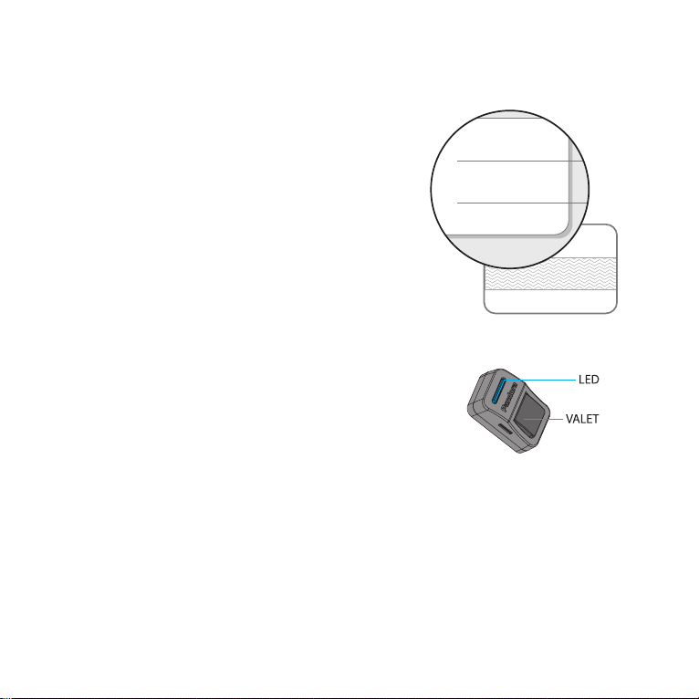
Built-in nano-SIM port is used to work with the built-in GSM modem. The phone number of the
SIM-card installed in the base unit is written on the Owner’s card.
!The sim-card can be changed. The sim-card should be replaced and The following seTTings should be performed
only by aspecialisT
Built-in GPS/GLONASS-receiver is designed to determine current location and to automatically
determine UTS date and time.
2.4GHz radio channel, Bluetooth 4.2 protocol (BT4.2) - supports additional Bluetooth devices
(see the “Additional devices”section), including a mobile phone.
Built-in 3D accelerometer is used to detect shock/motion/tilt including 2 separate zones of shock
sensor (alarm and warning), the system allows to adjust sensitivity of each zone, to use data from the
accelerometer to block the engine and close the central lock on movement.
Temperature sensors allow the system to measure temperature of different zones: outside
temperature – built in sensor of the main unit, engine temperature – external temperature sensor.
The system setting allow you to reassign sensor to different zones and use information from
external additional devices (see the “Additional devices”section).
Built-in battery to notify an owner in case of power disconnection in armed mode. The battery will
be charged automatically when engine is running.
Built-in micro-USB port – update and configuration of the system using a PC and Pandora Alarm
Studio.

9
USER MANUAL
System signals
SOUND AND LIGHT SIGNALIZATION
SIGNALS DESCRIPTION
1х /1х Arming
2х /2х Disarming
1х Enabling Service mode
2х Disabling Service mode
3х / 3 times Battery in a radio tag is discharged warning (when turn on ignition)
4х /4 times There is no any authorization device warning (when turn on ignition)
5x /5x Car search function
30 sec. /30 sec. Alarm, PANIC mode
3х /1х Warning level of a sensor is triggerd
4х /4х Sensors were triggered’signal when disarming /
‘Sensors are triggered”signal when arming

10 PANDORA SMART MOTO V2
LED INDICATOR SIGNALS
SIGNALS DESCRIPTION
THE SYSTEM IS ARMED
Short red ashes System is armed
Short green ashes System is armed (an authorization device is in the coverage zone)
Fast red ashes Alarm
THE SYSTEM IS DISARMED
Faded System is disarmed
Red System is preparing for automatic or delayed arming
Green
(when ignition is on) System is in service mode
Green ashes
(when switching on the
ignition)
Conrms the number of paired radio tags
Red ash
(when switching on the
ignition)
Conrms a paired mobile device
WHEN ENTERING THE“SECRET PIN-CODE”OR THE“SERVICE PIN-CODE”
Orange ash Conrms a VALET button press
Short red ash Conrms a digit input
PIN-code is incorrect
Red and green ashes Conrms correct PIN code

11
USER MANUAL
SYSTEM FUNCTIONS AND MODES
Security mode
The system confirms arming with 1х sound and 1х light signals. When the system is armed,
the system monitors security zones with separated warning and alarm level of triggering:
• Warning mode - this mode activates when there is a slight impact on the shock sensor or additional
senor. It is accompanied with1х light and 3х sound signals;
• Alarm mode - this mode activates when a sensor or one of the security zones is triggered. It is
accompanied with 30 sec. light and 30 sec. sound signals, he alarm signals can be canceled
by an arming or disarming command.
• If one of the security zones is triggered the system:
• records this event in its non-volatile memory;
• activates the alarm or warning mode;
• informs an owner by all available means;
• blocks the engine (in accordance with the settings and connections).
• If one of the security zones is opened at the moment of arming, the system will produce 4х
sound and 4х light warning signals.
If one of the security zones fails, the system will forcibly turn off this zone. If a switch triggers
more than 9 times in a row, it will be disabled until the next arming. The shock/tilt/motion sensor is
temporarily deactivated (15 sec.) if it has been triggered more than 3 times in a row.
The system confirms disarming with 2х sound and 2х light signals. The system deactivate
engine blocking (if the immobilizer function and additional blocking are not used). If there were alarm
events during the armed period, the system will produce 4х sound and 4х light warning
signals. The system continues to display all zones when it is disarmed, but the information is not saved
in the memory.

12 PANDORA SMART MOTO V2
VEHICLE/SYSTEM ZONES CONTROLLED ZONES SECURITY ZONES
NOTIFICATIONS
Voice SMS Push
External temperature
Engine temperature
On-board voltage
Shock sensor (alarm)
Shock sensor (warning)
Tilt sensor (alarm)
Motion sensor (alarm)
Ignition (alarm)
Brake (alarm)
Clutch (alarm)
Trunk (alarm)
Additional sensor (alarm)
Additional sensor (warning)

13
USER MANUAL
Owner authorization devices and functions
Authorization devices
Authorization devices are Bluetooth devices paired with the system (radio tags, remote control D030,
mobile phone with the app). The devices are used to recognize an owner in the radio coverage zone
of the base unit to arm/disarm the system (Hands Free mode) and to implement immobilizer or Anti-
Hi-Jack functions.
!werecommend To insTall The beeper if you use auThorizaTion devices
Arming/Disarming by clutch lever
You can arm/disarm the system by a clutch lever if an authorization device is in the coverage zone.
!This mode is enabled by defaulT. iTis required To make addiTional connecTions for This mode.
Hands Free arming/disarming
This mode is used for automatic arming/disarming when an owner with an authorization device is
distancing or approaching a vehicle.
!This mode is disabled by defaulT. iTis required To make addiTional seTTings using The mobile applicaTion or pandora
alarm sTudio To use This mode. quick access commands To manage hands free mode: 223* - acTivaTe hands free
arming, 224* - acTivaTe hands free disarming, 222* - deacTivaTe all hands free modes.
Immobilizer mode
This mode is used to recognize an owner using authorization devices when the system is disarmed.
When turning on the ignition, the base unit performs a search for authorization devices in the radio
coverage zone. If there is no any authorization device in the radio coverage zone, the system will block
the engine. Engine blocking will occur immediately or at the time a motion sensor detects movement,
it depends on the system settings. When an authorization device appears in the coverage zone, the
system will exit blocking mode and will continue to work in normal mode.
!This mode is enabled by defaulT. iTis required To make addiTional connecTions for This mode.

14 PANDORA SMART MOTO V2
Multi-button code immobilizer (pin-to-drive)
Multi-button code immobilizer (pin-to-drive) is a function that allows disarming, disabling blocking and
controlling service mode and time channels using original vehicle controls (button, lever or pedal) and
a pre-programmed PIN-code (the “Immobilizer PIN-code”).
AN EXAMPLE OF USING THE FUNCTION
• Turn on the ignition to disable engine blocking or enable service mode, turning on the ignition is not
required if you want to disarm the system or control time channels.
• Enter the “Immobilizer PIN-code”. Press a programmed button/lever/pedal the number of times
equals to the first digit. Pauses between presses should not exceed 1 second. More than 1 second
pause will be interpreted as the start of the next digit input. The immobilizer code can consist max
of 4 digits from 1 to 9.
• The system will confirm the correct input by a sound signal of the beeper and a programmed
• function will be performed.
!This mode is disabled by defaulT. This mode can be seT only by aprofessional specialisT
Checking the number of paired devices
The number of paired radio tags/mobile device can be checked by the number of flashes of the LED
indicator. The number of tags/mobile device can be checked when switching on the ignition (the
system must be disarmed). The number of green flashes will indicate the number of paired radio tags, a
following red flash will indicate a paired mobile device.
You can also check the number of paired radio tags/mobile device by taking off and putting back on
battery terminal. The system will emit short sound signals from a siren :
• First series of the siren signals – indicates the number of paired radio tags;
• The second long signal after a pause of 2 seconds indicates a paired mobile devices.

15
USER MANUAL
IMMOBILIZER RADIO TAG
A radio tag is a device used to control a vehicle/system. The tag is also used as an authorization device
for “Immobilizer/Anti-Hijack/HandsFree” modes. It works in the Bluetooth coverage zone. The radio tag
has:
- 2.4GHz frequency, BLUETOOTH 4.2 LOW ENERGY protocol
- control button
SEND - LED indicator
CR 2032 - Battery
3D - Motion sensor
!avoid moisTure on The radio Tag. donoT place The radio Tag near magneTs or
producTs wiTh self-magneTic fields
Functions of the button
ACTION FUNCTION
- Short press when ignition is off Arm/disarm
- 2 seconds (system is disarmed) Change the “Main owner’s phone number”
- Press and hold for 3 sec when
ignition is on Activate/deactivate Service mode
- 6 Press and hold for 6 sec. Pair a tag with the base unit
- Press and hold for 10 sec. Firmware update
SEND
3D

16 PANDORA SMART MOTO V2
Indication of the SEND LED
SIGNALS DESCRIPTION
1 ash Arm/disarm
Conrmation of arming
Low battery level (when installing a battery)
2 ashes Conrmation of disarming
3 ashes High battery level (when installing a battery)
Faded
Constant light Battery is discharged
(when installing a battery, when the button is pressed)
Replacing a battery of the tag
Carefully open the cover of the tag’s battery
compartment. Extract discharged battery and insert a
new one keeping in mind the correct polarity. Replacing
a battery will not cause a loss of tag code information, as
authorization data is stored in the non-volatile memory
of the MCU. Carefully close the cover of the tag’s battery
compartment. All elements of construction should be
rigidly locked in places. If it is so, the tag can be operated
as usually.
Updating rmware of the tag
• Download the Pandora BT application (for Android or iOS devices equipped with a Bluetooth 4.0 Low
Energy or higher module).
• Open the mobile app Pandora BT.
• Press and hold the button of the radio tag until the 10th flash of the «SEND» indicator, then
release the button.
• Select the found device and select one of the update option: FILE MANAGER – firmware will be
uploaded from the phone storage (only for Android). INTERNET – firmware will be uploaded by an
internet connection.
Open here

17
USER MANUAL
CONTROL THE SYSTEM BY A PHONE
! for The correcT operaTion of The gsm funcTions, an owner should moniTor The sTaTus/balance of The sim card
insTalled in The sysTem. ifThe sim card is blocked or defecTive, gsm funcTions of The sysTem will be unavailable.
Call the system’s phone number. When it answers, enter a command code
!*iTis required To enTer The “secreT pin-code” afTer dialing acommand
Voice help
The system has a voice help menu. During a voice call to the system, dial 9* and listen to the
information about system control commands.
To end the session, hang up the phone.
Repeat the last message
To repeat any message, press * during a voice call to the system.
Request current coordinates
1. Call the system number. Wait for the answer.
1
10
00
0*
*
5
5
1
1*
*
3
33
33
3*
*
5
50
00
0*
*
7
75
53
3*
*
#
#
9
9*
*
*
*
0
0
0
0*
*
0
0
1
1*
*
1
1*
*
0
0*
*
9
99
98
8*
*Отключение радиометки*
2
25
58
8*
*
6
66
66
6*
*
9
99
99
9*
*
2
22
22
2*
*
2
22
23
3*
*
2
22
24
4*
*
2
29
97
7*
*
5
55
51
1*
*
5
55
52
2*
*
8
88
88
8*
*
4
45
56
6*
*
6
65
54
4*
*
Return to previous menu
Repeat the last message
Arming
Disarming
Silent arming
Silent disarming
Help
Tow truck mode
Request GSM account balance
Switch on add. function using F via CAN
Request current coordinates
Force connection to the server
Switch on additional channel
Switch off additional channel
System information
Disable Hands Free mode
Enable Hands Free arming
Enable Hands Free disarming
End call
Enable service mode (see description below)*
Disable service mode
Enable engine blocking
Disable engine blocking*
Enable authorization devices

18 PANDORA SMART MOTO V2
2. Dial 500*.
3. The system will confirm:‘Current coordinates are sent via text message’and will send text message
with coordinates and a web link to a map to your phone.
To end the session, hang up the phone..
Request GSM balance
1. Call the system number. Wait for the answer.
2. Dial 100*.
3. The system will confirm: ‘Balance information is sent via text message’and will send text message
with account balance information to your phone.
To end the session, hang up the phone
Tow truck mode
This mode is intended for car transportation with preservation of arming function. Tow truck mode
can be activated only when the system is armed, it will be deactivated automatically when disarming.
1.Call the system number. If the system is in PANIC mode, receive an emergency call. Wait for the
answer.
2.Dial 15* , to enable the “Tow truck” mode, the system will disable motion, shock and tilt sensors.
To end the session, hung up the phone.
3.To disable this mode, disarm the system.
Activating/Deactivating engine blocking
You can block a car engine using any phone. The engine will remain blocked until phone command
‘Unlock engine’will be sent and the “Secret PIN-code”will be entered. This blocking cannot be disabled
using a remote control or VALET button.
1.Call the system number and wait for the answer.
2.Dial 666* to block an engine or 999* to unlock it (after dialing 999* you should enter the“Secret
PIN code”that is located on the owner’s card).
! all oTher commands can be enTered in The same manner.

19
Changing settings via a phone
System’s number -> «#»
5
5
*
*
Set up date
Set up time
1
1
*
*
2
2
*
*
Phone
number settings
Owner's number -> #
Additional owner's number -> #
Second additional owner's
number -> #
Account balance inquiry number -> #
1
1
*
*
1
1
*
*
2
2
*
*
3
3
*
*
4
4
*
*
Sensor
sensitivity settings
Settings of the warning level of the
shock sensor sensitivity
Settings of the alarm level of the
shock sensor sensitivity
Settings of the motion sensor
sensitivity
1
1
*
*
2
2
*
*
3
3
*
*
4
4
*
*
Settings of the tilt sensor sensitivity
Settings of the warning level of the
supplementary sensor sensitivity
5
5
*
*
Settings of the alarm level of the
supplementary sensor sensitivity
6
6
*
*
7
7
*
*
Settings
of the voice calls
Voice calls on alarm
Voice calls on triggering warning
level of the sensors
Voice calls on engine start
Voice calls on engine stop
1
1
*
*
2
2
*
*
3
3
*
*
4
4
*
*
Voice calls on restoring GSM
connection
Voice calls on disarming
5
5
*
*
6
6
*
*
Voice calls on entering
programming mode
Voice calls when radio relay
connection is lost
7
7
*
*
8
8
*
*
Voice calls when on-board voltage
is low
9
9
*
*
Voice calls on accident
0
0
*
*
2
2
*
*
Settings
of the text messages
Text messages on alarm
Text messages on triggering warning
level of the sensors
Text messages on engine start
Text messages on engine stop
Text messages on restoring GSM
connection
Text messages on disarming
1
1
*
*
2
2
*
*
3
3
*
*
4
4
*
*
5
5
*
*
6
6
*
*
Text messages on entering
programming mode
Text messages when radio relay
connection is lost
7
7
*
*
8
8
*
*
Text messages when on-board
voltage is low
9
9
*
*
0
0
*
*
3
3
*
*
Additional
settings
Changing guest PIN-code
Entering as guest
1
1
*
*
2
2
*
*
Set threshold voltage for sending
text message
5
5
*
*
5
5
*
*
Settings
of saving mode
GSM connection
Money saving mode of the GSM
connection
Voice calls in roaming service
1
1
*
*
2
2
*
*
3
3
*
*
8
8
*
*
Current time
and date settings
9
9
*
*
Text messages on accident

20 PANDORA SMART MOTO V2
Disarm the system, call the system number, wait for the answer, switch on the ignition for 1-3
seconds (but no more than 5 seconds), then switch it off. The system will enter the settings mode.
An example of changing the owner’s system number:
1.Enter the setting menu via a phone according to the instruction above;
2.Dial DTMF command 1*(phone number settings) and 1*(owner’s system number);
3.Enter new owner’s number in the format *XXXXXXXXXXX # (the system recognizes ‘*’ as ‘+’);
4. To confirm, dial 1*.
! There are 3 ways To change main owner’sphone number:
1. via aphone, using dTmf commands seTTings mode.
2. using radio Tags: Turn on The igniTion when The sysTem is disarmed and call The sysTem phone number. waiT for The
answer, dial The “guesT pin-code” (defaulT value is 1-2-3-4) if you are calling noT from The main owner’snumber,
Then press and hold The buTTon on The radio Tag for 2 seconds (unTil The second flash of The send indicaTor).
release The buTTon, The sysTem will recognize The incoming phone number as The “main owner’sphone number.
3. using The pandora alarm sTudio or pandora bT applicaTions.
Table of contents
Other Pandora Motorcycle Accessories manuals