4 VarioProtect PANORAMA - Serie | Version 2. 2 | EN
Safety
Tips and recommendations
It is necessary to observe the safety notes written in
these operating instructions in order to reduce the risk of
personal injuries and damages to property.
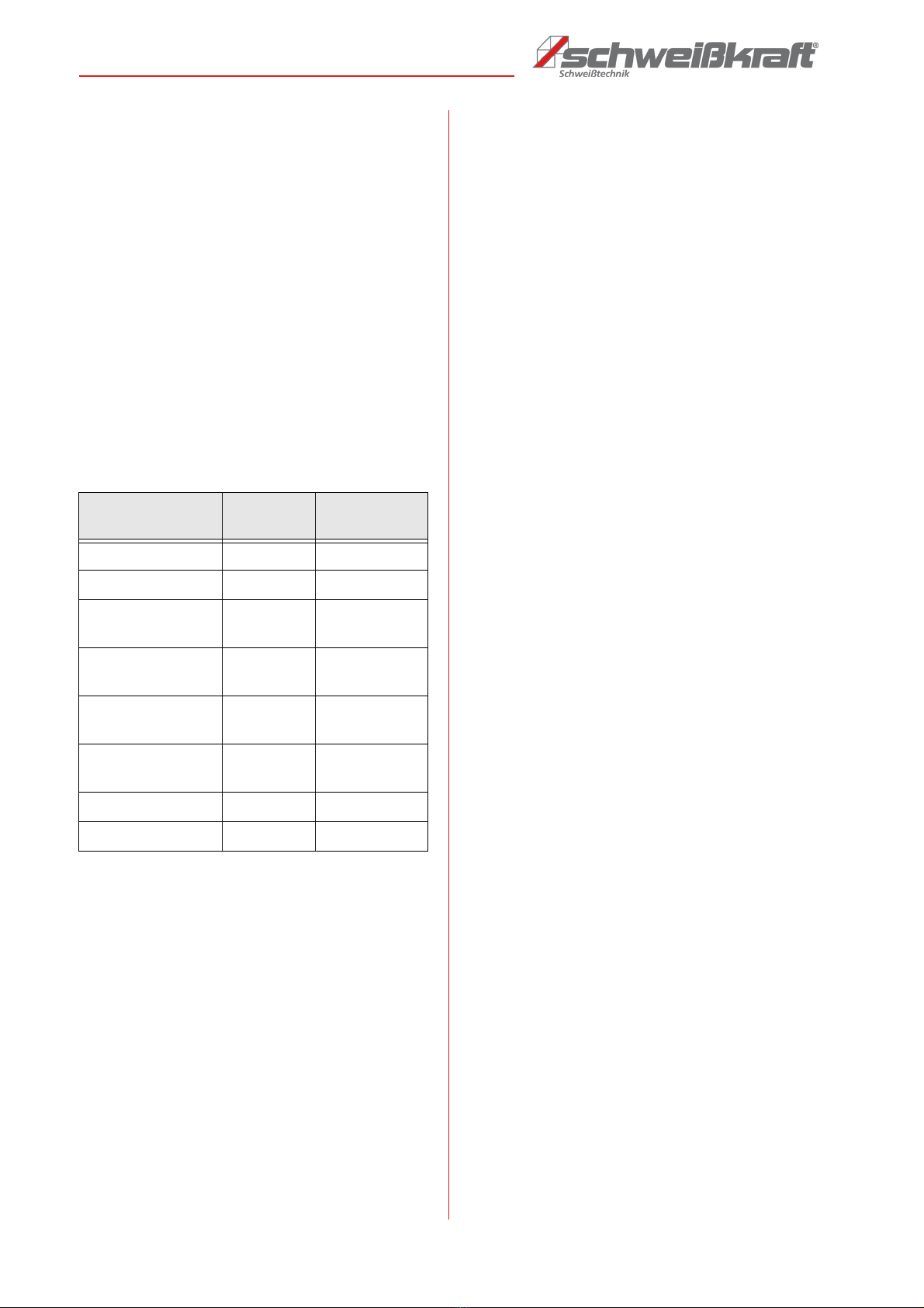
2.2 Safety regulations
- Check the Automatic Welding Helmet for externally
visible damage and defects before putting it into
operation.
- Repair any defects and damage immediately.
- Do not use the Automatic Welding Helmet in damp
and wet environments, rain, etc.
- Only use original spare parts and accessories.
- Never place the welding helmet or filter on a hot
surface.
- Protect the welding helmet and its components
from dirt.
- Never open the welding filter.
- Before using the welding helmet, make sure that
the operating mode is set correctly. - "Welding" or
"Grinding".
- This welding helmet will not protect you from explo-
sive devices or corrosive liquids.
- Do not make any modifications, either to the wel-
ding filter or to the welding helmet, unless specifi-
cally instructed to do so in this instruction manual.
- If the viewing window does not darken immediately
after the welding arc is ignited, stop welding imme-
diately. Contact your supervisor or dealer immedi-
ately.
- Do not immerse the viewing window in water.
- Do not use solvents on the viewing window or hel-
met.
- Protect the viewing window from liquids and dirt.
- Clean the viewing window regularly and do not use
strong cleaning agents.
- Replace the sensors if they are damaged.
- Replace the protective lenses if they are scratched
or damaged.
- The welding helmet is designed to protect the eyes
and face from sparks, splashes and harmful radia-
tion under normal welding conditions. It does not
protect against severe impacts, including the brea-
king of grinding wheels.
- This helmet does not protect against explosive
equipment or corrosive liquids. If these hazards are
present, additional protection or splash protection
for the eyes must be used.
- When using this welding helmet, always wear im-
pact-resistant primary eye protection such as gog-
gles that meet the appropriate protection specifica-
tions.
- Avoid working positions where unprotected areas
of the body are exposed to sparks, splashes, direct
and / or reflected radiation. Use appropriate protec-
tion if exposure cannot be avoided.
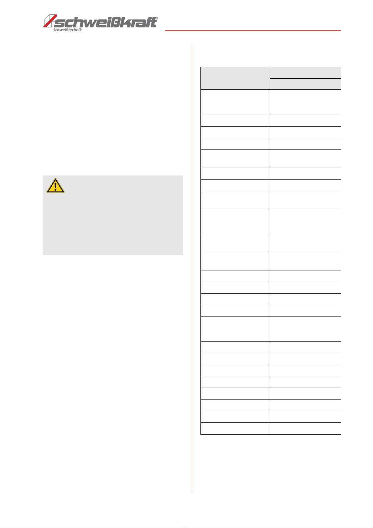
CAUTION!
This combination of symbol and signal words indi-
cates a potentially dangerous situation which may
lead to slight or minor injury if not avoided.
ATTENTION!
This combination of symbol and signal words indi-
cates a possibly dangerous situation which may lead
to property and environmental damages if they are
not avoided.
NOTE!
This combination of symbol and signal words indi-
cates a potentially dangerous situation which may
lead to material or environmental damage if not
avoided.
Tips and recommendations
This symbol highlights useful tips and recommenda-
tions as well as information for an efficient and trou-
ble-free operation.
ATTENTION!
Serious injury can occur if the user ignores the war-
nings and/or refuses to follow the instructions in the
operating manual!
ATTENTION!
Before use make sure the protection films on both
inside & outside protection lens are removed (if availa-
ble).
CAUTION!
If corrective goggles are worn under the welding helmet
under the welding helmet, the following must be obser-
ved:
Impacts on the welding helmet pose a potential risk of
injury for people wearing standard corrective goggles.