Setcom IM-950 User manual

IM-950
INSTALLATION AND USERS GUIDE
3019 Alvin DeVane Blvd.
Ste. 560
Austin, TX 78741
Phone: (650) 965-8020
CORPORATION
®
TECH SUPPORT: 650-965-8020 ext. 703
The IM-950 is a Radio Interface and full-duplex Intercom with
the following features:
· Single Radio Interface, Fully Adjustable RX/TX levels,
use with RC or RCB cable types
· 4 Radio Transmit Circuits, TRS Headset Jacks
(extension TX station ES-900-xx (xx denotes cable length)
is available)
· Remotes Port for Up to 4 Intercom-Only Positions
· 2 PTT Footswitch or Pushbutton Station Ports:
A: assignable to HS1 or HS2
B: assignable to HS3 or HS4
(Footswitch is FS-950, Pushbutton is PBS-950)
· AUX Audio Input (requires 25-0088-ISO cable)
(see notes on page 3)
· Automatic AUX Muting on PTT or Radio RX,
3-second delayed recovery from AUX Mute
(either PTT or RX mute function can be turned off)
· Fully Isolated DC Power for Noise Immunity, operates
on 12 to 24 Volts DC
· TX Audio PTT Lockout, only 1 user can transmit at any
time, and only that users’ voice is sent to radio
· Can connect to 2 radios with RRC-950
(requires 25-0108 cable)
Questions or technical issues? Please call:
IM-950_UserGuide_REV_D Page of1 13
AUX
AUDIO
HEADSET 1 HEADSET 2 HEADSET 3 HEADSET 4
RADIO REMOTES
POWER
A
FOOTSWITCH
B
RRC
464.100
TAC 1
Radio Cable part number is determined by radio
manufacturer, model number, and length of cable.
See https://setcomcorp.com/cr/radio.php for more info
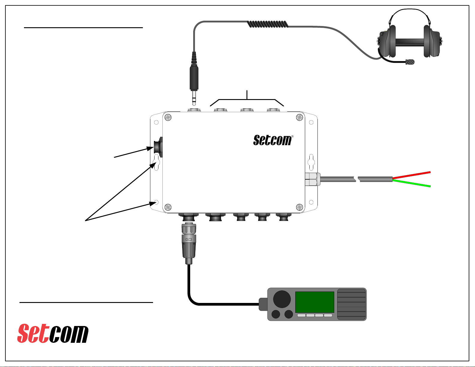
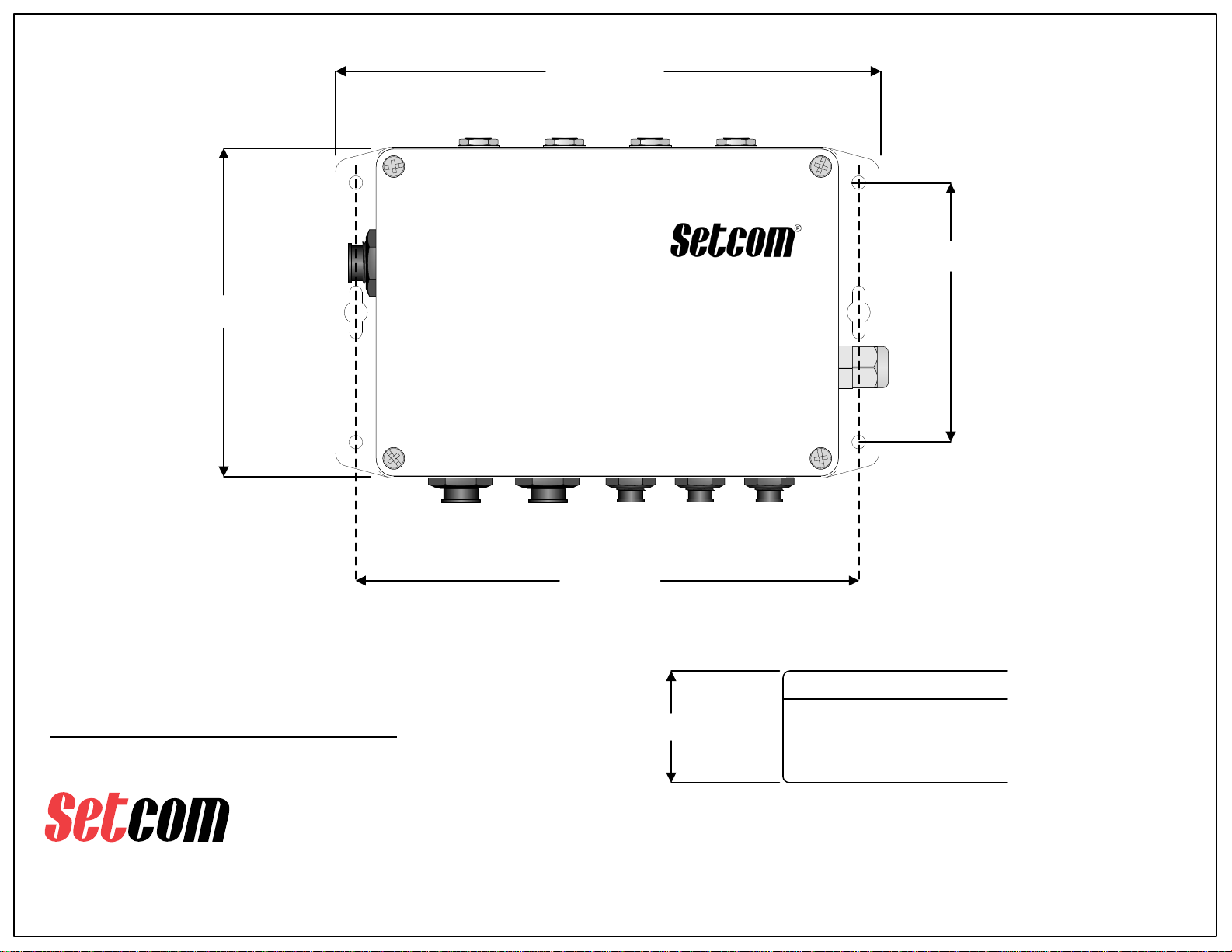
Mount the IM-950 using the 4 small
mounting holes or the 2 larger holes
on the enclosure flanges.
Mounting screws are supplied by user.
See pg.13 for Basic Dimensions
IM-950 Typical Installation
Radio, Headsets, and Power
3019 Alvin DeVane Blvd.
Ste. 560
Austin, TX 78741
Phone: (650) 965-8020
CORPORATION
®
TECH SUPPORT: 650-965-8020 ext. 703
Questions or technical issues? Please call: RC or RCB
Radio Cable
AUX
AUDIO
HEADSET 1 HEADSET 2 HEADSET 3 HEADSET 4
RADIO REMOTES
POWER
A
FOOTSWITCH
B
RRC
If 2 radios are required, a
Setcom RRC-950 can be
connected to the RRC Jack.
Refer to the RRC-950 User
Guide for more information.
Mobile Radio
CSB-900x or
other TX
Headset with
TRS plug
TX Headsets can be plugged into any of the
headset jacks. A 900W4-BASE (wireless
base station), or an ES-900-xx Remote
Transmit Station, can also be plugged in to
any of the headset jacks.
DC Power Cable RED = +V
GREEN = GROUND
Connect the DC Power cable to a 12 to
24 VDC power connection.
The IM-950 has an internal 1A ATO
fuse, but it is recommended to connect
the unit to a fused power source.
Refer to the 900W4-BASE instructions for
more information on that product, such as
required cables and general installation notes.
Page of2 13
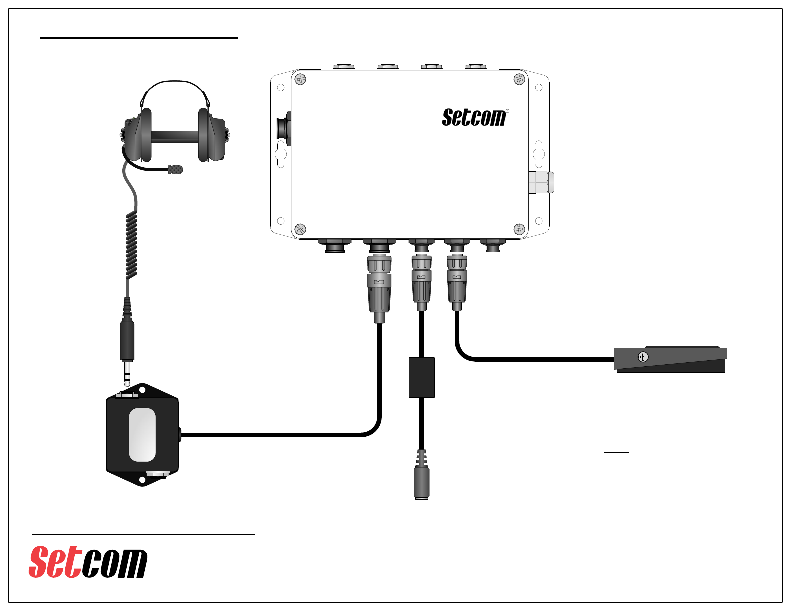
IM-950 Typical Installation
Remotes, Aux Audio, and PTT
Footswitches
3019 Alvin DeVane Blvd.
Ste. 560
Austin, TX 78741
Phone: (650) 965-8020
CORPORATION
®
TECH SUPPORT: 650-965-8020 ext. 703
Questions or technical issues? Please call:
AUX
AUDIO
HEADSET 1 HEADSET 2 HEADSET 3 HEADSET 4
RADIO REMOTES
POWER
A
FOOTSWITCH
B
RRC
FS-950 PTT Footswitch
PBS-950 PTT Pushbutton
switch options are available
Setcom
JS-900-xx
SN:S000011111
CSB-901x or
other Intercom
Headset with
TRS plug
JS-900-xx
For two Intercom Headset
positions, a JS-900-xx is used
(xx denotes cable length), if more
Intercom Headsets are required, a
JS-900-xx unit can be connected
through a JS-901-xx unit to allow
up to 4 Intercom Headsets.
25-0088-ISO
Cable
An Auxiliary Audio source such as an MP3 player or
a portable CD player can be connected to the IM-
950 through use of the 25-0088-ISO Cable and a
3.5mm male-to-male patch cable (user supplied).
Volume is controlled by the Audio source.
Footswitch input A can control either
HEADSET 1 or HEADSET 2, and input B can
control either HEADSET 3 or HEADSET 4.
(factory defaults are input A set to Headset 1
and input B set to HEADSET 3).
1 or 2 Footswitches or
Pushbutton PTT stations can
be connected to the IM-950.
Page of3 13
NOTE:
The AUX AUDIO input is not intended for
use as an additional radio receive input, it
will not support BTL-type (Balanced)
speaker outputs from radios.
It will support mono or stereo Single-
Ended line level audio such as that from
an audio device headphone output, or
certain types of radios with Single-Ended
audio out such as a scanner.
If there are questions, consult Setcom
Tech Support.

NCS12S1212C
OFF
IM-950 Adjustments
RX Audio, Muting Control
RX LEVEL
VR1
RX RANGE
SW4
RX RANGE
SW4
(shown enlarged)
ONOFF
N O
1 2
· To increase RX Level,
set S1 to ON
· To decrease RX level,
set S2 to ON
· Do not set both sections
to ON, use only one
section or the other
RX Audio level is normally set by the volume control on the mobile radio.
If further adjustment is needed, RX LEVEL control VR1 can be used to adjust RX volume.
If more adjustment range is needed, the RX RANGE switch SW4 can be set to allow
higher or lower level settings.
3019 Alvin DeVane Blvd.
Ste. 560
Austin, TX 78741
Phone: (650) 965-8020
CORPORATION
TECH SUPPORT: 650-965-8020 ext. 703
Questions or technical issues? Please call:
MUTING
CONTROL
SW2
MUTING CONTROL
SW2
(shown enlarged)
ONOFF
N O
1 2
Normally, muting control is factory preset to
mute Aux Audio when either a PTT button is
pressed, or when RX audio from a radio is
detected.
· To turn off RX muting set S1 to OFF
· To turn off PTT muting set S2 to OFF
S1
S2
S1
S2
Page of4 13
Loosen top cover screws and carefully
remove cover to make adjustments

NCS12S1212C
OFF
IM-950 Adjustments
TX Level, PTT Footswitch Control
3019 Alvin DeVane Blvd.
Ste. 560
Austin, TX 78741
Phone: (650) 965-8020
CORPORATION
TECH SUPPORT: 650-965-8020 ext. 703
Questions or technical issues? Please call:
For Factory Calibration
DO NOT ADJUST
TX LEVEL
SW5
TX Audio level is normally factory-preset to the
correct level for the radio type specified when the
IM-950 is ordered.
If a different TX level is required, the TX LEVEL
SW5 can be set from 0 (highest) to F (lowest) to
accommdate various radios.
Call Setcom Tech Support for assistance if needed.
PTT FOOTSWITCH SELECT
SW1
FOOTSWITCH SELECT
SW1
(shown enlarged)
Page of5 13
SB
HS2
HS1
HS4
HS3
PTT Footswitch assignment can be set using
SW1. The factory default is to assign input A
to HEADSET 1 and input B to HEADSET 3.
These settings can be changed as follows:
· Input A can be changed to HEADSET 2
by setting SA to HS2
· Input B can be changed to HEADSET 4
by setting SB to HS4
SA
Input
AInput
B
HS1 HS2 HS3 HS4
Loosen top cover screws and carefully
remove cover to make adjustments
3019 Alvin DeVane Blvd.
Ste. 560
Austin, TX 78741
Phone: (650) 965-8020
CORPORATION
®
TECH SUPPORT: 650-965-8020 ext. 703
Questions or technical issues? Please call:
Page of6 13
AUX
AUDIO
HEADSET 1 HEADSET 2 HEADSET 3 HEADSET 4
RADIO REMOTES
POWER
A
FOOTSWITCH
B
RRC
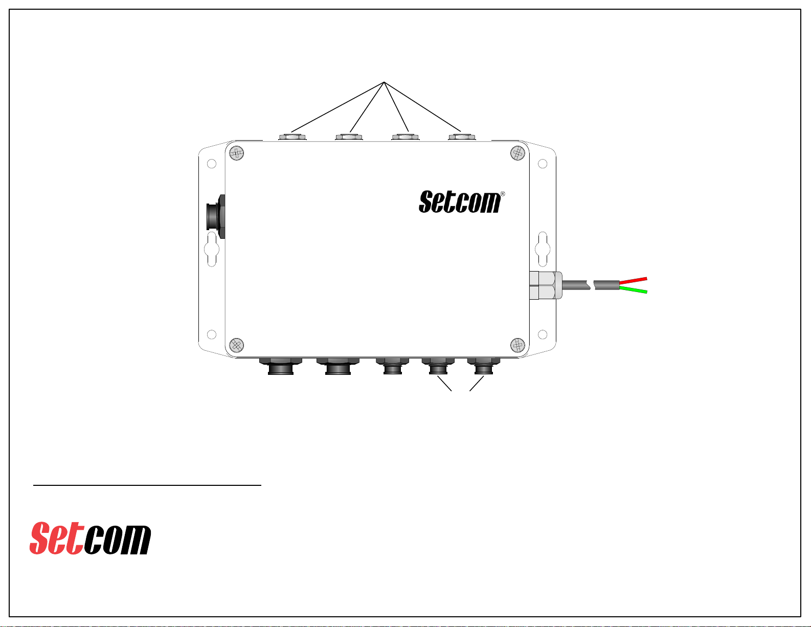
1 2 3 4
5
6
7
DC Power Cable
IM-950
The following pages have detailed
Connector Pinout Information
3019 Alvin DeVane Blvd.
Ste. 560
Austin, TX 78741
Phone: (650) 965-8020
CORPORATION
®
TECH SUPPORT: 650-965-8020 ext. 703
Questions or technical issues? Please call:
Page of7 13
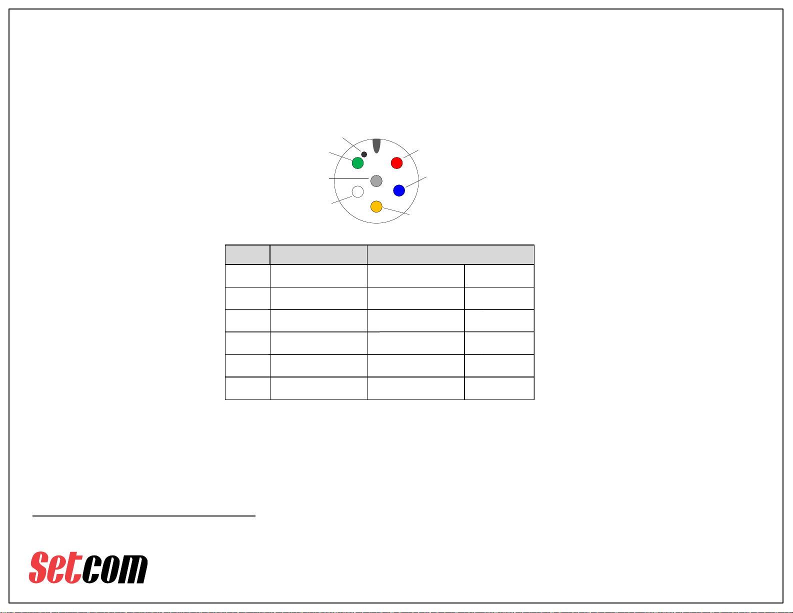
· 1. RADIO –
Works with any Setcom RC or RCB Radio cable –see https://setcomcorp.com/cr/radio.php
Mating Connector is Conxall PN 6282-6SG-519 (Setcom PN 11-7032) Mini-Con-X 6-position Cable End
PTT
Spkr High
Spkr Low
Mic Low
Mic High
Ground
1
2
3
4
5
6
Pin No.
1
2
3
4
Front view
Ground
Spkr Low
Mic Low
PTT
Spkr High
5
6
Mic High
Dot indicating Pin 1
Active Low
Speaker +
Power Ground
Audio Ground
Speaker -
Output
Input
Output
Input
Level - *
Radio Specific
Reference
Reference
Pin Name Pin Function
* Default Level = 80mVrms output when TX LEVEL Setting is set to “5”
with a 80mVrms input from a headset jack input (1 -4)
Note: The Mic Output pins on the Radio port and the RRC port are "gated".
TX audio will only appear on these pins when PTT is active.

3019 Alvin DeVane Blvd.
Ste. 560
Austin, TX 78741
Phone: (650) 965-8020
CORPORATION
®
TECH SUPPORT: 650-965-8020 ext. 703
Questions or technical issues? Please call:
Page of8 13
Mic Bias
Speaker
Mic
Ground
1
2
3
4
+8Vdc
Ground
Radio Receive/
Intercom audio
Input
Bias V
output
Reference
· 2. REMOTES –
Up to 4 Intercom-Only Positions
1
23
Front view
Speaker
Ground
MIC Bias
(+8Vdc)
4
Mic
Dot indicating Pin 1
Pin No. Pin Name Pin Function
Intercom audio

3019 Alvin DeVane Blvd.
Ste. 560
Austin, TX 78741
Phone: (650) 965-8020
CORPORATION
®
TECH SUPPORT: 650-965-8020 ext. 703
Questions or technical issues? Please call:
Page of9 13
· 3. AUX AUDIO - (requires 25-0088-ISO cable) An Auxiliary Audio source such as an MP3
player or a portable CD player can be connected to the IM-950 through use of the 25-0088-ISO Cable
and a 3.5mm male-to-male patch cable (user supplied). Volume is controlled by the Audio source.
Note: the 25-0088-ISO is Transformer Isolated, this is to help eliminate possible ground loop noise.
12
3
Front view
Ground
Speaker R
Speaker L
Speaker L
Ground
1
2
3
Input
Reference
Speaker R Input
NOTE:
The AUX AUDIO input is not intended for use as an additional radio receive input, it will not support
BTL-type (Balanced) speaker outputs from radios.
It will support mono or stereo Single-Ended line level audio such as that from an audio device
headphone output, or certain types of radios with Single-Ended audio out such as a scanner.
Stereo input signal is summed to mono, as the system and headsets do not support stereo audio.
Pin No. Pin Name Pin Function
line level audio
line level audio
Ground

3019 Alvin DeVane Blvd.
Ste. 560
Austin, TX 78741
Phone: (650) 965-8020
CORPORATION
®
TECH SUPPORT: 650-965-8020 ext. 703
Questions or technical issues? Please call:
Page of10 13
· 4. Footswitch A/B -
2 PTT Footswitch or Pushbutton Station Ports:
A: Assignable to HS1 or HS2
B: Assignable to HS3 or HS4
(Footswitch is FS-950, Pushbutton is PBS-950)
(factory defaults are input A set to Headset 1 and input B set to HEADSET 3).
Pin No. Pin Name Pin Function
PTT_DET
Ground
1
2Ground
Input
Reference
Signal
· 5. Power -
DC Power Cable RED = +V
GREEN = GROUND
Connect the DC Power cable to a 12 to 24 VDC power connection.
The IM-950 has an internal 1A ATO fuse, however it is recommended to connect the unit to a
fused power source.
12
Front view
GroundPTT_DET

3019 Alvin DeVane Blvd.
Ste. 560
Austin, TX 78741
Phone: (650) 965-8020
CORPORATION
®
TECH SUPPORT: 650-965-8020 ext. 703
Questions or technical issues? Please call:
Page of11 13
· 6. Headset 1 - 4 (IM-950)
Any System 900 Radio Transmit (RT) Headset can be plugged into any of the IM-950 headset jacks 1 - 4.
1kΩ
Ring
Tip
Sleeve
+
47uF
270Ω
R3
C2
MIC
Speaker
Ground
Sample Wiring of a 900 RT headset
Tip
Ring
Sleeve
0.25" Panel Jack
Tip, Ring, Sleeve (TRS), PC Mnt
3019 Alvin DeVane Blvd.
Ste. 560
Austin, TX 78741
Phone: (650) 965-8020
CORPORATION
®
TECH SUPPORT: 650-965-8020 ext. 703
Questions or technical issues? Please call:
Page of12 13
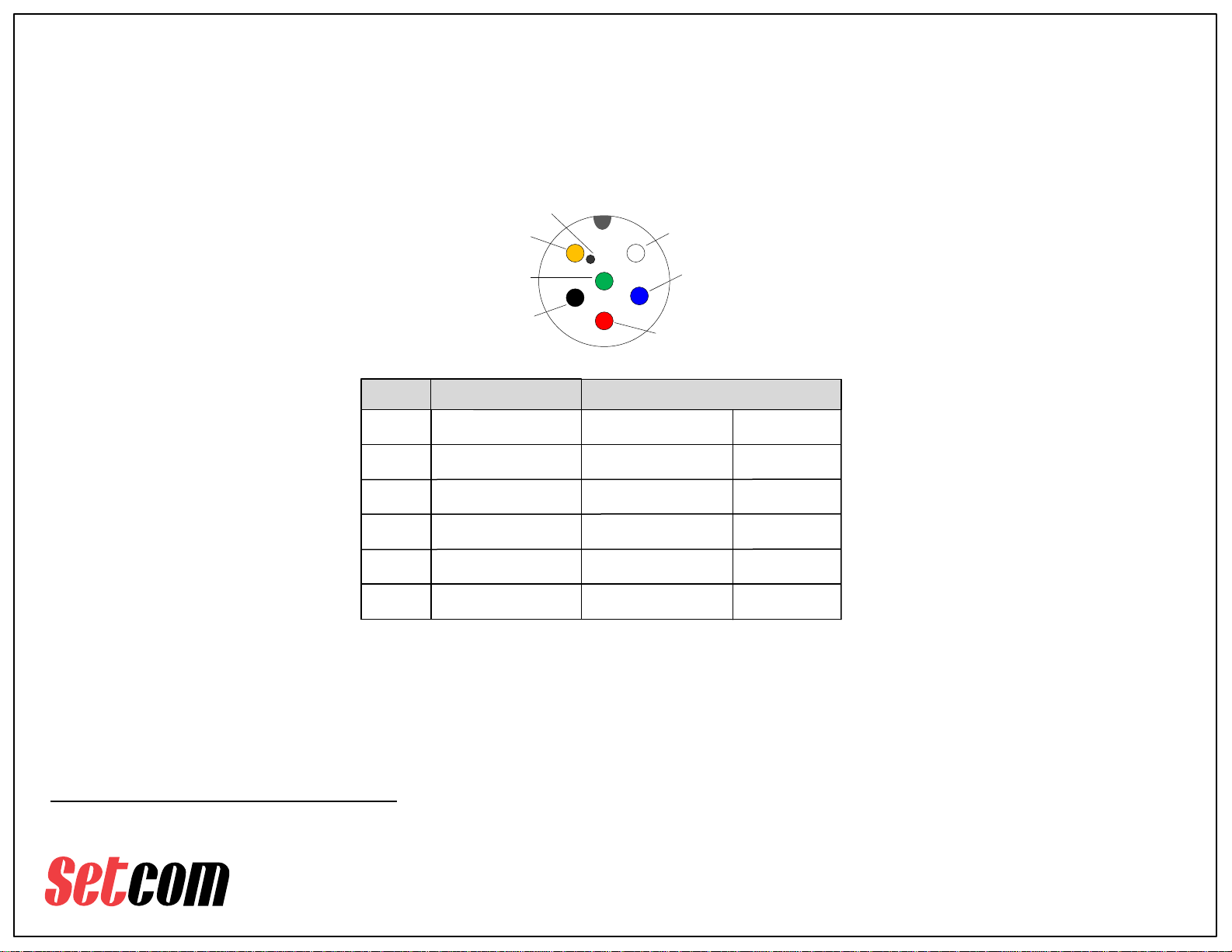
· 7. RRC (Radio Routing Controller) –
Switches host between 2 radios, Speaker Audio switching is selectable: Summed or Switched. Individual
Speaker Audio Level control. Individual TX Audio level control. Does not require external power. Uses 25-
0108 RRC Cable to connect to host. Accepts RC or RCB Radio Cables. Set IM-950 TX out at switch position 7
· Mating Connector is Conxall PN 6282-6SG-519 (Setcom PN 11-7032) Mini-Con-X 6-position Cable End
PTT
RX Audio
Mic Low
Mic +
1
2
3
4
5
6
Pin No.
1
2
3
4
Front view
PTT
MIC+
Mic Low
V+
Ground
5
6
RX Audio
Dot indicating Pin 1
Active Low
Power Ground
Audio Ground
Receive audio
Output
Output
Input
Level - *
Radio Specific
Reference
Reference
Pin Name Pin Function
* Default Level = 70mVrms output when TX LEVEL Setting is set to “7”
with a 80mVrms input from a headset jack input (1 -4)
V+
Output
Ground
+12Vdc
Note: The Mic Output pins on the Radio port and the RRC port are "gated".
TX audio will only appear on these pins when PTT is active.
3019 Alvin DeVane Blvd.
Ste. 560
Austin, TX 78741
Phone: (650) 965-8020
CORPORATION
®
TECH SUPPORT: 650-965-8020 ext. 703
Questions or technical issues? Please call:
Page of13 13
AUX
AUDIO
HEADSET 1 HEADSET 2 HEADSET 3 HEADSET 4
RADIO REMOTES
POWER
A
FOOTSWITCH
B
RRC
7.91 Inches
4.82 Inches
7.32 Inches
3.78 Inches
C
L
2.17 Inches
IM-950
Basic Dimensions
Table of contents
Other Setcom Recording Equipment manuals


