1. Safety
Before using the inverter, please read all instructions and cautionary markings on the unit and manual.
Put the instructions where you can take them easily.
The inverter of us strictly conforms to related safety rules in design and test. Local safety regulations
shall be followed during installation, operation and maintenance. Incorrect operation work may cause
injury or death and damage to the inverter and other operator or a third party.
To avoid injury and damage to the inverter and other operator,please follow the safety precautions.
7
6
Safety Safety
1.2 Safety Instruction
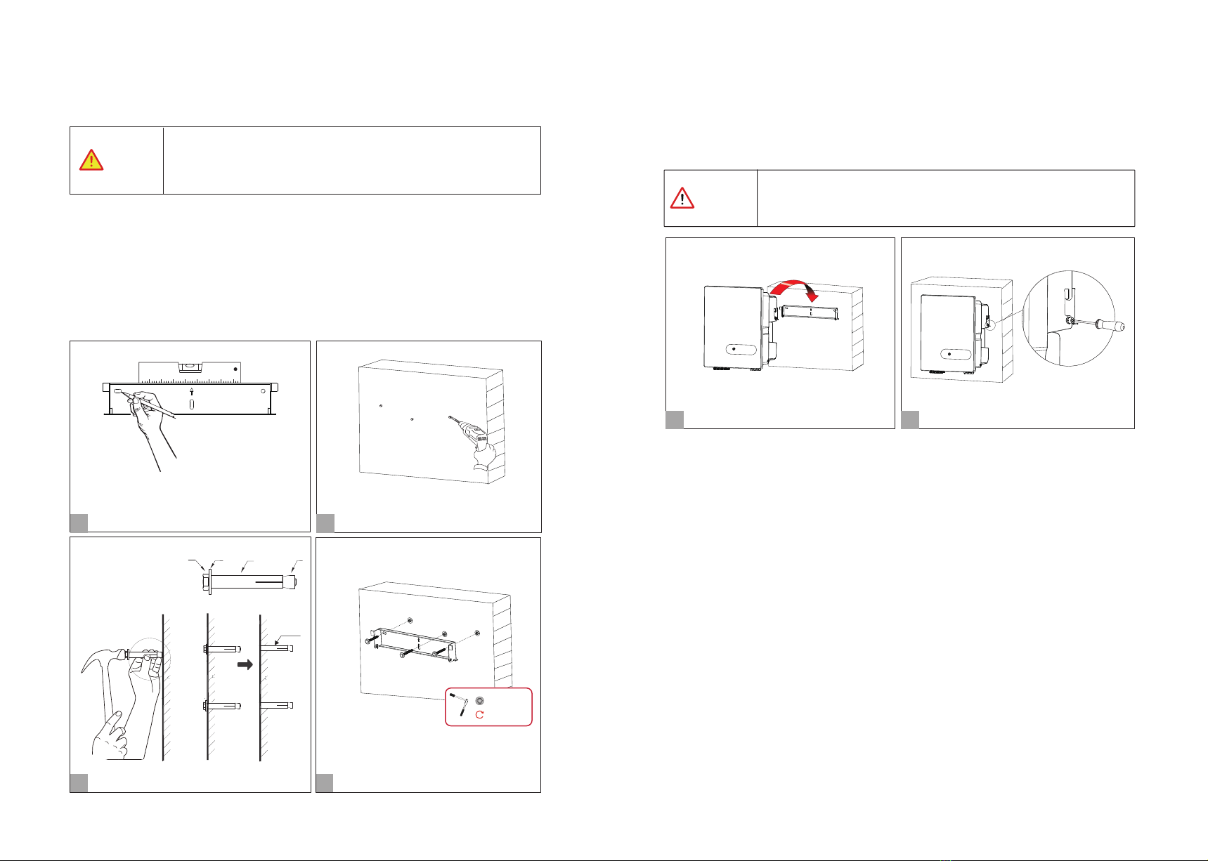
Installation and maintenance of inverters must be performed by qualified personnel, in accordance with
local electrical standards, wiring regulations and requirements of local power authorities.
The temperature of some parts of the inverter may exceed 60℃ during operation, do not touch the
inverter during operation to avoid being burnt.
Ensure children are kept away from inverters.
Take appropriate measures to avoid electric shock.
Don’t open the front cover of the inverter. Apart from performing work at the wiring terminal,
touching or changing components without authorization may cause injury to people, damage to
inverters and annulment of the warranty.
Ensure the output voltage of the proposed PV array is lower than the maximum rated input voltage of
the inverter; otherwise the inverter may be damaged and the warranty annulled.
When exposed to sunlight, the PV array generates dangerous high DC voltage. Please operate according
to our instructions, or it will result in danger to life.
Don’t insert or pull the terminals when the inverter is running.
After the inverter is powered off, the remaining electricity and heat may still cause electric shock and
body burns. Do not touch parts of inverter for 10 minutes after disconnection from the power sources.
Danger of high voltage!
Only qualified personnel may perform work on the inverter.
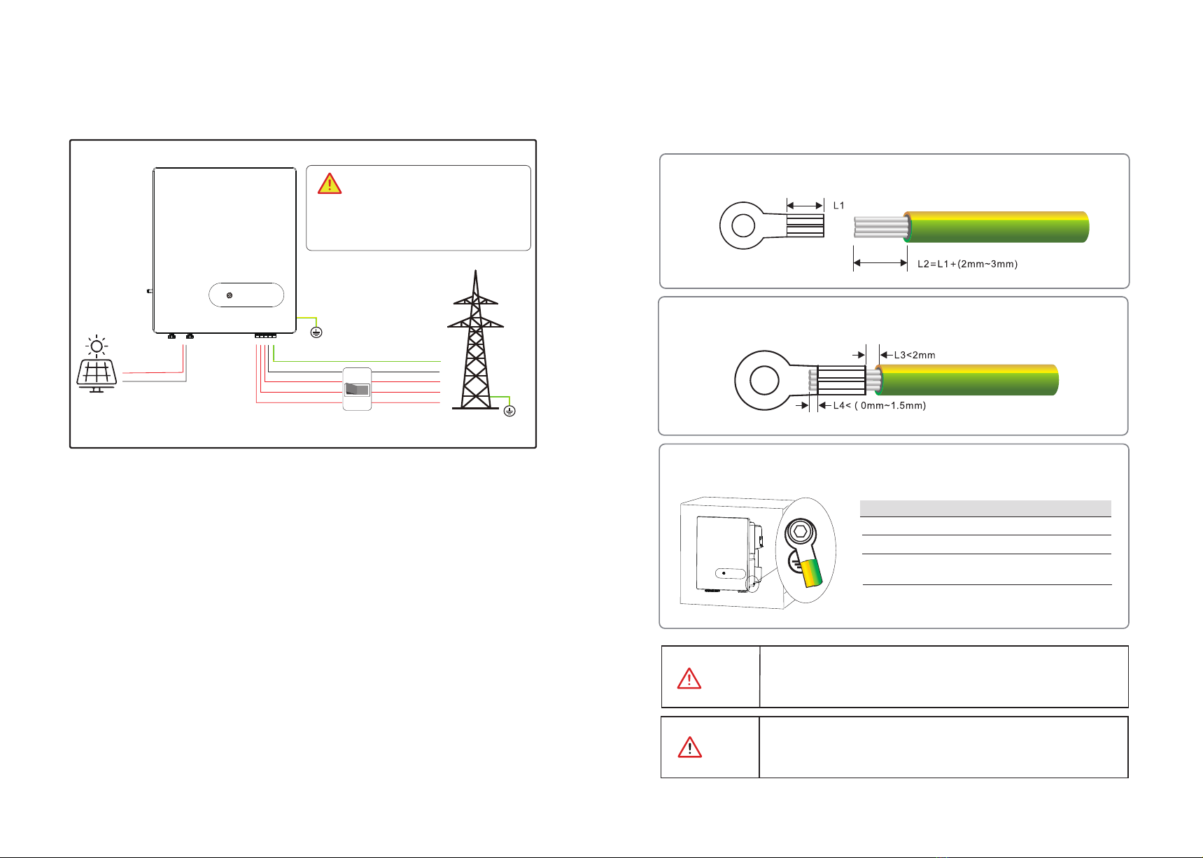
Grounding terminal
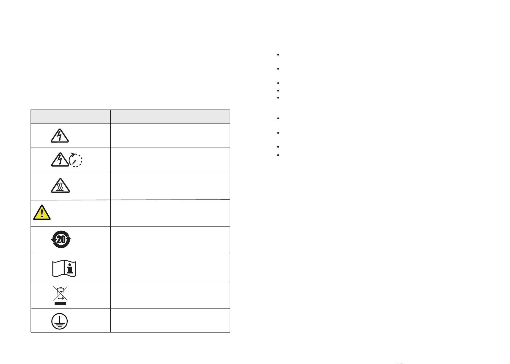
1.1 Symbols Used
Safety Symbol Description
Residual voltage exists after the inverter is powered off. It
takes 5 minutes for system to discharge to a safe voltage.
Danger of hot surface
Don’t dispose of the inverter with the household waste.
Do not disconnect under load!
5 mins
Environmental Protection Use Period
Refer to the operating instructions
The sign of caution stick on inverter.
Do not disconnect with load, otherwise there will be
danger of fire.