Rockwell Automation 2361-SPM04A User manual

User
Manual
Bulletin 1395
Digital DC Drive
in Bulletin 2361
Motor Control Centers for
Drive Systems
1250, 1650, 3000A DC
Series C

Important User Information Solid-State equipment has operational characteristics differing from
those of electromechanical equipment. “Safety Guidelines for the
Application, Installation and Maintenance of Solid-State Controls”
(Publication SGI-1.1) describes some important differences between
solid-state equipment and hard-wired electromechanical devices.
Because of this difference, and also because of the wide variety of
uses for solid-state equipment, all persons responsible for applying
this equipment must satisfy themselves that each intended application
of this equipment is acceptable.
In no event will Rockwell Automation be responsible or liable for
indirect or consequential damages resulting from the use of
application of this equipment.
The examples and diagrams in this manual are included solely for
illustrative purposes. Because of the many variables and requirements
associated with any particular installation, the Rockwell Automation
cannot assume responsibility or liability for actual use based on the
examples and diagrams.
No patent liability is assumed by Rockwell Automation with respect
use of information, circuits, equipment, or software described in this
manual.
Reproduction of the contents of this manual, in whole or in part,
without written permission of Rockwell Automation is prohibited.
Throughout this manual we use notes to make you aware of safety
considerations:
Attention statements help you to:
• identify a hazard
• avoid a hazard
• recognize the consequences
Datab is a trademark of W. H. Brady Company
CENTERLINE, PLC-5, DriveTools, and ControlNet are trademarks of Rockwell International or its
subsidiaries.
!ATTENTION: Identifies information about practices
or circumstances that can lead to personal injury or
death, property damage or economic loss.

Table of Contents
Publication 2361-5.01 July 1998
Preface Contents . . . . . . . . . . . . . . . . . . . . . . . . . . . . . . . . . . . . . . . . . . P-1
Who Should Use This Manual . . . . . . . . . . . . . . . . . . . . . . . . . . . P-1
Purpose of This Manual . . . . . . . . . . . . . . . . . . . . . . . . . . . . . . . P-1
Safety Precautions . . . . . . . . . . . . . . . . . . . . . . . . . . . . . . . . . . . P-2
Contents of this Manual . . . . . . . . . . . . . . . . . . . . . . . . . . . . . . . P-3
Related Documentation . . . . . . . . . . . . . . . . . . . . . . . . . . . . . . . P-4
Style of this Manual . . . . . . . . . . . . . . . . . . . . . . . . . . . . . . . . . . P-5
Terms and Abbreviations . . . . . . . . . . . . . . . . . . . . . . . . . . . . . . P-5
Receiving Your Drive System . . . . . . . . . . . . . . . . . . . . . . . . . . . P-5
Rockwell Automation Support . . . . . . . . . . . . . . . . . . . . . . . . . . . P-6
Local Product Support . . . . . . . . . . . . . . . . . . . . . . . . . . . . . . P-6
Technical Product Assistance . . . . . . . . . . . . . . . . . . . . . . . . . P-6
Chapter 1 Product Overview
Contents . . . . . . . . . . . . . . . . . . . . . . . . . . . . . . . . . . . . . . . . . . 1-1
Standard Features . . . . . . . . . . . . . . . . . . . . . . . . . . . . . . . . . . . 1-1
Standard Options . . . . . . . . . . . . . . . . . . . . . . . . . . . . . . . . . . . . 1-2
Hardware Overview . . . . . . . . . . . . . . . . . . . . . . . . . . . . . . . . . . 1-3
Control Boards . . . . . . . . . . . . . . . . . . . . . . . . . . . . . . . . . . . . . . 1-4
Main Control Board . . . . . . . . . . . . . . . . . . . . . . . . . . . . . . . . . 1-5
Door-Mounted Programming Terminal . . . . . . . . . . . . . . . . . . 1-6
Adapter Boards . . . . . . . . . . . . . . . . . . . . . . . . . . . . . . . . . . . 1-6
Control/Power Interface Boards . . . . . . . . . . . . . . . . . . . . . . . . . 1-7
Power Stage Interface Board . . . . . . . . . . . . . . . . . . . . . . . . . 1-8
Unit Power Supply Board . . . . . . . . . . . . . . . . . . . . . . . . . . . . 1-9
Feedback Board . . . . . . . . . . . . . . . . . . . . . . . . . . . . . . . . . . 1-10
24V DC Power Supply . . . . . . . . . . . . . . . . . . . . . . . . . . . . . . 1-10
Gate Interface Board . . . . . . . . . . . . . . . . . . . . . . . . . . . . . . . 1-11
Power Components . . . . . . . . . . . . . . . . . . . . . . . . . . . . . . . . . 1-12
Incoming Power Components . . . . . . . . . . . . . . . . . . . . . . . . 1-12
Incoming Devices . . . . . . . . . . . . . . . . . . . . . . . . . . . . . . . 1-12
AC Input Busbars . . . . . . . . . . . . . . . . . . . . . . . . . . . . . . . 1-12
Main Disconnect (Optional) . . . . . . . . . . . . . . . . . . . . . . . . 1-12
AC Line Fuses (Optional) . . . . . . . . . . . . . . . . . . . . . . . . . . 1-12
Control and Field Power . . . . . . . . . . . . . . . . . . . . . . . . . . 1-13
AC Line RC Suppressor (Optional) . . . . . . . . . . . . . . . . . . . 1-13

toc–ii Table of Contents
Publication 2361-5.01 July 1998
Armature Power Components . . . . . . . . . . . . . . . . . . . . . . . . 1-14
Armature Bridge . . . . . . . . . . . . . . . . . . . . . . . . . . . . . . . . 1-14
DC Contactor . . . . . . . . . . . . . . . . . . . . . . . . . . . . . . . . . . 1-16
Field Power Components . . . . . . . . . . . . . . . . . . . . . . . . . . . 1-17
Field Bridge . . . . . . . . . . . . . . . . . . . . . . . . . . . . . . . . . . . 1-18
Field-Pulse Transformer Board . . . . . . . . . . . . . . . . . . . . . 1-18
Chapter 2 Your 1250A DC Drive
Contents . . . . . . . . . . . . . . . . . . . . . . . . . . . . . . . . . . . . . . . . . . 2-1
Introduction . . . . . . . . . . . . . . . . . . . . . . . . . . . . . . . . . . . . . . . . 2-1
Drive Layout . . . . . . . . . . . . . . . . . . . . . . . . . . . . . . . . . . . . . . . . 2-2
Drive Schematics . . . . . . . . . . . . . . . . . . . . . . . . . . . . . . . . . . . . 2-3
Symbol Reference Chart . . . . . . . . . . . . . . . . . . . . . . . . . . . . . . . 2-6
Drive Structure . . . . . . . . . . . . . . . . . . . . . . . . . . . . . . . . . . . . . . 2-8
Conclusion . . . . . . . . . . . . . . . . . . . . . . . . . . . . . . . . . . . . . . . . . 2-8
Chapter 3 Your 1650A DC Drive
Contents . . . . . . . . . . . . . . . . . . . . . . . . . . . . . . . . . . . . . . . . . . 3-1
Introduction . . . . . . . . . . . . . . . . . . . . . . . . . . . . . . . . . . . . . . . . 3-1
Drive Layout . . . . . . . . . . . . . . . . . . . . . . . . . . . . . . . . . . . . . . . . 3-2
Drive Schematics . . . . . . . . . . . . . . . . . . . . . . . . . . . . . . . . . . . . 3-3
Symbol Reference Chart . . . . . . . . . . . . . . . . . . . . . . . . . . . . . . . 3-6
Drive Structure . . . . . . . . . . . . . . . . . . . . . . . . . . . . . . . . . . . . . . 3-8
Conclusion . . . . . . . . . . . . . . . . . . . . . . . . . . . . . . . . . . . . . . . . . 3-8
Chapter 4 Your 3000A DC Drive
Contents . . . . . . . . . . . . . . . . . . . . . . . . . . . . . . . . . . . . . . . . . . 4-1
Introduction . . . . . . . . . . . . . . . . . . . . . . . . . . . . . . . . . . . . . . . . 4-1
Drive Layout . . . . . . . . . . . . . . . . . . . . . . . . . . . . . . . . . . . . . . . . 4-2
Drive Schematics . . . . . . . . . . . . . . . . . . . . . . . . . . . . . . . . . . . . 4-3
Symbol Reference Chart . . . . . . . . . . . . . . . . . . . . . . . . . . . . . . . 4-6
Drive Structure . . . . . . . . . . . . . . . . . . . . . . . . . . . . . . . . . . . . . . 4-8
Conclusion . . . . . . . . . . . . . . . . . . . . . . . . . . . . . . . . . . . . . . . . . 4-8

Table of Contents toc–iii
Publication 2361-5.01 July 1998
Chapter 5 Installing Your Drive
Contents . . . . . . . . . . . . . . . . . . . . . . . . . . . . . . . . . . . . . . . . . . 5-1
Resources . . . . . . . . . . . . . . . . . . . . . . . . . . . . . . . . . . . . . . . . . 5-1
Physically Installing the Drive at Your Site . . . . . . . . . . . . . . . . . 5-2
Inspecting the Air Baffles . . . . . . . . . . . . . . . . . . . . . . . . . . . . 5-2
Preparing AC Input Entry . . . . . . . . . . . . . . . . . . . . . . . . . . . . . . 5-2
Installing and Configuring Your Drive . . . . . . . . . . . . . . . . . . . . . 5-4
Drive Disconnect . . . . . . . . . . . . . . . . . . . . . . . . . . . . . . . . . . 5-4
Wiring Recommendations . . . . . . . . . . . . . . . . . . . . . . . . . . . . 5-4
Drive Grounding . . . . . . . . . . . . . . . . . . . . . . . . . . . . . . . . . . . 5-5
Power Wiring . . . . . . . . . . . . . . . . . . . . . . . . . . . . . . . . . . . . . 5-5
Field Transformer . . . . . . . . . . . . . . . . . . . . . . . . . . . . . . . . . . 5-6
Installing the Field Transformer . . . . . . . . . . . . . . . . . . . . . . 5-7
Circuit Board Jumper Connections . . . . . . . . . . . . . . . . . . . . . 5-9
Armature Current Ratings . . . . . . . . . . . . . . . . . . . . . . . . . . . 5-12
Chapter 6 Starting Up Your Drive
Contents . . . . . . . . . . . . . . . . . . . . . . . . . . . . . . . . . . . . . . . . . . 6-1
Introduction . . . . . . . . . . . . . . . . . . . . . . . . . . . . . . . . . . . . . . . . 6-1
Voltage Measurements . . . . . . . . . . . . . . . . . . . . . . . . . . . . . . . . 6-1
Rated Armature and Field Currents . . . . . . . . . . . . . . . . . . . . . . . 6-2
Appendix A Drive Specifications
Contents . . . . . . . . . . . . . . . . . . . . . . . . . . . . . . . . . . . . . . . . . . A-1
General Specifications . . . . . . . . . . . . . . . . . . . . . . . . . . . . . . . . A-1
Unit Specifications . . . . . . . . . . . . . . . . . . . . . . . . . . . . . . . . . . . A-2
Electrical Specifications . . . . . . . . . . . . . . . . . . . . . . . . . . . . . . . A-3
Power Dissipation . . . . . . . . . . . . . . . . . . . . . . . . . . . . . . . . . . . A-4
Circuit Breaker Settings . . . . . . . . . . . . . . . . . . . . . . . . . . . . . . . A-5
Circuit Breaker Derating . . . . . . . . . . . . . . . . . . . . . . . . . . . . . . . A-6
Input Busbars . . . . . . . . . . . . . . . . . . . . . . . . . . . . . . . . . . . . . . . A-7
Air Baffle Layouts . . . . . . . . . . . . . . . . . . . . . . . . . . . . . . . . . . . . A-9

toc–iv Table of Contents
Publication 2361-5.01 July 1998
Appendix B Catalog Numbers and Spare Parts Kits
Contents . . . . . . . . . . . . . . . . . . . . . . . . . . . . . . . . . . . . . . . . . . B-1
Understanding Catalog Numbers . . . . . . . . . . . . . . . . . . . . . . . . B-1
Determining Catalog Numbers . . . . . . . . . . . . . . . . . . . . . . . . B-1
DC Drive Catalog Numbers . . . . . . . . . . . . . . . . . . . . . . . . . . . . . B-3
DC Drive Spare Parts Kits . . . . . . . . . . . . . . . . . . . . . . . . . . . . . . B-6
What Does a Spare Parts Kit Include? . . . . . . . . . . . . . . . . . . . B-6
Which Table Do I Use? . . . . . . . . . . . . . . . . . . . . . . . . . . . . . . B-6
Significance of Level Numbers . . . . . . . . . . . . . . . . . . . . . . . . B-6
Definition of Terms Used to Describe "Qty in Kit" . . . . . . . . . . B-7
Catalog Number Description . . . . . . . . . . . . . . . . . . . . . . . . . . B-7

Publication 2361-5.01 July 1998
Preface
Preface
Contents This preface will introduce you to the contents and purpose of this
manual. The following topics will be discussed in this preface:
Who Should Use This Manual This manualis intended for those who are responsible for installingor
operating a Rockwell Automation high-horsepower 1395 drive.
If you do not have a basic understanding of this unit, please refer to
the drive documentation, or contact your local Rockwell Automation
Drive Systems representative for more information before using this
product.
Purpose of This Manual This manual is a supplement to Publication 1395-5.40, titled 1395
Digital DC Drive–User Manual. This manual will cover:
• hardware overviews
• specifications
• installation instructions
• configuration and setup information
• spare parts
Topic Page
Who Should Use This Manual P-1
Purpose of This Manual P-1
Safety Precautions P-2
Contents of This Manual P-3
Related Documentation P-4
Style of This Manual P-5
Terms and Abbreviations P-5
Receiving Your Drive System P-5
Rockwell Automation Support P-6

Publication 2361-5.01 July 1998
P-2
Safety Precautions The following general precautions apply to Bulletin 2361 drive
system lineups:
!ATTENTION: Only those familiar with the drive
system, the products used in the system, and the
associated machinery should plan or implement the
installation, startup, and future maintenance of the
system. Failure to comply can result in personal injury
and/or equipment damage.
ATTENTION: Verify that all sources of AC and DC
power are deenergized and locked out or tagged out in
accordance with the requirements of ANSI/NFPA 70E,
Part II.
ATTENTION: The system may contain stored energy
devices. To avoid the hazard of electrical shock, verify
thatallvoltageoncapacitors hasbeendischargedbefore
attempting to service, repair, or remove a drive system
or its components. You should only attempt the
procedures in this manual if you are qualified to do so
and are familiar with solid-state control equipment and
the safety procedures in ANSI/NFPA 70E.
ATTENTION: An incorrectly applied or incorrectly
installed drive system can result in component damage
and/or a reduction in product life. Wiring or application
errors–such as undersizing the motor, incorrect or
inadequate AC supply, and excessive ambient
temperatures–can result in the malfunction of hte drive
equipment.
ATTENTION: This drive system contains parts and
assemblies that are sensitive to ESD (electrostatic
discharge). Staticcontrolprecautionsarerequiredwhen
installing, testing, or repairing this assembly.
ComponentdamagecanresultifESDcontrolprocedures
are not followed. If you are not familiar with static
control procedures, refer to Rockwell Automation
publication 8000-4.5.2, Guarding Against Electrostatic
Damage, or another adequate handbook on ESD
protection.

Publication 2361-5.01 July 1998
P-3
Contents of this Manual
Chapter Title Contents
Preface Purpose, background, and scope of this manual
1 Product Overview Theory of operation, features, and standard options
2 Your 1250A DC Drive Features, components, and schematics of the 1250A drive (R-frame)
3 Your 1650A DC Drive Features, components, and schematics of the 1650A drive (S-frame)
4 Your 3000A DC Drive Features, components, and schematics of the 3000A drive (T-frame)
5 Installing Your Drive Installation procedures and connection details
6 Starting Up Your Drive Information for starting up your drive
A Drive Specifications Electrical, environmental, and operational specifications
B Catalog Numbers and Spare Parts Kits Explanation of catalog numbers and listings of spare part kits

Publication 2361-5.01 July 1998
P-4
Related Documentation Several of the following documents will be needed to understand and
install your drive and its components. To obtain a copy of any
Rockwell Automation publication, please contact your local
Rockwell Automation office or distributor.
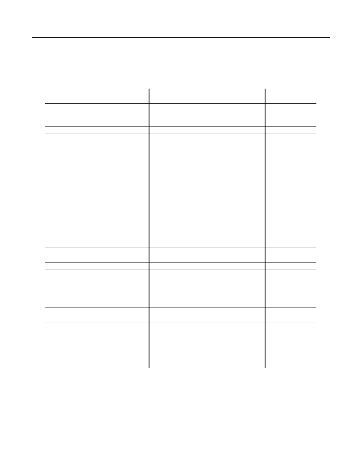
For Read This Document Document Number
Information on the 1395 digital DC drives Bulletin 1395 Digital DC Drive–User Manual 1395-5.40
Troubleshooting information for 1395 drives Bulletin 1395 Digital DC Drive–Troubleshooting
Manual
1395-5.45
Using the Bulletin 1300 programming terminal Bulletin 1300 Programming Terminal–User Manual 1300-5.5
PLC-5™ information PLC-5 Controllers Brochure 1785-1.2
Additional Information on joining and splicing
together MCCs
Joining and Splicing Vertical Sections–Instructions 2100-5.1
Details on receiving, handling, and storing
MCCs
Receiving, Handling, and Storing Motor Control
Centers–Instructions
2100-5.5
Provides procedures for those tasks that need
to be done at the customer’s site before system
start up
Bulletin 2300 Installation Manual 2300-5.1
Information and installation instructions for the
1395 Node Adapter Board
Bulletin 1395 Node Adapter Board–Installation and
Operation Manual
1395-5.9
Information and installation instructions for the
1395 Discrete Adapter Board
1395 Discrete Adapter Board–Installation and
Operation Manual
1395-5.12
Information and installation instructions for the
1395 ControlNet Communication Board
Bulletin 1395 ControlNet Communication Board–
User Manual
1395-5.37
Information and installation instructions for the
1395 Multi-Communication Board
Bulletin 1395 Multi-Communication
Board–Hardware/Software Reference Manual
1395-5.33
Information and installation instructions for the
1395 Digital Reference Adapter Board
Bulletin 1395 Digital Reference Adapter
Board–Hardware/Software Reference Manual
1395-5.55
A description of DriveTools™ software DriveTools Software Brochure 9303-1.0
Information on FD86N enclosures FD86N Drive Systems Enclosure Hardware–
Installation Manual
S-3062
Standards for electrical procedures (wiring
sizes, grounding, etc.)
National Electrical Code
(Published by the National Fire Protection
Association of Boston, MA)
ANSI / NFPA 70
An article on safety procedures Standard for Electrical Safety Requirements for
Employee Workplaces
ANSI / NFPA 70E
A complete listing of current documentation,
including ordering instructions. Also indicates
whether the documents are available on CD-
ROM or in multi-languages
Allen-Bradley Publication Index SD499
A glossary of industrial automation terms and
abbreviations
Industrial Automation Glossary AG-7.1

Publication 2361-5.01 July 1998
P-5
Style of this Manual The following conventions are used throughout this manual:
•‘ATTENTION’ statements, preceded with the symbol shown,
indicate a circumstance that could could lead to personal injury,
death, damage to property, or economic loss
•‘Important’ statements indicate key information for successfully
performing procedures and understanding the product
&
• Reference statements, preceded with the symbol shown, lead you
to other resources of information and instruction
• Horsepower ratings are provided at the start of each drive chapter
• Schematic and layout component abbreviations are explained in
component reference charts in each drive chapter
Terms and Abbreviations The following terms and abbreviations are used in this manual:
Receiving Your Drive System You, the Customer, are responsible for thoroughly inspecting the
equipment before accepting the shipment from the freight company.
Check the item(s) that you receive against your purchase order. If
any items are obviously damaged, do not accept the delivery until the
freight agent has noted the damage on the freight bill. Should you
discover any concealed damage during unpacking, you are
responsible for notifying the freight agent. In such a case, leave the
shipping container intact and request that the freight agent make a
visual inspection of the equipment.
!
Term Definition
armature rotating part of a motor
bridge assembly for power (AC/DC) conversion
busbar a large tin-plated copper conductor, used for high-power input and output
feedback status signals/voltages sent from components or external devices
gate an electrical switch
MCC motor control center, an enclosure for drive systems
MOV metal-oxide varistor, used for voltage spike protection
SCR silicon-controlled rectifier, used in power conversion
snubber a resistor/capacitor assembly, used for limiting excess voltage

Publication 2361-5.01 July 1998
P-6
Rockwell Automation Support Rockwell Automation offers support services worldwide, with Sales/
Support Offices, authorized distributors, and authorized Systems
Integrators located throughout the United States, plus Rockwell
Automation representatives in every major country in the world.
Local Product Support
Please contact your local Rockwell Automation representative for:
• sales and order support
• product technical training
• warranty support
• support service agreements
Technical Product Assistance
If you need to contact us for technical assistance, please review the
product and troubleshooting information in this manual first.
For the quickest possible response, please have the catalog numbers
of your products ready when you call.

Publication 2361-5.01 July 1998
Chapter
1
Product Overview
Contents The high-horsepower line of 1395 DC drives are Bulletin 1395
regulator products, with a high-horsepower silicon-controlled
rectifier (SCR) bridge, packaged in a Bulletin 2361 CENTERLINE™
motor control center, providing DC power for your high-horsepower
applications.
This first chapter will introduce you to the high-horsepower Bulletin
1395 drive covering these topics:
Standard Features The high-horsepower Bulletin 1395 drive includes the following
standard features:
• NEMA Class I construction
• High AIC instantaneous trip circuit breaker or line fuses for the
AC input, armature cell fuses, and a DC output contactor
• a six pulse, full-wave rectified armature converter
• 43A single-phase field regulator
• regenerative (1250, 1650, and 3000A) or non-regenerative (1250
and 1650A units only)
• 6:1 constant horsepower range
• digital control for current, velocity, and configuration
• auto tuning for velocity loop, current loop, field flux table
Topic Page
Standard Features 1-1
Standard Options 1-2
Hardware Overview 1-3
Control Components 1-4
Control/Power Interface Components 1-7
Power Components 1-12

Publication 2361-5.01 July 1998
1-2 Product Overview
• programmable functions (independent acceleration/deceleration
adjustment, preset speeds, current limit, tapered current limit,
tach loss recovery, system reset)
• protective features (instantaneous overcurrent, motor overload,
feedback loss, field loss, field economy, tach loss recovery,
system reset)
• CENTERLINE Bulletin 2361 Motor Control Center enclosure
Standard Options The following options are available for the high-horsepower 1395
drives:
• 115V AC discrete adapter board
• 24V DC discrete adapter board
• node adapter board
• multi-communications adapter board
• door-mounted DHT or EHT programming terminal
• ‘start/running’ and ‘clear fault/drive faulted’ door-mounted
illuminated pushbuttons
• ‘drive stop’, ‘hardwired stop’, ‘jog forward’, and ‘jog reverse’
door-mounted pushbuttons
• ‘power on’ door-mounted pilot light
• door-mounted speed potentiometer
• 1-2-3 speed selector
• blower starter (NEMA, IEC)
• 90A single-phase field regulator
• control circuit transformer
• top-hat input enclosure (standard for 3000A drive)
• line RC suppressor
• AC power thru bus
Note: Additional options are listed in Appendix B.

Publication 2361-5.01 July 1998
Product Overview 1-3
Hardware Overview The hardware components shown in form the high-horsepower 1395
DC drive. These drive components can be broken down into the
following three categories:
Figure 1.1
Drive Components
Hardware Description
Control Controls the drive system and interfaces with external devices
Control/Power Interface Interfaces the control components with the power components
Power Converts AC input to a DC supply for the motor
Unit
Power Supply
3-Phase
SCR Armature
Bridge
3-Phase AC Power
Feedback Board
Armature Current Feedback
AC Line Voltage Feedback
Motor
Armature
Field Current Feedback
Single-Phase
SCR Field
Bridge
TB7
F1 F2 F3 F4
M1
A1A2
Encoder
Armature DC Voltage Feedback
24V DC
Feedback
Power Supply
Power Stage
Interface Board
Main Control Board
TB3
Field PT &
Snubber
Programming
Terminal
DHT/DMT
J4 J1
J5
J2
J7 J6
J8
J9
J7
J1
J2
J6
J1
Encoder Feedback
Armature
Pulse
Transformer
Boards
J3A
-
J3D
J40
CONTROL CONTROL/POWER INTERFACE POWER
Circuit Breaker
TB8
Gate
Interface
Board
Field Transformer
(Only Used For AC Inputs of
575 and 660V AC)
Control
Transformer Fuses
MOVs
-+

Publication 2361-5.01 July 1998
1-4 Product Overview
Control Boards The control boards manage and control the system, processing status
information from system components and commanding drive
components and activities.
Figure 1.2
Control Boards
Feedback Board
Main Control
Board
CH1
FCT
F14 F15
Main Control Board
(behind adapter boards)
Feedback Board
Discrete or
Digital
Reference
Adapter Board
(Port A )
MP
24V DC Supply
Main Control Board Adapter Boards
O
PTIONAL
Communication
Adapter Board
(Port B)
O
PTIONAL

Publication 2361-5.01 July 1998
Product Overview 1-5
Main Control Board
The main control board is the center of the control processing. This
board has a number of test points and jumpers that are used during
startup and troubleshooting. Refer to the troubleshooting manual for
more information on test points and jumpers.
Figure 1.3
Main Control Board
J7 J6
Port A
(To Adapter Board)
Port B
(To Adapter Board)
VP
CP
SP
J14
1
2
3
Connection
To
Encoder
J10
1 2 3
Connection to Power
Stage Interface Board
Connection to Power
Stage Interface Board
Connection to
Programming Terminal
J2 J4 J5
TP2 TP5
J9
1 2 3
J8
1 2 3
TP9 TP6
TP12
TP15
TP13
TP11
TP23
TP32
TP35
TP24
TP25
TP42
TP50
TP45
TP46
TP21
TP33 TP34
TP27 TP26
TP31 TP29
TP28
TP19
TP10
TP30TP38
TP8 TP39TP17
TP43
TP1
TP41
TP20
TP47
TP20
TP44
TP49
TP58
TP55
+12V
TP57
AGND
TP52
DGND
TP56
-12V
TP51
+5V
TP58
ISO +5V
TP53
IGND
TP54
ISO+12V

Publication 2361-5.01 July 1998
1-6 Product Overview
Door-Mounted Programming Terminal
The door-mounted Bulletin 1300 programming terminal is the
interface module used to program and control the drive (typically
used in standalone applications). This terminal has an LCD screen
and a 24-key environment-safe keypad.
Adapter Boards
Optional adapter boards (such as the discrete adapter board, digital
reference adapter board, node adapter board, and multi-
communication adapter board) connect the drive to networks and
provide I/O capabilities.
&
Adapter board and programming terminal publications are listed in
the preface of this manual. Please refer to the appropriate manuals for
more information.

Publication 2361-5.01 July 1998
Product Overview 1-7
Control/Power Interface Boards Control/power interface boards are used to provide a link between
control boards (which are responsible for managing the drive), and
power components (which are closely associated with the actual drive
hardware and operations).
The following items are used to provide this interfacing:
• power stage interface board
• unit power supply board
• feedback board
These items are located on the control module in the disconnect bay
of the drive, and are arranged as shown below. Accessibility to the
power stage interface board and the unit power supply is gained by
lowering the front panel.
Figure 1.4
Control/Power Interface Boards
Unit Power Supply
Board
Power Stage
Interface Board
J9
TB1
F20
F21
12345 789
10
F14 F16
FAN 4
2MOV
3MOV
43A Field
Bridge
FCT
CH1
Field Pulse Transformer
and Snubber Board
24V DC Supply
MP
F4
F15
FAN 4
2MOV
3MOV
Option 14FX
Field Bridge
FCT
CH1
Gate Interface
Board
Alternate Field Bridge
Configuration
Feedback Board

Publication 2361-5.01 July 1998
1-8 Product Overview
Power Stage Interface Board
The power stage interface board is used as the chief interface between
the main control board and other boards of the system. This board is
responsible for distributing power and control signals to and from the
main control board, gate interface board, field-pulse transformer
board, feedback board, and unit power supply. Refer to Figure 1.1 to
see how this board is connected in the drive.
Figure 1.5
Power Stage Interface Board
&
The test points and jumpers shown in the diagram are used for startup
and troubleshooting procedures. Refer to the troubleshooting manual
for more information on test points and jumpers.
J3D
J2J6
J7
J1
J10
J8 J9
Connection to Main Control Board Connection to Main Control Board
Connections to
Gate Interface Board
Connection to
Feedback Board
Connection to
Field Transformer
Connection to
Unit Pow er Supply
J3C J3B J3A
TB1
TP8
(-12V)
TP7
(Gnd)
TP6
(+12V)
TP5
(+5V)
TP9
TP1
(+24V)
TP3
TP2
J12
J11
Connection to
Main Contactor, Pilot Relay,
and Unit Power Supply
Connected to TB3
(Standard Interface)
Connection to Unit Power
Supply and TE
This manual suits for next models
2
Table of contents
Other Rockwell Automation Inverter manuals
Popular Inverter manuals by other brands

Adler Power
Adler Power CO-SinusUPS-400W user manual

Mitsubishi Electric
Mitsubishi Electric FR-F820-00046 Installation guidelines

Replus
Replus IH3KW-48-V user manual

Black Max
Black Max BM907500BT Starting/Stopping Instructions

Huawei
Huawei SUN2000 Series user manual

SunSynk
SunSynk SYNK-3.6K-SG04LP1 user manual

SolaX Power
SolaX Power X3 Hybrid Series installation guide

Schumacher Electric
Schumacher Electric XI41DU owner's manual

Generac Power Systems
Generac Power Systems 02010-1 Owners and installation manual

Outback Power Systems
Outback Power Systems FX 2012MT Specification sheet

Eaton
Eaton Generator owner's manual

Huasun
Huasun HS-B120DS installation manual