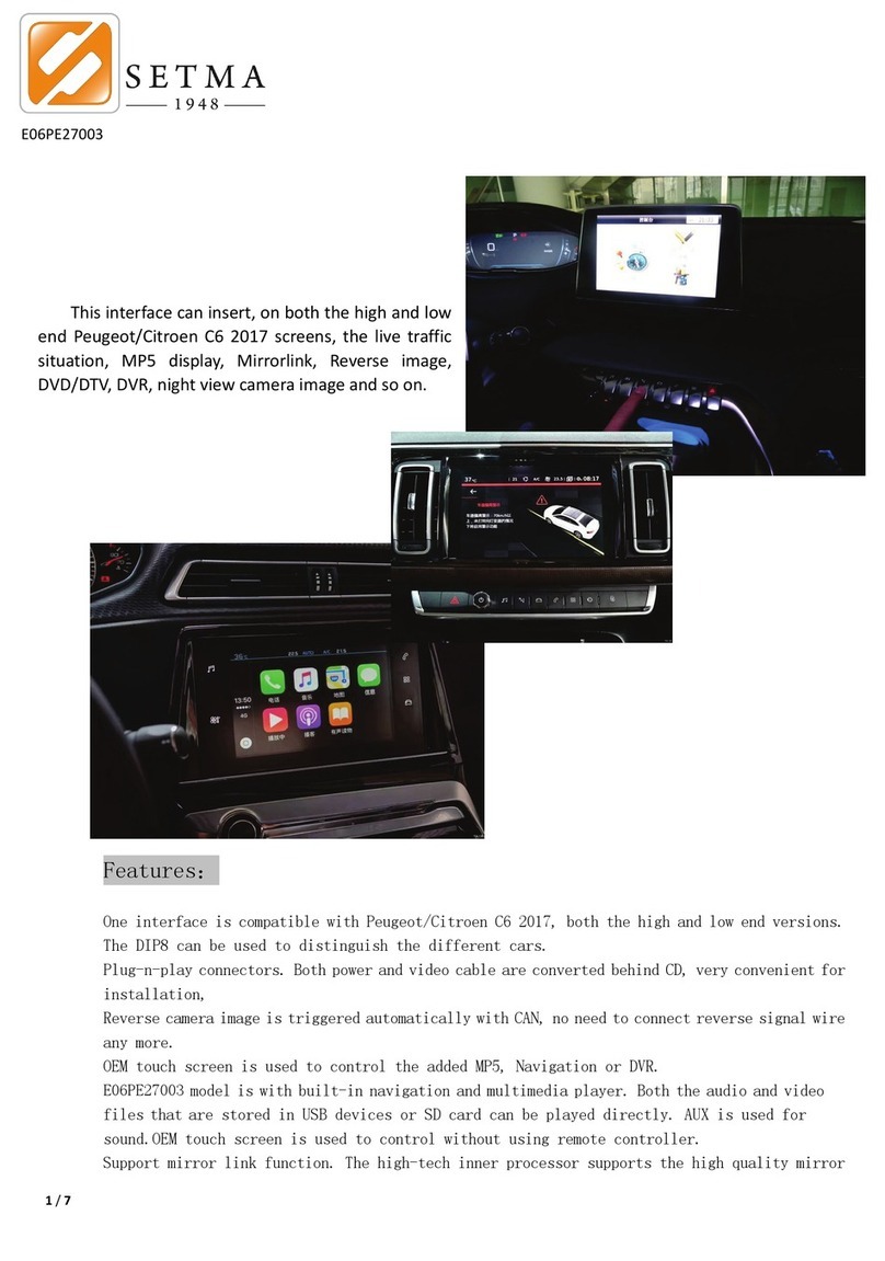
Setma E09ME22001 User manual

Manual Version: V20150901
E09ME22001
Installation Manual
Product Name: E09ME22001
Product Type: Dual Automatic Camera Interface (Front andRear Camera)
Application: Mercedes NTG4.5 systems, A, B, C, GL, GLK, ML models before 2014.

What's in the box:
Item
Qty
Description
Part No.
1
1
Camera Interface
2
1
LVDS Cable
3
1
CAN Interface Harness
4
1
CAN Box
5
1
Power Interface Harness
6
1
RCA Cable
7
1
Switch Button for Front Camera
8
2*
Reverse/Front Camera (*Optional*)

1. Description:
The E09ME22001 camera interface is the latest line of product from SETMA. It
will enable user toinstall Reverse Camera and Front Camera onto the cars which
do not have this function asOEM option.
It has three video inputs.
1. Reverse camera
2. Forward facing camera
3. Additional front camera( if user wants right and left front facing camera.
This function is *coming soon*)
The Reverse and Front camera have been measured accurately according
to the tire width of Cadillac SUV and Sedans. Making it very reliable and
accurate.
Reverse Guidelines shown on
Mercedes GLK300.
Move according to data from steering
wheel position.
Front Camera shown on Mercedes
GLK300.
Triggered Automatically after moving
out from Reverse gear to Drive.

2. Camera Functions:
The Reverse Camera is automatically triggered when engaging the reverse
gear of the car. The display is also equipped with moving reverse guidelines
which help guide the driver while reversing the car.
The Front Camera is automatically triggered after the person is in reverse
gear and engages Drive gear will automatically turn on to assist the driver
while parking. It will stay on for 10 Seconds and then the screen will
automatically turn back to the OEM display.
The User can also switch to the front camera using a push button switch.
This can be used in cases when the driver is parking the car without having
to engage the reverse gear for example in situations where the driver is
parking in a garage.
The User can also switch to the front camera by pressing and holding for 3
seconds the "C" button next to the controller knob.
The Guidelines are accurate as CAN code is used to generate them using
the steering wheel position as a reference.
This interface is suitable for both 7 Inch high resolution (800*480) screens
(DIP7 set UP and DIP8 set UP) and 6 Inch Smaller low resolution (480*240)
screens (DIP7 set UP and DIP8 set DOWN). The connection is the same for
both screens.

2.Installation:
Installation of this interface is very easy as it is completely plug and play. There is
no need to open the radio to insert any PCB etc.
Each Mercedes car model has a different process to open the dashboard
panel. (Please check the Car manufacturers manuals to know how to open
the dashboard and access the panels).
Once the back panel of the LCD is accessed it will have a 4Pin LVDS round
connector remove this and insert our cable here. The removed cable should
be inserted to our interface box. (Yellow Arrow)
The Power Harness will be removed from behind the CD and inserted to the
Power Harness provided with the interface. The Power harness plug
provided with the interface will be inserted in the place the original plug
was removed. The third plug will be connected to the CAN Box to provide
power to the interface.
*NOTE: Make sure that the power harness has been connected securely if not connected
properly there may be problems in power being sent to the interface .
4Pin LVDS CABLE

The CAN Box will be connected to the Interface using the power cable provided.
The Camera can be connected using the Video RCA cable provided.
•Red: Backup camera Input.
•Yellow: Front camera Input.
•White: Second front camera Input(*Currently Not used).
•Grey: Not Used
Check the video inputs and check if the video is positioned correctly. If not please
use the OSD menu to configure the size of the displayed picture.

3. Connection Diagram:
External Switch
LVDS USB
Connect to
CTRL
RCA Cable
for Camera
DIP settings
Power
Connect to

4. Camera Connection:
The Reverse Camera will be connected as normal. As it will get the
switching voltage from the CAN BOX.
The Front Camera will get power from the extra cable on the CTRL Plug.
This will give ON/OFF trigger voltage to the front camera.
The front camera and back camera will be connected using the RCA cable
provided.
Note:There are three video inputs on the RCA cable please make sure to not use video input 2
for any other video source. Also please turn the video source off from the DIP settings. This will
cause problems in auto trigger for the front camera.
This will be connected
to the front camera.
CTRL Plug

How to Connect Front Camera:
Connection for the front camera will be made as shown above.
The Backup Camera is connected as normal.
Camera RCA plug connects
to Yellow on INTERFACE
RCA plug
Power for camera
connects to wire on
interface power plug
Connect to Interface

5. DIP Settings:
DIP Down= ON DIP UP= OFF
DIP
ON
OFF
Default
1
No function
No function
UP(OFF)
2
Front camera installed
Front camera not installed
DOWN(ON)
3
No function
*will be used in future version
No function
UP(OFF)
4
No function
No function
UP(OFF)
5
Reverse camera installed
Reverse camera not
installed
DOWN(ON)
6
Auto-Trigger with 10s timer
enabled for front camera
Auto-Trigger with 10s
timer disabled for front
camera
(*Only manual switch will be
used if function is off)
DOWN(ON)
7
No function
No function
UP(OFF)
8
6 inch screen selected
7 inch screen selected
DIP7&DIP8=UP(OFF)
6. Power Definition for 6Pin power connector between CANBOX and Interface:
YELLOW
:
12V power supply (Battery)
RED: ACC
(
=12V when key in ignition state
):
when=12V,the interface works.
BLACK:Ground to Chassis。
GREEN:Can box generated reverse trigger signal [when =12V the reverse video is enabled], this wire is automatically
generated by CAN bus.
WHITE: This wire is the switch signal, when the user presses the touch panel for >1 second, this wire goes to 5V, then the
interface switches.
GRAY:CAN box’s communication data with guideline angle.

7. OSD Menu (new features) :
8.Parameters:
No.
Name
Parameter
1
Front Cam Video , Reverse Cam
video
0.7Vpp with 75 ohm impedance
NTSC/PAL/SECAM automatic switch
2
Reverse Control wire
>5V will force into camera mode.
these wires can tolerate 12V for <10 seconds.
3
Normal Power consumption
4.8W
4
Standby current
< 10uA
5
Reverse trigger threshold
>5V trigger
6
Work temperature
-40°C to +85°C
7
Dimensions
11.2*9.0*2.2cm
**For more assistance please contact the sales team.**
Choose if reverse camera is installed
on SUV/Sedan to get more accurate
Reverse Guidelines
Choose to turn on reverse guidelines
or turn off
Table of contents
Other Setma Car Video System manuals
