Version 29.10.2019 HW: CAM(V98)/UP(V20) CI-RL4-MIB-TR
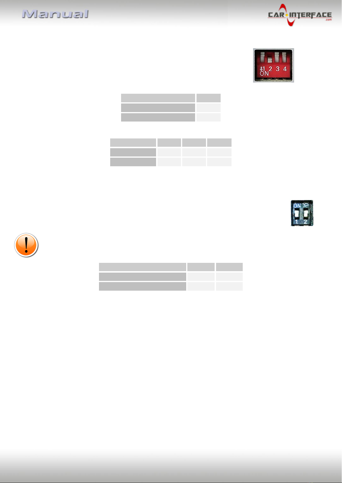
1.4.1. Activating the front camera (dip 1)
If set to ON, the interface switches for 10 seconds from the rear-view camera to the front
camera input after having disengaged the reverse gear. In addition, a manual switch-over to
the front camera input is possible via keypad (short press) from any image mode.
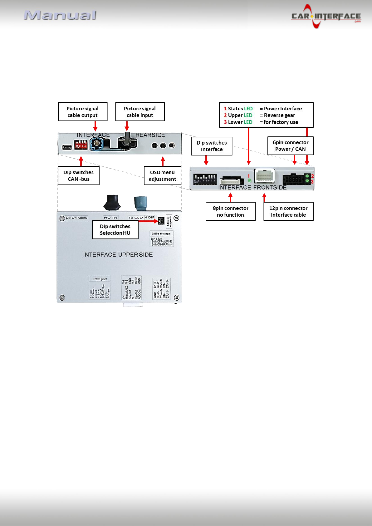
Description of the power supply output: see chapter “Power supply output”.
1.4.2. Enabling the interface’s video inputs (dip 2-3)
Only the enabled video inputs can be accessed by switching through the interface’s video
sources. It is recommended to enable only the required inputs. So the disabled inputs will be
skipped while switching through the video interfaces inputs.
Note: Dip 4 is out of function and have to be set to OFF!
1.4.3. Rear-view camera setting (dip 5)
If set to OFF, the interface switches to factory picture while the reverse gear is engaged to
display factory rear-view camera or factory optical park system picture.
If set to ON, the interface switches to its rear-view camera input while the reverse gear is
engaged.
1.4.4. Monitor selection (dips 6-8)
Dips 6, 7 and 8 customize the monitor-specific video settings. For the according monitor, use
the dipswitch combinations shown in the table below.
Sometimes the mentioned settings vary even within head units of the same version, caused
by different monitor specifications. In case of a non-optimal displayed picture with the
mentioned dip settings, we recommend to try each other possible dip switch combination of
dips 6, 7 and 8 while a working video source is connected to the chosen input of the
interface. One of the combinations will show the best picture size and quality (some may
give no picture). It is possible to first hot plug through the dip combinations.
If there is no change of picture visible after trying all options, retry and disconnect the 6pin
plug at the interface box between every change of the dip setting.
Empirical value:
8.8inch monitor Audi (Alpine)
10.1inch monitor Audi (Alpine)
8.8inch monitor Audi (Harman)