Setra Systems SRH User manual
Model SRH
Operating Instructions
Setra Systems, Inc.
159 Swanson Road, Boxborough, MA 01719
800.257.3872 • www.setra.com

2

3
Table of Contents
1.0 General information ....................................................................................................... 4
2.0 Mechanical installation ................................................................................................ 4
2.1 Environment............................................................................................................... 4
2.2 Wall mount.................................................................................................................4
2.3 Duct mount ................................................................................................................ 5
2.4 Outside air mount...................................................................................................... 5
3.0 Electrical installation ..................................................................................................... 6
3.1 Wiring .........................................................................................................................6
4.0 Calibration ......................................................................................................................9
4.1 Remove/Install the sensor tip................................................................................... 9
4.2 Ordering information - replacement sensor assembly*........................................ 10
5.0 Specications...............................................................................................................11
6.0 Dimensional drawings .................................................................................................12
7.0 Duct mount installation ...............................................................................................13
8.0 Returning products for repair......................................................................................15
9.0 Warranty & limitation of liability..................................................................................15
4
1.0 General information
Every SRH humidity sensor product is tested and calibrated before shipment. Setra’s Humidity
Sensor family consists of a wall mount, duct mount, and outside air unit. This product line
expands the solution opportunities for the HVAC/building automation market and other
relative humid ity monitoring applications. All models utilize a eld-replaceable sensor module,
NIST traceability, accuracies of ±2%, ±3%, ±5%, active or passive temperature sensing, and a
durable capacitive sensor capable of full-scale 0 to 100% RH measurement.
2.0 Mechanical installation
2.1 Environment
The operating temperature limits of the SRH model are as follows:
Operating Temperature Range -40°F to 140°F (-40 to 60°C)
Storage Temperature -40°F to 158°F (-40 to 70°C)
2.2 Wall mount
It is important to nd a place within a room where the transmitter can be exposed to
unrestricted air circulation that will represent the average humidity and temperature within
that space. Try to avoid any locations that may be exposed to fumes, extreme temperatures,
and high moisture content. Also, make sure the location is on an indoor wall that is about
4 to 6 feet above the floor. For ease of mounting, the wall mount humidity transmitter was
designed to install onto a standard single gang electrical switch box or directly onto a wall.
Model SRH
Wall Mount Unit
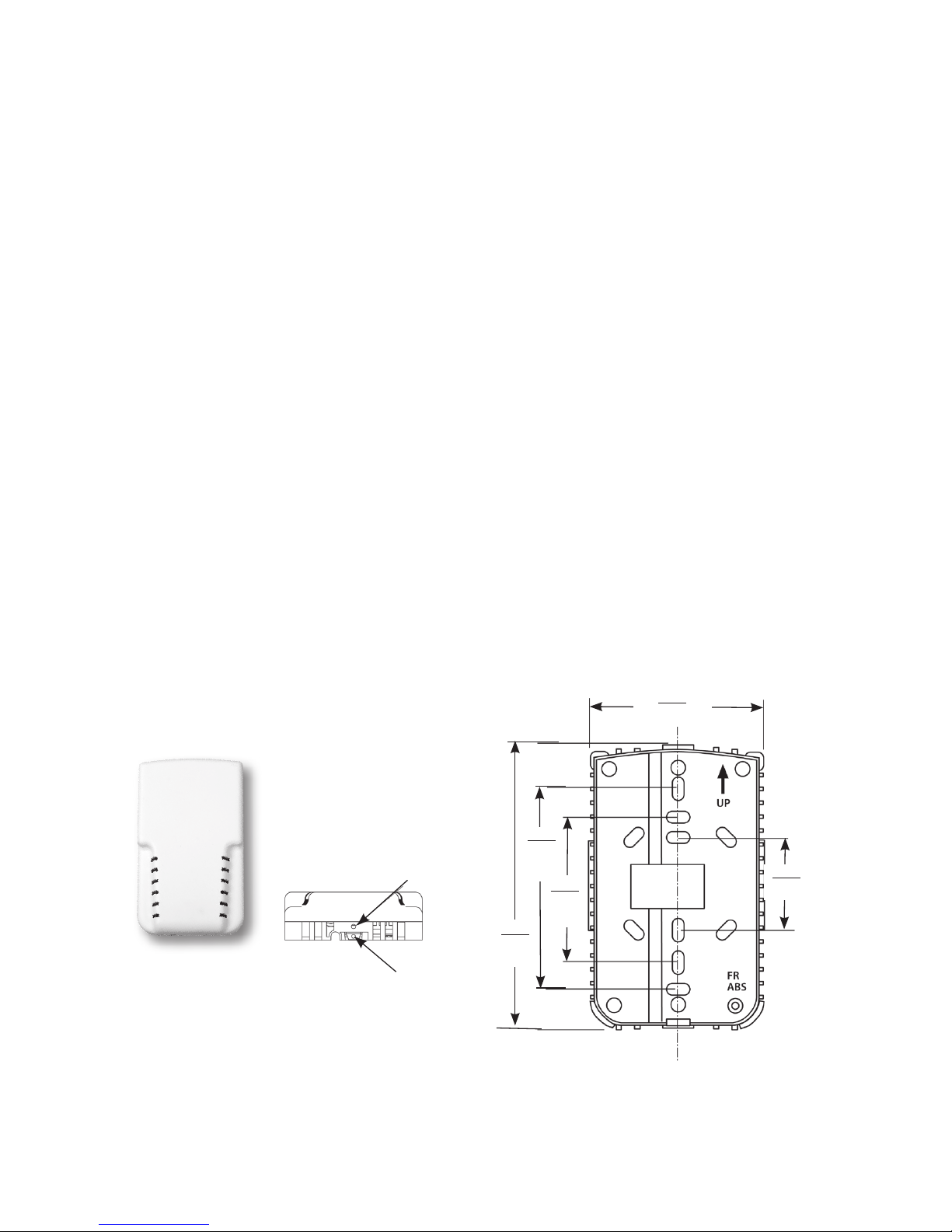
2.81
71.50
3.30
84
4.69
119
1.41
36
Wall Mount - Back Plate
2.37
60
To open wall unit, back out the
security set screw (if used), then
press the security latch inward
and lift-up cover.
Security Latch
Security
Screw
Front View
Top View
in.
(mm)

5
Wall Mount - Back Plate
2.3 Duct mount
For proper operation, it is necessary to locate the transmitter in the center of a section of
duct that receives adequate air flow. Conversely, it must be free of fans, corners, heating/
cooling coils, or any other equipment/ environmentals that could adversely affect relative
humidity measurement. Insert sensing probe through hole (5/8” dia. minimum) and attach full
assembly via the two mounting holes on each side.
2.4 Outside air mount
The outside air conguration is supplied with a mounting bracket and two 10-16 x 1/2’ hex
head screws. Locate a position on the building that is clear of exhaust ducts, high exposure
to the sun, direct rain, or other outdoor factors that could adversely affect the operation of the
unit. Ideally, a sheltered area (under an eave) on the north side of the building is best to protect
from the above effects.
5.1
130
3.72
94
Model SRH
Duct Unit
shown w/sensing
probe
Duct mount base
1.11
28
X2
0.180
5
in.
mm
2.69
68
Outside air mounting plate
Model SRH
Outside air unit
shown w/porous weather shield
in.
mm
4.05
103
5.00
127
X2
0.550
14
2.81
71
3.31
84
1.75
44
X8
0.325
8.3
X2
0.154
4
Table of contents
Other Setra Systems Accessories manuals


