Seyeon Technology FlexWATCH FWR424 User manual


FWR424/FWR228 NVR User Manual M4071-00
M4071-00 2Seyeon Tech Co., Ltd
Safty Warnings and Cautions
Before connecting and operating your device, please be advised of the following tips:
Make sure to unplug the power cord while installing the unit
Do not connect several devices to one power adaptor as adaptor overload may cause overheating, electric shock or fire
hazard.
The interior of the unit should have high-voltage areas so do not open the top cover, disassemble, repair or modify.
Ensure unit is installed in a well-ventilated, dust-free environment and NOT in high-humidity environment
Input voltage for operation of the unit shall be within the specified voltage range (100 ~ 240V AC) ±10% Maximum, do not
use the outlet for connecting the high power consumption products such as the heater, air conditioning etc.
In case of data storage device (HDD) reaches to the end of its useful life, the recording or playback may not be available so
the periodic inspection is highly recommended. We are not responsible for the damaged data due to user’s carelessness.
The default ID and Password is “root”/”root” (case sensitive). To prevent identity theft damage, highly recommend to
change your password periodically. User has responsibility for security and other problems caused by careless password
management.
The installation environment needs to be a well-ventilated area and away from direct sunlight or hot area.
Please avoid installation of unit where close to strong magnetic force, radio wave or wireless device such as Radio / TV.
Do not place heavy objects on the unit and be careful no foreign substances in the unit.
A strong shock or vibration may cause damage of unit
If a strange sound or smell exists, unplug the unit immediately and contact your dealer or manufacturer
Do not use the unit while the cover is open and Needs a proper air circulation system in a system operation room.
Otherwise the unit might be damaged due to internal and/or elements of unit temperature rise.
Make sure that connect the power cord to a grounded wall outlet. Otherwise it may cause an electric shock or injury.
Inside of unit there should have sharp edges. Always be careful to avoid any injury when top cover has been opened for
installation or replacement of HDDs.

FWR424/FWR228 NVR User Manual M4071-00
M4071-00 3Seyeon Tech Co., Ltd
Copyright Information
Copyright 2016 Seyeon Tech Co., Ltd. All rights reserved. Use of this product and manual is subject to license. Information in this
document is subject to change without notice. FlexWATCH® is registered trademark of products of Seyeon Tech Co., Ltd. All other
brand and product names mentioned in this document are registered trademarks or trademarks of their respective holders. The
Software supplied with these Products is provided under license from Seyeon Tech Co., Ltd.
GNU General Public License Information
This product includes certain open source or other software originated from third parties that is subject to the GNU General
Public License (GPL), GNU Library/Lesser General Public License (LGPL), and different and/or additional copyright licenses,
disclaimers, and notices.
The exact terms of GPL, LGPL, and some other licenses are provided to you with this product. Please refer to the exact terms of
the GPL and LGPL at http://www.fsf.org (Free Software Foundation) or http://www.opensource.org (Open Source Initiative) regarding
your rights under said license. In accordance with the terms of the GPL and LGPL, you may obtain a copy of the relevant source code
by sending your request to sales@flexwatch.com. Subject to GPL, you may re-use, re-distribute and modify the GPL source code.
Note that with respect solely to the GPL Software, no warranty is provided. We do not offer direct support for the distribution.
This offer is valid for up to three years from the date of original purchase of the Product.

FWR424/FWR228 NVR User Manual M4071-00
M4071-00 4Seyeon Tech Co., Ltd
Contents
1. Key Features.......................................................................................................................................................................................7
2. Product Description ...............................................................................................................................................................................8
2.1 Package Contents.............................................................................................................................................................................8
2.1.1 FWR424 Model .........................................................................................................................................................................8
2.1.2 FWR228 Model .........................................................................................................................................................................8
2.2 Part Names and Functions (Front) ...................................................................................................................................................9
2.2.1 FWR424 Model .........................................................................................................................................................................9
2.2.2 FWR228 Model .......................................................................................................................................................................10
2.3 Part Names and Functions (Rear)...................................................................................................................................................11
2.3.1 FWR424 Model .......................................................................................................................................................................11
2.3.2 FWR228 Model .......................................................................................................................................................................12
3. Installation ...........................................................................................................................................................................................13
3.1 Hard Disk Drive (HDD) installation .................................................................................................................................................13
3.1.1 FWR424 Model .......................................................................................................................................................................13
3.1.2 FWR228 Model .......................................................................................................................................................................14
3.2 Connect to Monitor........................................................................................................................................................................15
3.3 Connect Input Devices ...................................................................................................................................................................15
3.4 Connect to Network.......................................................................................................................................................................15
4. Starting NVR.....................................................................................................................................................................................16
4.1 Powering On...................................................................................................................................................................................16
4.2 Setting Date/Time ..........................................................................................................................................................................17
4.3 Setting of NVR IP ............................................................................................................................................................................19
4.4 Registering IP Devices ....................................................................................................................................................................21
5. Configuration of NVR System...........................................................................................................................................................24
6. Live Viewer.......................................................................................................................................................................................25
6.1 Live View Tool Bar ..........................................................................................................................................................................26
6.2 Server Control Bar..........................................................................................................................................................................27
6.2.1 Server Tree ..............................................................................................................................................................................27
6.3 Group Control Bar..........................................................................................................................................................................28
6.3.1 Creating/Modifing/Deleting Group in Live Viewer Page.........................................................................................................28
6.3.2 Adding IP device......................................................................................................................................................................29
6.4 PTZ Control Bar ..............................................................................................................................................................................30
6.5 Audio Control Window...................................................................................................................................................................32
7. Player A (Time Search) .....................................................................................................................................................................33
7.1 Search Tool Bar...............................................................................................................................................................................34
7.2 Server Control Bar..........................................................................................................................................................................35

FWR424/FWR228 NVR User Manual M4071-00
M4071-00 5Seyeon Tech Co., Ltd
7.3 Group Control Bar..........................................................................................................................................................................35
7.3.1 Creating/Modifing/Deleting Group ........................................................................................................................................36
7.3.2 Adding IP device into a Group.................................................................................................................................................37
7.4 Playback Window/Bar....................................................................................................................................................................38
7.5 Date (Calendar / Timeline) Window/Bar........................................................................................................................................39
7.5.1 Calendar..................................................................................................................................................................................39
7.5.2 Timeline ..................................................................................................................................................................................39
8. Player B (Condition Search)..............................................................................................................................................................41
8.1 Search Tool Bar...............................................................................................................................................................................42
8.2 Server Control Bar..........................................................................................................................................................................43
8.3 Group Control Bar..........................................................................................................................................................................43
8.3.1 Creating/Modifing/Deleting Group in Player A.......................................................................................................................44
8.3.2 Adding IP device into a Group in Player A...............................................................................................................................45
8.4 Playback Window...........................................................................................................................................................................46
8.5 Condition Window .........................................................................................................................................................................47
8.5.1 Condition Search.....................................................................................................................................................................47
9. Configuration Page...........................................................................................................................................................................50
9.1 Menu Bar .......................................................................................................................................................................................51
9.2 IP-Device Configuration..................................................................................................................................................................51
9.2.1 Simple Registration .................................................................................................................................................................52
9.2.2 ADD (Manual IP device Registration) ......................................................................................................................................56
9.2.3 Edit (Editing IP Device Information) ........................................................................................................................................58
9.2.4 Delete (Deleting IP Device ).....................................................................................................................................................60
9.3 Camera Configuration ....................................................................................................................................................................61
9.3.1 Camera Name .........................................................................................................................................................................61
9.3.2 Simple Recording Setup ..........................................................................................................................................................62
9.4 Preference Configuration ...............................................................................................................................................................64
9.4.1 System Name ..........................................................................................................................................................................64
9.4.2 System Time............................................................................................................................................................................65
9.4.3 Admin Password......................................................................................................................................................................65
9.4.4 Access Level ............................................................................................................................................................................66
9.4.5 IP Address................................................................................................................................................................................66
9.4.6 Web Port .................................................................................................................................................................................67
9.4.7 HDD Setup...............................................................................................................................................................................67
9.4.8 Common DI/DO (Built-In Alarm) .............................................................................................................................................70
9.5 Utility..............................................................................................................................................................................................72
9.5.1 Update.....................................................................................................................................................................................72
9.5.2 No Camera Image....................................................................................................................................................................73

FWR424/FWR228 NVR User Manual M4071-00
M4071-00 6Seyeon Tech Co., Ltd
9.5.3 Factory Default........................................................................................................................................................................73
9.5.4 Reboot.....................................................................................................................................................................................74
9.5.5 Log Out....................................................................................................................................................................................74
9.5.6 System Information.................................................................................................................................................................74
9.5.7 Language.................................................................................................................................................................................75
9.6 Remote Control..............................................................................................................................................................................76
9.6.1 Camera Setting........................................................................................................................................................................76
9.6.2 Motion Detection....................................................................................................................................................................78
10. Appenddix..........................................................................................................................................................................................78
10.1 Specification.................................................................................................................................................................................78
10.1.1 FWR424 Model .....................................................................................................................................................................78
10.1.2 FWR228 Model .....................................................................................................................................................................80
10.2 Product Overview.........................................................................................................................................................................81
10.2.1 FWR424 Model .....................................................................................................................................................................81
10.2.2 FWR228 Model .....................................................................................................................................................................82

FWR424/FWR228 NVR User Manual M4071-00
M4071-00 7Seyeon Tech Co., Ltd
1. Key Features
FWR424/FWR228 NVR is an integrated Video Surveillance Device based on the Embedded Linux OS, and it has the following major
features.
Connect up to 32 channels of IP equipment, including IP cameras and video server/encoder products from various
manufacturers, for real-time video and audio surveillance, storage and playback, backup, and re-transmission of video and
audio.
Supports a various manufactureres cameras, including:
3S, AGNI, AVTech, Acti, Appro, Arecont, Axis, CNB, ICanTek, IQInVision, K-IPCAM, Mobotix, Panasonic, Proprietary, Samsung
Electronics, Hanwha/Samsung Techwin, TpLink, Truen, Vivotek
* For more information about supported cameras, please contact your supplier or our technical support team.
Supports HDMI and VGA simultaneous output and supports Full HD (1920x1080) monitor.
Supports up to 10 megapixel IP cameras.
Supports MJPEG, MPEG4 and H.264 compression type.
Each channel supports dual stream and triple streams.
Supports Alarm In/Out.
* The number of Alarm In/Out ports supported depends on the NVR model number.
Supports Bi-Directional Audio (2-Way Audio).
Supports various PTZ protocols.
Supports various recording methods such as Continues, Motion Detection, Various Events, and Schedule.
IP assign and basic setting can be done without client PC, when connecting and using FlexWATCH® IP Camera and Video Server
(Encoder) models.
Supports two Network ports, WAN and LAN, for building secure private IP network and bandwidth management.
Supports NAT function, allowing direct connection to each camera connected via NVR.
No special monitoring or management programs are required. It can be monitored and managed
with the built-in Internet Explorer in Microsoft Windows®.
For more information on the features and operation of this unit, refer to the user manual on the CD provided with this product
and the latest information provided on the FlexWATCH® website (www.flexwatch.co.kr).
FWR424/FWR228 NVR User Manual M4071-00
M4071-00 8Seyeon Tech Co., Ltd
2. Product Description
2.1 Package Contents
Please unwrap the product, and place the product on a flat place or in the place to be installed.
Please check the following contents are included in addition to the main unit
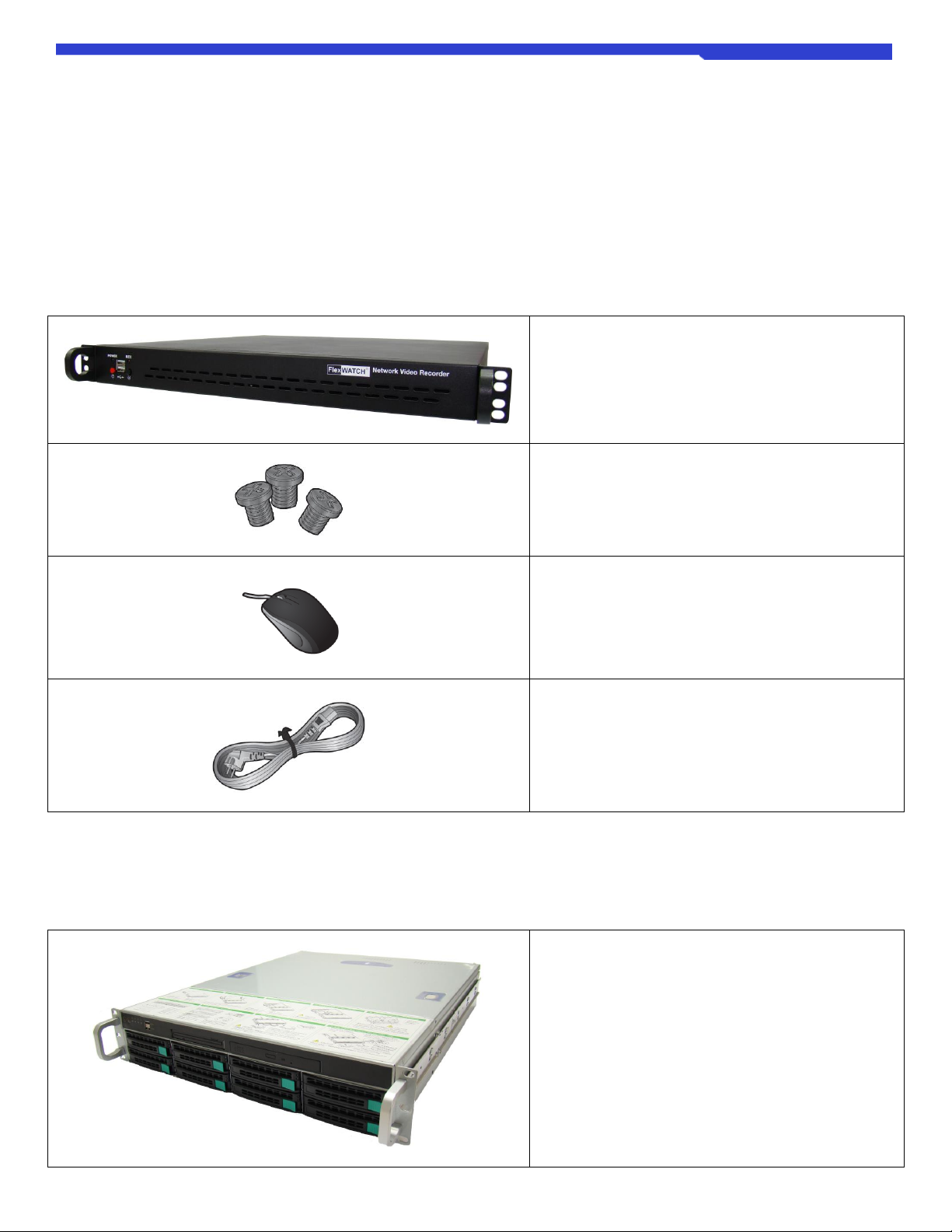
2.1.1 FWR424 Model
FWR424 Network Video Recorder x 1EA
Screw for Hard disk fixing x (more than) 16PCS
Mouse x 1EA
Power Cable x 1EA
2.1.2 FWR228 Model
FWR228 Network Video Recorder x 1EA

FWR424/FWR228 NVR User Manual M4071-00
M4071-00 9Seyeon Tech Co., Ltd
Screw for Hard disk fixing x (more than) 32PCS
Mouse x 1EA
Power Cable x 1EA
2.2 Part Names and Functions (Front)
2.2.1 FWR424 Model
Image
Name
Description
POWER LED
The LED lights up when the NVR is powered up.
REC LED
The LED lights up when data is read from or written to the hard disk.
Power Switch
Power ON / OFF switch of NVR.
Press the switch once to power the NVR. To turn the power off, press and hold the button
for more than 6 seconds.
Factory Default Switch
Factory reset switch. Press and hold this button for more than 6 seconds to start the Factory
Default process.
* Be careful, all settings including network settings will be returned to the factory default
settings.
USB Ports (x2)
It is two USB ports used to connect USB flash drive for backup or input devices such as
keyboard, mouse.
Ventilation hole
Vent holes for venting heat inside the NVR.
* Be careful that there are no obstacles around the installed NVR for smooth air circulation.
FWR424/FWR228 NVR User Manual M4071-00
M4071-00 10 Seyeon Tech Co., Ltd
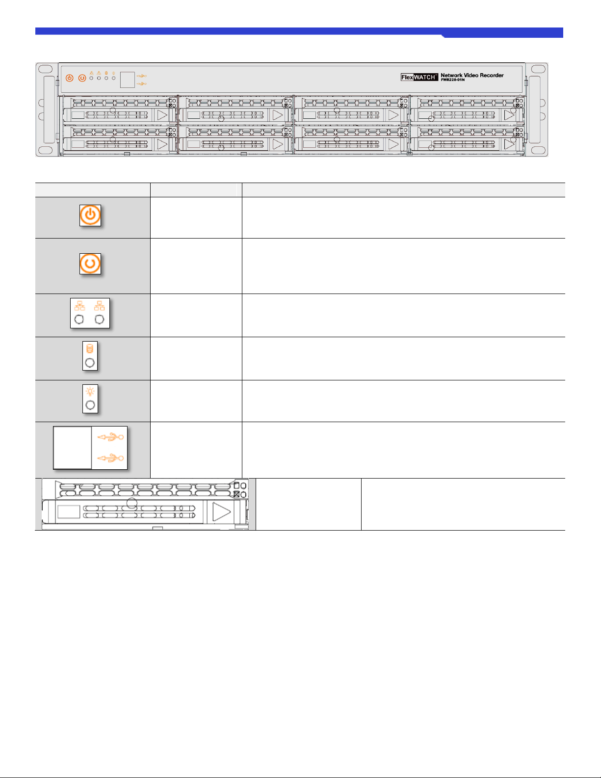
2.2.2 FWR228 Model
Image
Name
Description
Power Switch
Power ON / OFF switch of NVR.
Press the switch once to power the NVR. To turn the power off, press and hold the button
for more than 6 seconds.
Factory Default
Switch
Factory reset switch. Press and hold this button for more than 6 seconds to start the
Factory Default process.
* Be careful, all settings including network settings will be returned to the factory default
settings.
Network Status LED
The left side LED shows the status of the WAN port, and the right side LED shows the
status of the LAN port.
REC LED
The LED lights up when data is read from or written to the hard disk.
POWER LED
The LED lights up when the NVR is powered up.
USB Ports
(x2)
2 It is two USB ports used to connect USB flash drive for backup or input devices such as
keyboard, mouse.
HDD Drive Bay
(x8)
It is a hot swappable hard disk bay that can hold a
total of 8 hard disks.

FWR424/FWR228 NVR User Manual M4071-00
M4071-00 11 Seyeon Tech Co., Ltd
2.3 Part Names and Functions (Rear)
2.3.1 FWR424 Model
Image
Name
Description
Power
Power input port for power cable connection.
Available voltage: 100 ~ 240VDC / Available power frequency: 50 ~ 60Hz
Console (RS232)
RS232 console port. It is a port for installing the program when the device is manufactured.
DI / DO
Alarm In / Out port consists of 4 DI (Digital Input) and 1 DO (Digital Out).
WAN
It is a port for external network connection of NVR. IP cameras and video servers (Encoder)
in the external network also can be registered in the NVR via the WAN port.
It is recommended to use LAN port for IP camera and video server
(Encoder) connection for security enhancement and proper distribution of
bandwidth.
LAN
It is a private network port for connection of IP camera and video server.
Audio In / Out
Audio input / output port of RCA standard.
VGA Out
-Sub type VGA Video Out port, which supports 1080P Full-HD resolution output device
(monitor, etc.).
If the display device (monitor, etc.) does not support Full-HD because the
output resolution of the NVR is fixed to Full HD (1080P), the image will be
output but a part of the screen may not be displayed.
HDMI
HDMI Video Out port supports 1080P Full-HD resolution output device (monitor, etc.).
Since the output resolution of the NVR is fixed to Full HD (1080P), if the
display device (monitor, etc.) does not support Full-HD, no image is output.
USB 3.0
The USB 3.0 port supports fast data transfer rates and is ideal for data backup.
USB 2.0
It is a USB ver.2.0 port for connection of input devices such as keyboard, mouse, or USB
flash drive for data backup.
RS485
It is an RS485 port used to connect with PTZ or external device.
FWR424/FWR228 NVR User Manual M4071-00
M4071-00 12 Seyeon Tech Co., Ltd
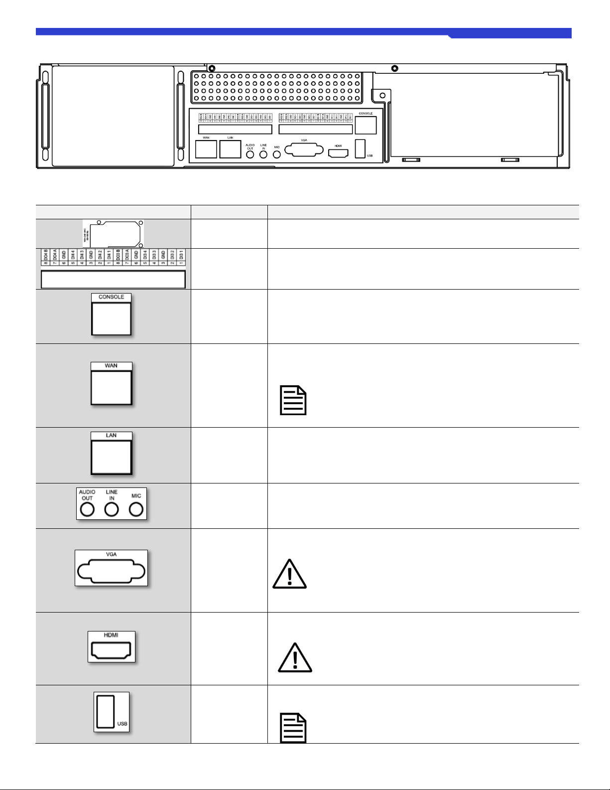
2.3.2 FWR228 Model
Image
Name
Description
Power
Power input port for power cable connection.
Available voltage: 100 ~ 240VDC / Available power frequency: 50 ~ 60Hz
DI / DO
(Alarm)
Alarm In / Out port consists of 16 DI (Digital Input) and 4 DO (Digital Out).
RS232
RS232 console port. It is a port for installing the program when the device is
manufactured.
WAN Port
It is a port for external network connection of NVR. IP cameras and video servers
(Encoder) in the external network also can be registered in the NVR via the WAN
port.
It is recommended to use LAN port for IP camera and video server
(Encoder) connection for security enhancement and proper
distribution of bandwidth.
LAN Port
It is a private network port for connection of IP camera and video server.
Audio In / Out
Audio input / output port of RCA standard.
VGA Out
D-Sub type VGA Video Out port, which supports 1080P Full-HD resolution output
device (monitor, etc.).
If the display device (monitor, etc.) does not support Full-HD because
the output resolution of the NVR is fixed to Full HD (1080P), the
image will be output but a part of the screen may not be displayed.
HDMI Out
HDMI Video Out port supports 1080P Full-HD resolution output device (monitor,
etc.).
Since the output resolution of the NVR is fixed to Full HD (1080P), if
the display device (monitor, etc.) does not support Full-HD, no image
is output.
USB Port
It is a USB port for connection of input devices such as keyboard, mouse, or USB
flash drive for data backup.
The USB 3.0 port supports fast data transfer rates and is ideal for
data backup.

FWR424/FWR228 NVR User Manual M4071-00
M4071-00 13 Seyeon Tech Co., Ltd
3. Installation
3.1 Hard Disk Drive (HDD) installation
The recording data index is created on the hard disk connected to SATA port 1 of the NVR. Therefore, when installing two
or more hard disks, HDD must be installed from SATA Port #1. Changing the port connection of the active HDDs may result
in data loss. If it is necessary to change the SATA port connected to the HDD inevitably, please make sure to format the
hard disk after changing it.
To minimize the risk of data loss due to a damaged HDD or HDD malfunction, back up important data as often as possible.
Please backup important data before HDD formatting.
Make sure to unplug the power cord from the wall outlet before HDD installation to prevent possible product damage or
injuries such as electric shocks.
3.1.1 FWR424 Model
To install the hard disk, follow the instructions below.
①Unscrew the four screws as shown below and remove the top cover.
(Locations of top cover fixing screw.)
②Mount a HDD in the HDD bracket and tightening it using the screws provided.
< HDD Installation Bracket>
FWR424/FWR228 NVR User Manual M4071-00
M4071-00 14 Seyeon Tech Co., Ltd
③Attach the HDD onto HDD installation bracket and assemble to the NVR using screws provided.
④Connect SATA Cable and Power Cable to the HDDs.
⑤Assemble the top cover with screws.
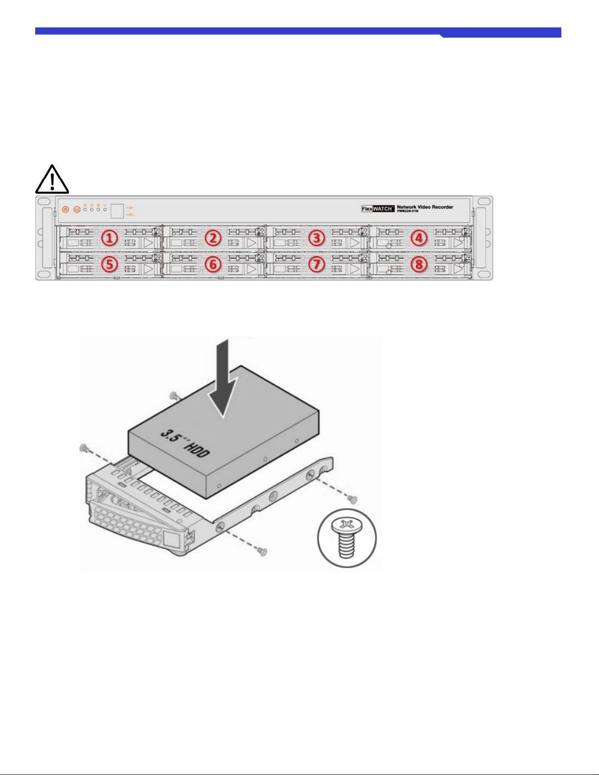
3.1.2 FWR228 Model
HDD must be installed in the following order for using RAID feature.
①Press the release button on the front of the hard disk carrier, and then pull the handle to remove it from the NVR.
②Fix the hard disk to the hard disk carrier using the supplied screws as shown below.
③Insert the carrier with the hard disk into the hard disk slot on the front of the NVR and push the carrier until it touches the
backplane.
④Push the handle of the carrier to fix it.

FWR424/FWR228 NVR User Manual M4071-00
M4071-00 15 Seyeon Tech Co., Ltd
3.2 Connect to Monitor
Full HD (1080P) Monitor must be used.
If the monitor does not support Full-HD (1080P), screen may not display properly.
Connects monitor to the VGA or HDMI input ports according to the connection method of the monitor.
3.3 Connect Input Devices
USB Mouse must be connected to the NVR for system operating. USB Keyboard also can be used for ease of use.
USB Keyboard and Mouse can be connected any of USB port on NVR.
However, USB 3.0 port is recommended to use for a backup purpose.
Virtual keyboard will be displayed on the screen as shown below if keyboard is not connected.
3.4 Connect to Network
NVR has built-in WAN and LAN network ports.
WAN port is used for remote access.
Connect to an internet available network or a network where client PC belongs to.
WAN port may not been used if remote access is not necessary.
WAN port also can be used for IP camera and Encoder connections.
However, we recommend using LAN port for the connections,
for enhanced security and bandwidth management.
LAN port is used to build a private network for the connections of IP camera and video servers.
Network Switch is required to connect IP Cameras and/or Video Servers through this port.

FWR424/FWR228 NVR User Manual M4071-00
M4071-00 16 Seyeon Tech Co., Ltd
4. Starting NVR
It describes the most basic ways to start setting the NVR system.
4.1 Powering On
①Connect the Power Cable on the rear panel of the NVR.
②Turn on the Power switch on the rear panel of the NVR.
③Press power button one time on front panel of the NVR.
④NVR will start boot with power LED and beeps.
< NVR Booting Screen >
⑤When NVR has finished booting, Live View screen will be displayed as shown below.

FWR424/FWR228 NVR User Manual M4071-00
M4071-00 17 Seyeon Tech Co., Ltd
4.2 Setting Date/Time
Applying the correct date and time is strongly recommended to avoid any confusion or errors caused by time difference
between the NVR system, IP device and client (remote access) PC.
①Click Congifuration icon ( ) at upper right corner on local screen.
②Login with ID and Password when login window appears.
Virtual keyboard will appear on screen if a USB keyboard is not attached as shown below.
Otherwise, use USB keyboard to input login ID and Password.
Default ID and Password is "root" for both. (Case sensitive)
③Go to
Preference Configuration -> System Time
on the menu bar.

FWR424/FWR228 NVR User Manual M4071-00
M4071-00 18 Seyeon Tech Co., Ltd
④Enter the current Date and Time when Setup System time
window appears.
⑤If necessary, click Change Time Zone to select Time Zone.
* System Reboot is required.
For more detail about NTP Service,
please refer to [Pg.60 8.4.2 System Time].
⑥Click OK to apply the changes and close the window.
After camera registration, the time will be displayed at the
top left corder of each channel on live screen
as shown on the right.

FWR424/FWR228 NVR User Manual M4071-00
M4071-00 19 Seyeon Tech Co., Ltd
4.3 Setting of NVR IP
WAN IP setting is not necessary if remote access is not required.
In this case, you may skip this manual section [3.4 Setting of NVR IP].
There are two ways to set IP address to the NVR as follows:
-Remote configuration through a Client PC.
-Configuration through the local monitor.
To remote configure through a Client PC, installation of IP Installer software (FlexWATCH® dedicated software) is required.
Please refer to IP Installer user manual linked below.
Korean: http://www.flexwatch.co.kr/board/download.asp?filepath=EasyGuide&filename=IP Installer Easy Guide.pdf
English: http://www.flexwatch.com/board/download.asp?filepath=EasyGuide&filename=IP Installer Easy Guide ENG.pdf
IP Installer software can be found in the enclosed CD or software download page at FlexWATCH® Web Site
(http://www.FlexWATCH.com/support/download/software.asp).
To configure thorugh the local monitor, please follow the steps below:
⑦Click Congifuration icon ( ) at upper right corner on local screen.
⑧Login with ID and Password when login window appears.
Virtual keyboard will appear on screen if a USB keyboard is not attached as shown below.
Otherwise, use USB keyboard to input login ID and Password.

FWR424/FWR228 NVR User Manual M4071-00
M4071-00 20 Seyeon Tech Co., Ltd
Default ID and Password is "root" for both. (Case sensitive)
①Go to
Preference Configuration -> IP Address
on the menu bar.
②Enter IP Information for the NVR System,
And then Click OK.
③Click OK to confirm.
④Changed IP address can be found on following page as shown below.
This manual suits for next models
1
Table of contents
Other Seyeon Technology Network Hardware manuals

Popular Network Hardware manuals by other brands

PairGain
PairGain HiGain Line Unit HLU-388 Quick installation guide

Cisco
Cisco 8011-2X2XP4L Hardware installation guide

Lenovo
Lenovo Storage N3310 User guide and hardware maintenance manual

Tadiran Telecom
Tadiran Telecom FlexSet 280 manual

Avaya
Avaya Cajun P550R Cli reference guide

Victron energy
Victron energy Venus GX manual


e-con Systems
e-con Systems See3CAM 130 user manual

MikroTik
MikroTik RouterBOARD Groove 2Hn Quick setup guide and warranty information

KTI Networks
KTI Networks KGS-2421 installation guide

LEGRAND
LEGRAND LMBC-600 manual

Polycom
Polycom Video Media Center VMC 1000 Getting started guide

Honeywell
Honeywell HDCD8TP user manual