Seymour AV Center Stage XD User manual

Copyright ©2009, Seymour Products LLC, www.seymourav.com, All rights reserved.
Electric Screen Contents ................................................................................................................... 2
Electric Screen Installation Instructions.............................................................................................. 5
Wall Mount..................................................................................................................................... 5
Ceiling Mount................................................................................................................................. 6
Gen4 4-wire and Somfy®Motor Control Options................................................................................ 9
Gen4 4-wire wall switched ONLY................................................................................................... 9
Gen4 4-wire motor control box options........................................................................................... 9
Gen4 4-wire connection............................................................................................................... 10
Gen4 4-wire IR control................................................................................................................. 10
Gen4 4-wire RF control................................................................................................................ 11
Gen4 4-wire motor control box wall-switched, or relay controlled................................................. 11
Gen4 nonstandard options........................................................................................................... 12
Somfy control............................................................................................................................... 12
Somfy 4-connector splitter ........................................................................................................... 12
Somfy IR control.......................................................................................................................... 12
Somfy RF control............................................................................................................................. 12
Gen4 Standard RF Motor Limits Setting (RF motors with LED dongle)............................................ 13
Gen4 Limits Setting Flowchart ..................................................................................................... 14
Gen3 Standard RF Motor Limits Setting (RF motors without LED dongle)....................................... 15
Gen3 Limits Setting Flowchart ..................................................................................................... 16
Gen4 RF remote replacement...................................................................................................... 17
Troubleshooting............................................................................................................................... 17
Waves.......................................................................................................................................... 17
“Ca-chunck” clanking sound when bar goes into case ................................................................. 18
Motor bogs down in the upper position before stopping ............................................................... 19
RF remote doesn’t work............................................................................................................... 19
GETTHESCREEN,
KEEPTHESOUND™
Copyright ©2009, Seymour Products LLC, www.seymourav.com, All rights reserved.
Electric Screen Contents
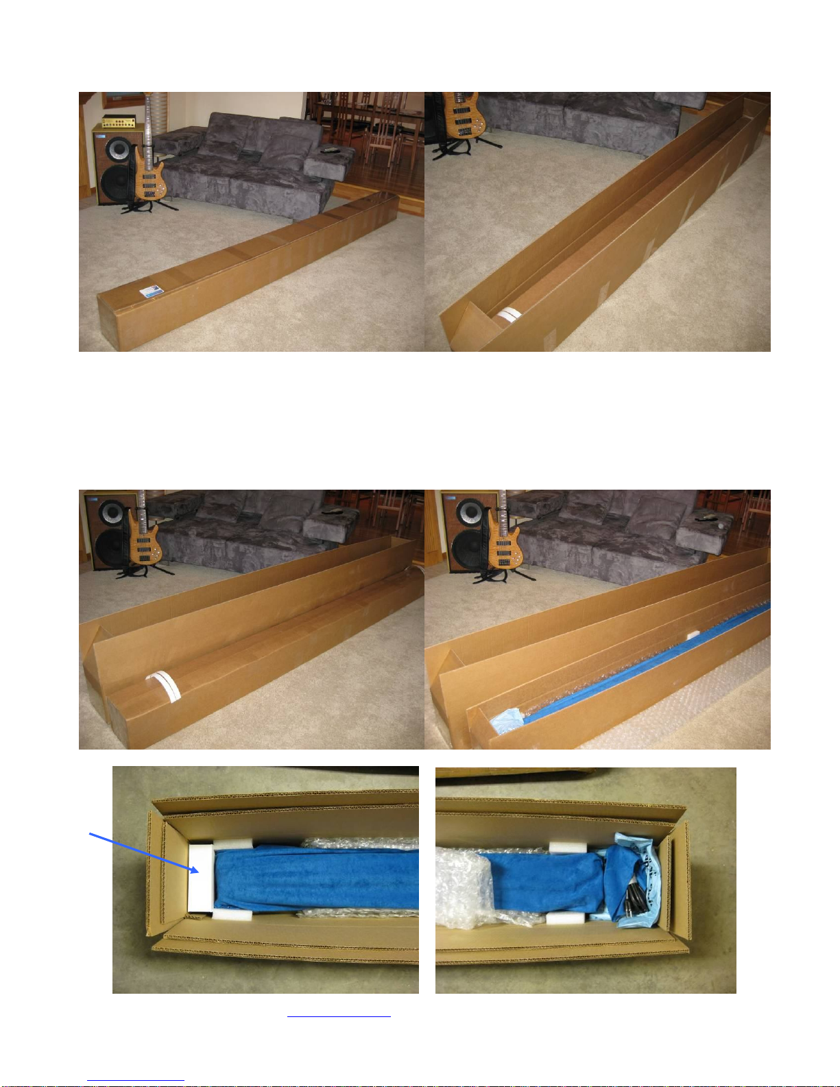
1) Pull the inner box out of the outer box using the white plastic pull straps that are mounted to the
inner box. Make sure you use both handles per side so they will adequately lift the
approximately 50 to 70 pound load. Open the inner box (yes, the straps will have to be peeled
off) and you’ll see the bubble wrap top lining and a white box that contains the screen
accessories. Remove the bubble wrap top layer, the accessories box, and the screen with its
velvet bag still on. With a buddy, carry these two items to the installation location.

Copyright ©2009, Seymour Products LLC, www.seymourav.com, All rights reserved.
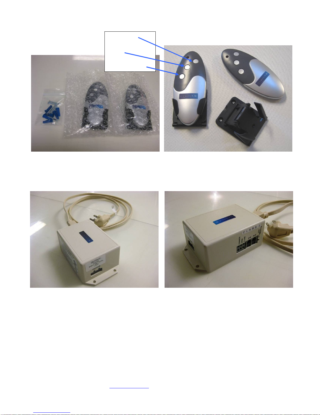
2) The contents of the white accessories box will of course vary depending on what motor option
and control peripherals you bought.
a. All screens come with a bag of 5, 18-8 stainless steel #12-2” screws to mount the DIN
bar to the wall or ceiling. These screws require a 3/16” pilot screw drill and a #3 drive
bit.
b. Gen4 RF-only controlled screens (option “E” or “U”) come with two RF-remotes, their two
wall/ table brackets, and 6 pair of #4-1” screws and #6 conical wall anchors. If you have
rigid walls, then you can just mount the remote bracket with the screws if you choose.
They may require a 1/16” pilot hole into hard woods like oak, or 3/64” pilot hole into soft
woods, or even no pilot hole at all if the wood is soft enough. They use a #1 drive head.
If you have hollow walls, then the plastic anchors can be used. They require a 3/16”
pilot hole and can be tapped flush into the wall with a hammer. Obviously, the remotes
weigh very little and it’s overkill to use three load-bearing screws per side. Some folks
use Velcro or double-sided tape. Some don’t mount them to the wall at all. Since they
are non-directional, however, wall mounting makes them as easy to use as a light
switch.
Copyright ©2009, Seymour Products LLC, www.seymourav.com, All rights reserved.
c. If you selected the Gen4 4-wire controlled screen (option “F” or “V”), you may have also
added the Gen4 motor control box. If so, this would also be in the accessories box and
would look like the pictures below, unless you got the 230v that omits the 72” white
power cord.
d. All screens also come with some swag or other gifts (e.g. popcorn) in the accessories
box, because we don’t take for granted the opportunity you’ve given us to exceed your
expectations.
Screen up
Stop
Screen down

Copyright ©2009, Seymour Products LLC, www.seymourav.com, All rights reserved.
3) Slide off the screen case protective velvet bag and set aside.
4) Leave the internal, foam wrap on the screen. We taped it so that you can install the screen with
this wrap on and avoid scratching up the case.
5) PLEASE, save your box and packaging supplies. It’s quite costly to ship out replacement
packaging supplies, because while we can fold the boxes up fairly compactly, they are
dimensionally expensive to ship and complicated with regard to placing the packaging
components correctly.
Electric Screen Installation Instructions
Wall Mount
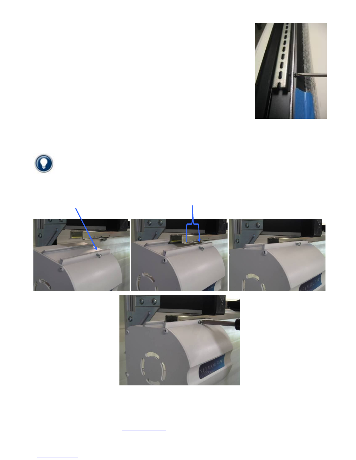
4) Look on the back side (since it's a wall mount) and you'll see the
metal DIN rail that will mount to the wall. There are two screws fixing
this into the case for shipment. Loosen these two screws to get the rail
out and note how the French cleat design works. You'll be doing the
opposite on the wall.
5) Locate the bag in the white remote box that has the five stainless
steel truss head screws. Grab a level and mount the DIN rail to your
wall using these screws. If you have a very curvy wall, you can space
out a screw or two with washers or shims. You don't want the DIN rail to be curvy, or else the case
won't engage all the way. Make sure at least three screws are securely mounted into a stud.
6) After the DIN rail is up and level, you and your buddy can pick up the screen. Put your finger on the
closest screw to your end so you can approximate the ~1.5" from the end of the DIN rail that the screw
will engage.
7) Approach the DIN rail with the screen case tilted up at a 30-40 degree angle. Your goal is to hook
the extruded bevel into the top of the DIN rail fully. Once you have got that, you can then rotate the
screen down to its resting spot and the DIN rail should then nest inside that slot, just like it was when it
was shipped to you.

Copyright ©2009, Seymour Products LLC, www.seymourav.com, All rights reserved.
8) You can slide the case on the wall to make sure it's where you want.
9) When it's where you want, there are six screws along the bottom of the case. Tighten these so that
the screen will be securely affixed to the DIN rail.
10) Remove the foam wrap off the case.
11) Note there are several pieces of tape and things that keep the
materials where they should be. First, undo the blue velcro straps
you see on each end. These keep the weight bar happy during
shipment, but must be taken off prior to operating the screen.
12) We tie small black strings in each corner that attach the black
backing layer to the weight bar. This ensures that it will retract
properly from the case. Leave these alone, but it’s a good idea to
reach up and pull down the black backing material in the middle
and make sure it's down and will drop freely. You really want to
make sure it's free to drop before you hit the remote. Getting that layer backwards-wound in the case
is a disaster.
13) Don't worry about the tape on the weight bar. You can get that off after you drop the screen. After
you are sure the black backing is free to drop and all other blue bits are off the screen, plug it in and hit
the down button.
14) Check that the lower limit is ok, remove any remaining blue bits.
15) Check the vertical turnbuckles at the weight bar. Make sure they’re not bound up, either with the
cables twisted at the top of the eyelet, or the threads on the bar. If they are, the bar will be artificially
lifted, resulting in waves. Straighten any twisted cable and wiggle the bar to get it off the threads.
16) Check how the vertical cable and turnbuckles retract up into the screen case. You want them to
easily retract up into the case, without getting caught or hung up on either the front side of the case
near the foam strip, or the back side. If you hear any “clunk” sound, or see the motor bog down before
the screen is all the way up, check that these turnbuckles aren’t getting hung up. The fix is to just grab
the metal portion of the weight bar and rotate a few degrees to better align the turnbuckles into the slot.
17) Dial in your projector, go pop that popcorn, and enjoy!
Ceiling Mount
4) Look on the top side (since it's a ceiling mount) and you'll see the metal DIN rail that will mount to the
wall. The front side of the rail is painted to match your case color. There are two screws fixing this into
Copyright ©2009, Seymour Products LLC, www.seymourav.com, All rights reserved.
the case for shipment. Loosen these two screws to get the rail out and note
how the French cleat design works. You'll be doing the opposite on the
ceiling.
5) Locate the bag in the white remote box that has the five stainless steel
truss-head screws. These screws are intended for most standard ceilings
and wood joists. If you have a nonstandard ceiling type, just make sure that
you use appropriate load-bearing screws mounted into load-bearing
members. The DIN bar can accommodate up to #12 screws. The screen
weighs approximately 50-70 pounds, but you must make sure the mounting
technique you’re using is rated for at least 4 times that weight.
Mark where your DIN rail bar is to be mounted to the ceiling joists. Install
using the included SS screws (or your substitute). At least three screws,
securely mounted into your joists, are required. If you have a very curvy ceiling, you can space out a
screw or two with washers. You don't want the DIN rail to be curvy, or else the case won't engage all
the way.
Giving the DIN rail a little squeeze with pliers will narrow the distance the case needs to engage
onto, making it an easier mount.
6) After the DIN rail is up and level, you and your buddy can pick up the screen. Put your finger on the
closest screw to your end so you can approximate the ~1.5" from the end of the DIN rail that the screw
will engage.
7) Approach the DIN rail with the screen case tilted down at a 30-40 degree angle. Your goal is to hook
the extruded bevel into the back of the DIN rail fully. Once you have got that, you can then rotate the
screen up to its resting spot and the DIN rail will nest inside that slot, just like it was when it was
shipped to you. You must tighten at least one screw on each end so the case holds onto the rail.

Copyright ©2009, Seymour Products LLC, www.seymourav.com, All rights reserved.
NOTE: There have been installations where the ceiling was curvy enough and the DIN bar was
mounted flush enough so that it also had too much curve in it to mate to the case easily. If you
encounter this issue and have the space, you can alternatively engage the case onto the bar on one or
two screws on the end, and simply slide the case along, extending but not tightening the case screws
as you slide it along.
If you find the case won’t engage over the DIN rail on one side, there must be some mounting
forces that are spreading it wider (curve, etc.) Take the end that isn’t engaging and give it a squeeze
with pliers, narrowing it enough to engage fully into the case.
8) If you loosen the screws just enough so they don’t bite into the rail, but are protruding enough to hold
the case on the rail, you can slide the case along the ceiling to make sure it's where you want. Feel
free to bump the case into exactitude (that’s actually a word).
9) When it's where you want, there are six screws along the top of
the case. Tighten these so that the screen will be securely affixed
to the DIN rail. There are arrow marks on the foam wrap showing
you where they are.
10) Remove the foam wrap off the case.
11) Note there are several pieces of tape and things that keep the
materials where they should be. First, undo the blue velcro straps
you see on each end. These keep the weight bar happy during
shipment, but must be taken off prior to operating the screen.
12) We tie small black strings in each corner that attach the black
backing layer to the weight bar. This ensures that it will retract
properly from the case. Leave these alone, but it’s a good idea to
reach up and pull down the black backing material in the middle
and make sure it's down and will drop freely. You really want to
make sure it's free to drop before you hit the remote. Getting that layer backwards-wound in the case
is a disaster.
13) Don't worry about the tape on the weight bar. You can get that off after you drop the screen. After
you are sure the black backing is free to drop and all other blue bits are off the screen, plug it in and hit
the down button.
14) Check that the lower limit is ok, remove any remaining blue bits.
15) Check the vertical turnbuckles at the weight bar. Make sure they’re not bound up, either with the
cables twisted at the top of the eyelet, or the threads on the bar. If they are, the bar will be artificially
lifted, resulting in waves. Straighten any twisted cable and wiggle the bar to get it off the threads.
16) Check how the vertical cable and turnbuckles retract up into the screen case. You want them to
easily retract up into the case, without getting caught or hung up on either the front side of the case
near the foam strip, or the back side. If you hear any “clunk” sound, or see the motor bog down before
the screen is all the way up, check that these turnbuckles aren’t getting hung up. The fix is to just grab
the metal portion of the weight bar and rotate a few degrees to better align the turnbuckles into the slot.
17) Dial in your projector, go pop that popcorn, and enjoy!
Copyright ©2009, Seymour Products LLC, www.seymourav.com, All rights reserved.
Gen4 4-wire and Somfy®Motor Control Options
If you opted for the 4-wire or Somfy motor option, then there are a million ways to control your screen.
While it’s certainly possible with either option to be able to drop your screen with your iPod from the
office, the more common approaches will be covered here.
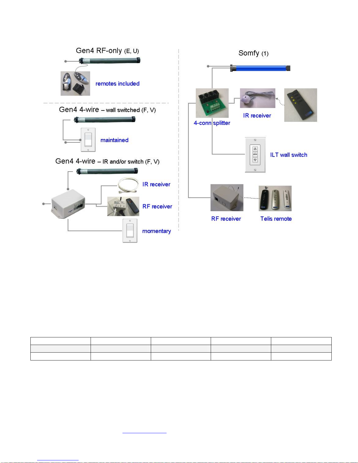
Gen4 4-wire wall switched ONLY
With this motor option, we will have left the ends of the ~72”-long 4-wire motor stripped. You can wire
this directly, or splice it to a maintained wall switch or external relays. The motors are 220w, so make
sure your relays are rated for this power draw. When the power is applied to the up or down power
wire (see the chart below), the motor will continue travelling until it reaches its mechanically-set limits.
Typical screen motoring times are about 15-20 seconds depending on size and aspect ratio.
Ground Neutral Screen Up Screen Down
115v Green White Red Black
230v Yellow/Green Blue Brown Black
Gen4 4-wire motor control box options
With the control box, many more control options open up. In this case, we would have wired the ~72”
long 4-wire cable with the special plug already attached. This makes installation as simple as:
a) Plugging in the included power cable to the control box (you can substitute with a different IEC
power cable if you like, or the 230v folks will need to get one suitable for their own bizarre outlet
shape)

Copyright ©2009, Seymour Products LLC, www.seymourav.com, All rights reserved.
b) Plugging the screen motor’s 4-wire connector into the control box, and
c) Plugging in or wiring the control peripheral of your choosing.
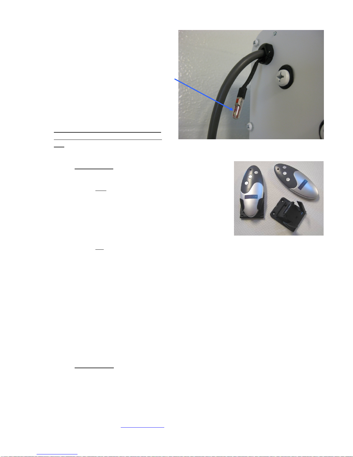
Gen4 4-wire connection
If you ordered the motor control box with your screen, we will have already attached the control box
connector to it. If you didn’t, here are some pics to show how to install the connector. Because our
direction convention is different than our control products vendor uses, we reverse the up and down
wires into the connector. In other words, we put the red wire in the black terminal, and vice versa. If
you buy the connector separately, it will come with a little plastic tool when you squeeze it with pliers, it
will force the terminal spring open. If you don’t have this tool, simply poke a small bladed screwdriver
to do the same thing.
Gen4 4-wire IR control
For IR control, simply plug the IR receiver you chose into
the “eye” port of the control box using the phone cord. If
you also purchased the IR remote, the button layout is the
same as our RF remote. We don’t commonly sell these, so
haven’t sprung for custom labels, so the top button (ignore
that it’s confusingly labeled “open”) is screen up, the red
button is obviously stop, and the bottom button (also ignore
Screen up
Stop
Screen down

Copyright ©2009, Seymour Products LLC, www.seymourav.com, All rights reserved.
that it’s confusingly labeled “close”) is screen down. Most people simply download the IR codes on our
screens page http://www.seymourav.com/screensretractable.asp
The IR receivers that state a length (e.g. 24”, 72”) come with the phone plug on the end of the cord.
The more permanently mounted “wall mount” and “J-box” (for installation to look like a wall switch) don’t
come with cords. We have phone cords available in any length for your needs. They’re available on
the store page if you need.
Gen4 4-wire RF control
Some folks like the no-pointing reliability of RF control,
but they still wanted more control options and flexibility
that the motor control box brings. For these applications,
we have an RF module that simply plugs into the “eye”
port of the control box, as well as an RF remote.
Gen4 4-wire motor control box wall-switched, or relay controlled
For dry contact switching, there are three
terminals on the side of the motor control
box. Common use for these include:
1. Wiring a wall switch. In this case,
you’ll need a momentary wall
switch, the kind that springs back to
center. The motor control box only
wants to see a brief closing of
contacts common/open for screen
up, and common/close for screen
down.
2. Wiring in relay triggering from a
universal remote system. If you’re
using relays, program them for 0.5
seconds or less. The control box
expects momentary closure. If after actuation it sees the circuit closed still (or again), it will stop
the actuation prematurely.
3. Hotwire controlling the screen. Simply connect a
small gauge wire into the “common” terminal, and
then touch the other end of the wire to either the
“open” terminal (screen up) or the “closed”
terminal (screen down).
The wiring you need can be phone or signal cable,
because there is no current or power travelling through
the circuit. The box is simply looking for “short” or
“open”. Simply poke a narrow standard electronics-type
screwdriver into the upper cavity and press down. This
will force the terminal spring open, allowing you to insert
the wire.
Copyright ©2009, Seymour Products LLC, www.seymourav.com, All rights reserved.
Gen4 nonstandard options
Less common modules we can special order include Z-wave, RS-232, USB to DE9 serial, and serial to
Ethernet adapters. Just in case you NEED to drop the screen using your iPod from work.
Somfy control
The Somfy motor option comes with a ~24” control cable with a little phone handset plug on the end.
These smart motors can be controlled many different ways.
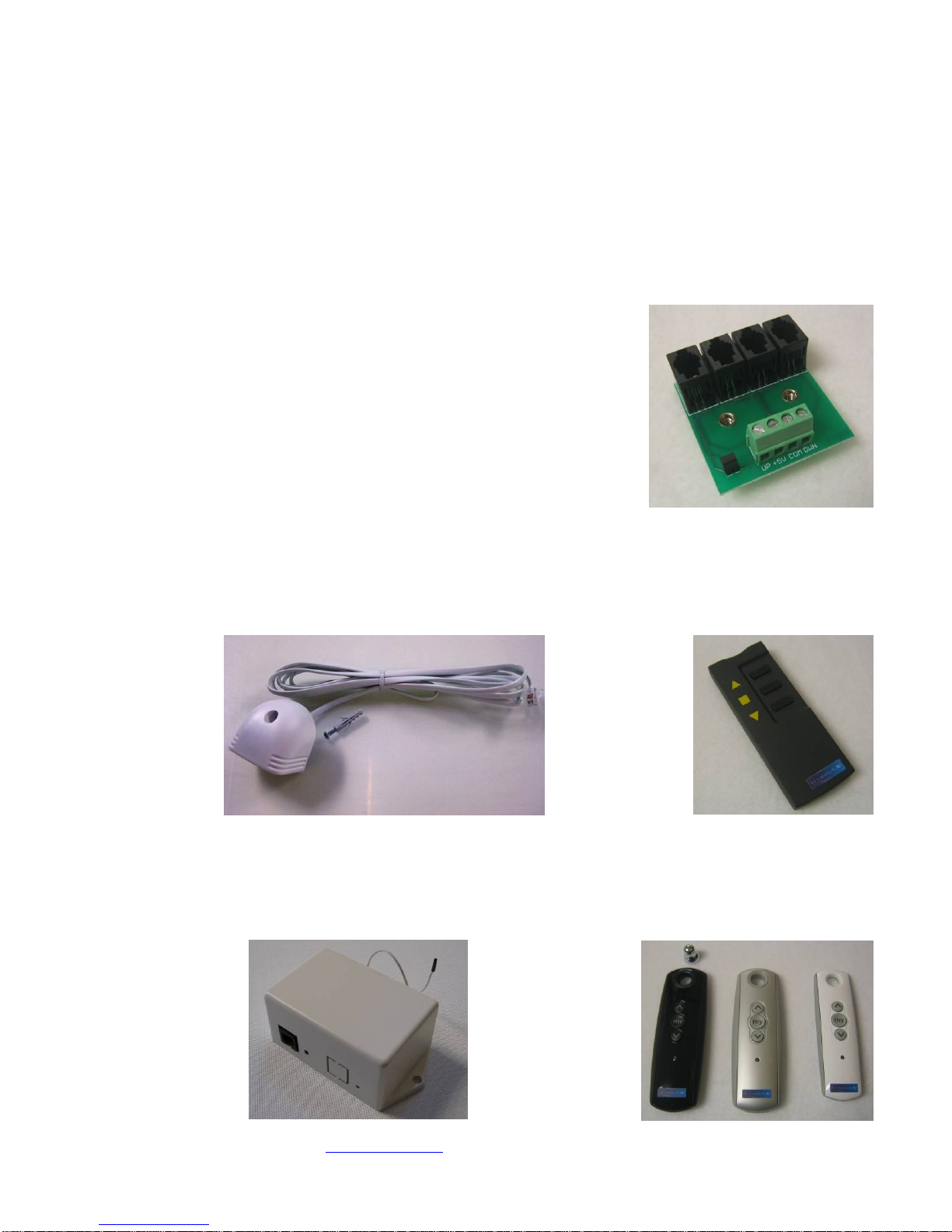
Somfy 4-connector splitter
A great little piece of hardware is this 4-connector splitter. You can
easily plug in the motor control cable, and then branch off to other
devices such as an IR receiver, RF receiver, or directly wire dry
contacts. As outlined above in the Gen4 motor control box instructions,
you can directly wire a momentary wall switch into these terminals, or
you can program relay control for 0.5 seconds or less closure. We will
have already programmed the direction option into the motor, so “up” is
up and “down” is down.
Somfy IR control
Simply plug the IR receiver onto either the motor control cable, or into a jack in the splitter. Somfy IR
codes are easily found in your universal remote library, typically in the “appliance” section, since they’re
typically associated with shade controls. If you need the IR remote, we have those as well.
Somfy RF control
For RF control, either plug the receiver directly onto the motor control cable, or into a jack in the splitter.
You’ll need a RF remote, which we have in three colors. You’ll also likely need a control cable, which
we make in white or black by the foot.
Copyright ©2009, Seymour Products LLC, www.seymourav.com, All rights reserved.
Gen4 Standard RF Motor Limits Setting (RF motors with LED dongle)
Your RF remote has a couple programming
functions built in, so unless you’re intending on
tweaking the configuration of the screen, please
do NOT continuously hold down button combos.
If you press and hold both the up and
down buttons down for a few seconds, the
motor will change direction. If you ever
find that up is down and down is up and
you’re sober, then you’ll want to put that
back the way it’s supposed to be. The
motor confirms that it understood your
command with a little bump and flashing
of the LED.
If you are intending to adjust the lower
limits, retract the screen all the way up
first. If you press and hold both the stop and down buttons for a few seconds, you’ve entered
limits programming. Depending on if this was accidental or on purpose, here is what’s going on
while the LED slowly blinks.
oUpper Limits When it first starts blinking, it is in the
upper limits setting mode. Is the screen fully retracted
up into the case when you entered this mode?
Yes: Then you won’t need to fix the upper
limits. We very carefully program that here.
Press Stop. This will exit upper limits
mode and retain the upper position we
programmed. The blinking will change
for a couple blinkings to confirm. You
can proceed to the lower limits part
below.
No: Crap. You’ll need to fix the upper limits setting.
Press Down. The motor is first in a continuous travel setting. Down is
the safer direction.
Press Stop. Now you’ve entered the precise or small-bump setting for
the motor. The motor will now only travel following your up/down button
commands.
Bump up/down. Long presses will travel the motor longer, and little
quick presses will bump the motor. The goal for the upper limits setting is
to get it up into the case as much as possible but making sure that both
ends of the weight bar can still wobble a bit inside, indicating that they’re
not jammed inside. One end may be higher than the other, depending on
how the cables coil up, so target the higher end and carefully bump it into
a hidden, but free hanging position.
Press Stop. This will exit upper limits mode you just programmed. The
blinking will change for a couple blinks to confirm. You can proceed to
the lower limits part below.
oLower Limits Next, always following the upper limits mode, is the lower limits setting.
Since you just exited the upper limits, I now know your screen is in the upper position
and what you need to do next
Press Down. The motor is first in a continuous travel setting, so carefully watch
it drop until you’re a few inches away from your targeted setting. Watch the
tension cables to make sure you don’t go past their limits. If you do, you’ll start
winding the cables while dropping the screen and the bar will start to fold up the
Copyright ©2009, Seymour Products LLC, www.seymourav.com, All rights reserved.
screen. The smarter approach would be to stop the motor before reaching your
target.
Press Stop. Now you’ve entered the precise or small-bump setting for the
motor. The motor will now only travel following your button commands.
Bump up/down. Long presses will travel the motor longer, and little quick
presses will bump the motor. Hit your lower limits target, while making sure the
cables are ok per the above mention.
Press Stop. This will exit lower limits mode you just programmed. The blinking
will change for a couple blinks to confirm and the motor will do a little bump after
a few seconds of contemplating its new position in life.
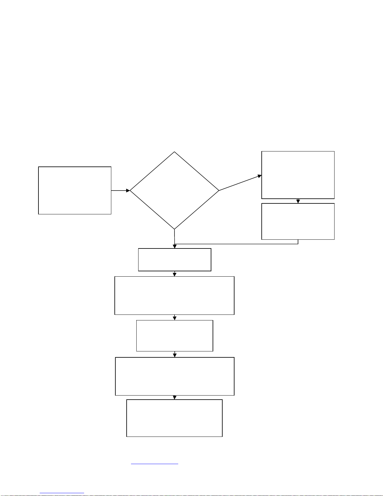
Gen4 Limits Setting Flowchart
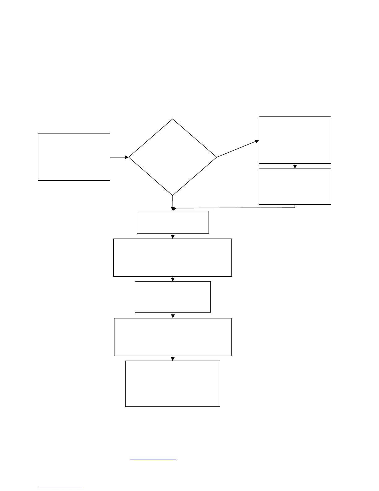
Graphically, here is how the standard RF motor’s limits adjustment algorithm works. Again, I
recommend prior to entering this mode to raise the screen all the way up first, since it’s very unlikely
you want to adjust the upper limits:
Hold <stop> and
<down> for a few
seconds. The LED
starts blinking
repeatedly.
Is the motor
in the
intended
upper limits?
Press <down> and
then <stop> to exit
continuous mode
and enter bump
mode.
NO
Press <up> or
<down> to adjust
motor to the precise
upper limits
.
Press <stop> to exit
upper limits mode.
YES
Now the motor is in lower limits
setting mode. Press <down> and
wait until motor is a few inches
away from the targeted lower limit.
Press <stop> to exit
continuous mode and
enter bump mode.
Press <up> or <down> to adjust
motor to the precise lower limits.
Check that you aren’t exceeding
the cables’ capabilities.
Press <stop> to exit lower
limits mode. The LED will
blink in confirmation and do
a little jog.
Copyright ©2009, Seymour Products LLC, www.seymourav.com, All rights reserved.
Gen3 Standard RF Motor Limits Setting (RF motors without LED dongle)
Your RF remote has a couple programming functions built in, so
unless you’re intending on tweaking the configuration of the screen,
please do NOT continuously hold down button combos.
If you press and hold both the up and down buttons down for
a few seconds, the motor will change direction. If you ever
find that up is down and down is up and you’re sober, then
you’ll want to put that back the way it’s supposed to be. The
motor confirms that it understood your command with a little
bump.
If you are intending to adjust the lower limits, retract the
screen all the way up first. If you press and hold both the stop
and down buttons for a few seconds, you’ve entered limits programming. Depending on if this
was accidental or on purpose, here is what’s going on while the continuous beeping sound
drives you insane.
oUpper Limits When it first starts beeping, it is in the upper limits setting mode. Is the
screen fully retracted up into the case when you entered this mode?
Yes: Then you won’t need to fix the upper limits. We very carefully program that
here.
Press Stop. This will exit upper limits mode and retain the upper position
we programmed. The beeping will change for a couple beeps to confirm.
You can proceed to the lower limits part below.
No: Crap. You’ll need to fix the upper limits setting.
Press Down. The motor is first in a continuous travel setting. Down is
the safer direction.
Press Stop. Now you’ve entered the precise or small-bump setting for
the motor. The motor will now only travel following your up/down button
commands.
Bump up/down. Long presses will travel the motor longer, and little
quick presses will bump the motor. The goal for the upper limits setting is
to get it up into the case as much as possible but making sure that both
ends of the weight bar can still wobble a bit inside, indicating that they’re
not jammed inside. One end may be higher than the other, depending on
how the cables coil up, so target the higher end and carefully bump it into
a hidden, but free hanging position.
Press Stop. This will exit upper limits mode you just programmed. The
beeping will change for a couple beeps to confirm. You can proceed to
the lower limits part below.
oLower Limits Next, always following the upper limits mode, is the lower limits setting.
Since you just exited the upper limits, I now know your screen is in the upper position
and what you need to do next
Press Down. The motor is first in a continuous travel setting, so carefully watch
it drop until you’re a few inches away from your targeted setting. Watch the
tension cables to make sure you don’t go past their limits. If you do, you’ll start
winding the cables while dropping the screen and the bar will start to fold up the
screen. The smarter approach would be to stop the motor before reaching your
target.
Press Stop. Now you’ve entered the precise or small-bump setting for the
motor. The motor will now only travel following your button commands.
Copyright ©2009, Seymour Products LLC, www.seymourav.com, All rights reserved.
Bump up/down. Long presses will travel the motor longer, and little quick
presses will bump the motor. Hit your lower limits target, while making sure the
cables are ok per the above mention.
Press Stop. This will exit lower limits mode you just programmed. The beeping
will change for a couple beeps to confirm and the motor will do a little bump.
Gen3 Limits Setting Flowchart
Graphically, here is how the standard RF motor’s limits adjustment algorithm works. Again, I
recommend prior to entering this mode to raise the screen all the way up first, since it’s very unlikely
you want to adjust the upper limits:
Hold <stop> and
<down> for a few
seconds. The motor
starts beeping
repeatedly.
Is the motor
in the
intended
upper limits?
Press <down> and
then <stop> to exit
continuous mode
and enter bump
mode.
NO
Press <up> or
<down> to adjust
motor to the precise
upper limits
.
Press <stop> to exit
upper limits mode.
YES
Now the motor is in lower limits
setting mode. Press <down> and
wait until motor is a few inches
away from the targeted lower limit.
Press <stop> to exit
continuous mode and
enter bump mode.
Press <up> or <down> to adjust
motor to the precise lower limits.
Check that you aren’t exceeding
the cables’ capabilities.
Press <stop> to exit lower
limits mode. The motor will
beep in confirmation and do
a little jog. The incessant
beeping sounds cease.

Copyright ©2009, Seymour Products LLC, www.seymourav.com, All rights reserved.
Gen4 RF remote replacement
The Gen4 motors were designed with the LED
dongle to not only give you yet another light to blink
in your home theater, but to give you access to a
programming button. This button will assign a RF
remote to the motor. If you accidentally pressed this
button, just follow through the remote assignment
process.
1) Press the little red button on the screen’s
LED dongle. This will cause the LED to start
blinking; telling you the motor is looking for a
partner.
2) Press stop on the remote. This will conclude
the courtship and partnership will follow.
3) Being legal in some states, if you’re joining
another remote to the happy couple, just repeat steps 1 and 2, and you’ll have two remotes with
the power to constantly tell your screen what to do.
Troubleshooting
No one likes it, but it happens: here are some possible issues and fixes. If we didn’t cover your issue,
you may be more unique than you’ve been told, so you’ll need to contact us for assistance.
Waves
The Center Stage screen uses a woven material, which for acoustical transparency and fineness of
video resolution is an advantage. The disadvantage is that the material doesn’t naturally stretch like a
piece of plastic wrap, so balancing the tension forces across the screen is critical to not having stresses
build up and cause waves.
The new Center Stage XD™has features built into the weave to eliminate waves in almost every case,
so if you find yourself struggling too much, consider using our generous upgrade policy and get the XD
material.
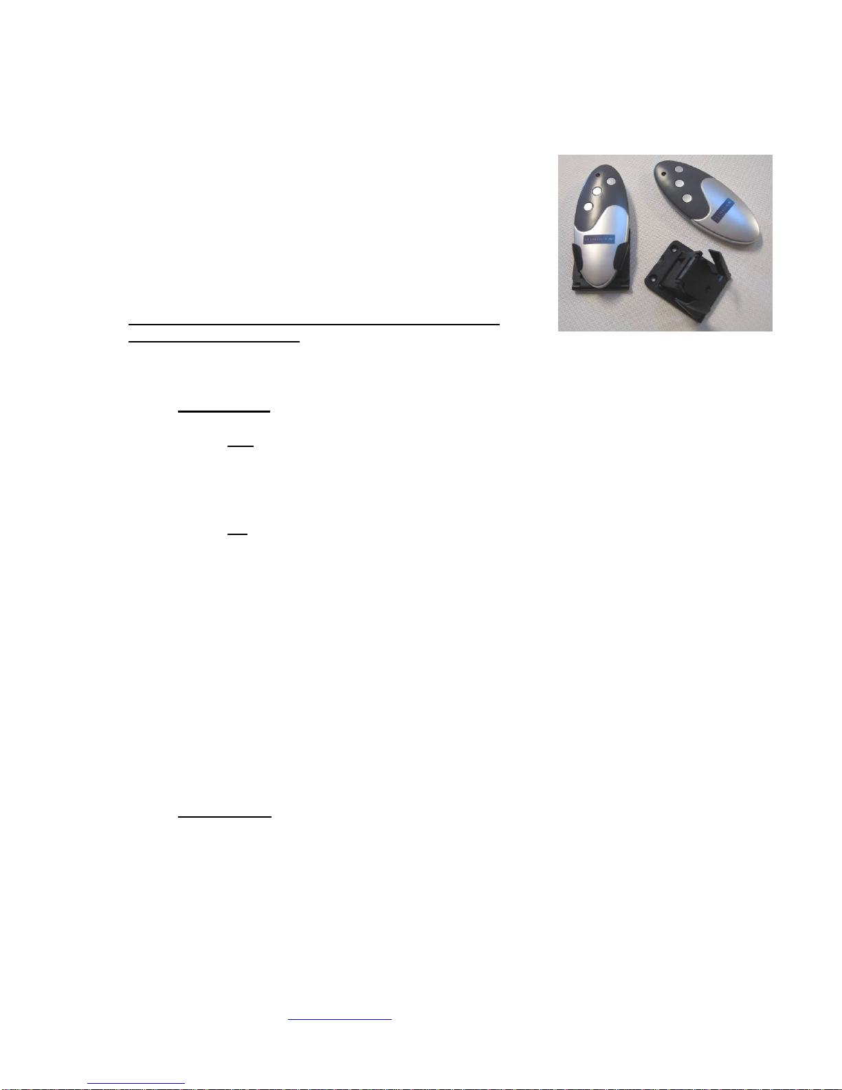
To adjust the tension, there are two turnbuckles on each side of
the screen. The horizontal ones (hereafter called “horizontal”)
feature a standard thread on the rod joining the black plastic
piece attached to the screen. Just focus your eyes on this half
of the turnbuckle, so when we say “tighten,” you think “righty-
tighty, lefty-loosey.” The other half with the screw is reverse
thread and will mess with your mind.
The similar, vertical turnbuckle features its standard thread on
the eyelet joining the cable, with the little nut. We put a dollop of
thread adhesive on this one to keep it from drifting. If you need
to adjust this one, it’s a bit tricky and best with three hands and sets of needlenose pliers. First, pop out
the little plastic endcap on the weight bar so you can grab the in-bar eyelet. Then, grab the eyelet at
the cable loop so it doesn’t twist. Then, with your third hand and pliers, break the nut out of the way.
Finally, the turnbuckle barrel can be grabbed and adjusted as necessary.

Copyright ©2009, Seymour Products LLC, www.seymourav.com, All rights reserved.
If you have vertical wave patterns along the
sides, then your vertical turnbuckles have too little
tension and need to be tightened. Another clue is
the bottom black tabs won’t be grabbed much at
all and will be hanging too loosely.
If you have horizontal wave patterns along the
sides, then your vertical turnbuckles are too tight
and they are lifting the bar. Loosen them up, and
you’ll find the ideal tension is where the bottom
black tabs are snug to the cable but still easily
slid up or down with your finger.
If you have “V” shaped wave patterns in the lower
corners and/or fingering along the bottom, then
your horizontal turnbuckles are too loose and
need to be tightened. A couple signs that you’ve
tightened them too much will be the opposite
wave patterns (see below), or a slight separation
of the screen material from the border velvet.
This joint is very strong, but don’t torque it to
where you see visible strain or distortion of the
screen shape.
If you have the opposite pattern in the lower
corners, then your horizontal turnbuckles are too
tight and need to be loosened a bit. Generally,
you want these tight to provide nice corner
tension, but if you overdo it, not only will these
patterns develop, but a visible gap will open
between the screen and border material at the
bottom corners. While the joint is strong, don’t
distort the screen geometry too much.
After you make the desired adjustments, you could put a little dollop of a clear glue on the threads to
keep it from drifting over time, although drift is relatively minor depending on your environmental
changes in temperature and humidity.
“Ca-chunck” clanking sound when bar goes into case
The vertical turnbuckles are likely catching on the front or back of the case. Simply rotate the weight
bar until they cleanly enter the slot.

Copyright ©2009, Seymour Products LLC, www.seymourav.com, All rights reserved.
Motor bogs down in the upper position before stopping
Your upper limits are set too high. The bar can’t be retracted too far into the case before it will burden
the motor. You want your upper limits to engage before this happens. Find that upper limit setting
where the bar visibly retracts into the case as much as possible, but still can be moved a little with your
fingers. It needs to “float” up there, not being packed tight and bogging down the motor.
RF remote doesn’t work
The battery lasts about three years. Simply unscrew the case and replace the battery if necessary. If
the battery is known to be good and the remote still doesn’t work, if you have a Gen4 motor, simply re-
assign it as shown above using the button on the LED dongle.
Table of contents
Popular Projection Screen manuals by other brands


Da-Lite
Da-Lite Cosmopolitan Electrol Instruction book

Akia Screens
Akia Screens Fixed Frame Screen Series user guide

Welltime
Welltime 73114119-1026806 Installation instruction

TEREN
TEREN THD quick start guide

AVstumpfl
AVstumpfl MONOBLOX 32 Instruction

Draper
Draper Targa Installation & operating instructions


