SF AllVac Commercial Owner's manual

RRGA-SVX01A-EN
Model Numbers: RRGA123E0A0, RRGA123B0A0, RRGA123C0A0,
RRGA123F0A0, RRGA123G0A0, RRGA323E0A0, RRGA323B0A0,
RRGA323C0A0, RRGA323F0A0, RRGA323G0A0
Installation
Operation
Maintenance
AllVac Commercial
High and Low Pressure Commercial Refrigerant
Recovery System

2RRGA-SVX01A-EN
General Information. . . . . . . . . . . . . . . . . . . . . . . . . . . . . . . . . . . . . . . . . 3
Warnings and Cautions . . . . . . . . . . . . . . . . . . . . . . . . . . . . . . . 3
Model Number Description . . . . . . . . . . . . . . . . . . . . . . . . . . . . . 3
Literature History . . . . . . . . . . . . . . . . . . . . . . . . . . . . . . . . . . . . 3
Specifications . . . . . . . . . . . . . . . . . . . . . . . . . . . . . . . . . . . . . . . 4
Product Description . . . . . . . . . . . . . . . . . . . . . . . . . . . . . . . . . . 5
Figure 1 — AllVac Connections . . . . . . . . . . . . . . . . . . . . . . . . . 6
Figure 2 — AllVac Schematic. . . . . . . . . . . . . . . . . . . . . . . . . . . 8
Operating Procedures . . . . . . . . . . . . . . . . . . . . . . . . . . . . . . . . . . . . . . . 9
Removing Residual Refrigerant . . . . . . . . . . . . . . . . . . . . . . . . 14
Calibration . . . . . . . . . . . . . . . . . . . . . . . . . . . . . . . . . . . . . . . . . . . . . . . 19
Calibration Procedure. . . . . . . . . . . . . . . . . . . . . . . . . . . . . . . . 19
Changing Compressor Fluid. . . . . . . . . . . . . . . . . . . . . . . . . . . 20
Figure 3 — 230/460, 1 Phase Model . . . . . . . . . . . . . . . . . . . . 21
Figure 4 — 230, 1 Phase Model. . . . . . . . . . . . . . . . . . . . . . . . 22
Figure 5 — 230/460, 3 Phase Model . . . . . . . . . . . . . . . . . . . . 23
Display Sequence . . . . . . . . . . . . . . . . . . . . . . . . . . . . . . . . . . 24
Electrical . . . . . . . . . . . . . . . . . . . . . . . . . . . . . . . . . . . . . . . . . . . . . . . . . 26
Electrical Parts List . . . . . . . . . . . . . . . . . . . . . . . . . . . . . . . . . . 26
Figure 6 — Electrical Parts Breakdown . . . . . . . . . . . . . . . . . . 27
Replacement Parts List . . . . . . . . . . . . . . . . . . . . . . . . . . . . . . 28
Figure 7 — Replacement Parts Diagram . . . . . . . . . . . . . . . . . 29
Figure 8 — 230/460, 1 Phase Model, Electrical Controls. . . . . 30
Figure 9 — 230/460, 3 Phase Model, Electrical Controls. . . . . 31
Figure 10 — 230, 1 Phase Model, Electrical Controls . . . . . . . 32
Troubleshooting. . . . . . . . . . . . . . . . . . . . . . . . . . . . . . . . . . . . . . . . . . . 33
Table of Contents
RRGA-SVX01A-EN 3
General
Information
Warnings and Cautions
Warnings and Cautions appear at appropriate locations throughout this
manual. Read these carefully.
Indicates a potentially hazardous
situation which, if not avoided,
could result in death or serious
injury.
Indicates a potentially hazardous
situation which, if not avoided,
may result in minor or moderate
injury. It may be used to alert
against unsafe practices and
where property-damage-only
accidents could occur.
WARNING
!CAUTION
!
Model number description
Refrigerant Recovery
Digits 1, 2 - Product Description
RR = Refrigerant Recovery
Digit 3 - Model Identifier
A = MicroVac
B = HandiVac
C = MityVac
D = EVAC Commercial
E = EVAC Industrial
F = LoVac
G = AllVac
Digit 4 - Development Sequence
A = First Development
Digit 5 - Condenser Type
1 = Air Cooled
2 = Water Cooled
3 = Air/Water Cooled
Digit 6 - Control Type
1 = Electromechanical
2 = Microprocessor
Digit 7 - Connection Type
1 = 1/4” flare
2 = 1/2” flare
3 = 3/4” flare
4 = 1.25” pipe thread fitting w/ball valve
5 = Quick Connects on unit and hoses
Digit 8 - Unit Voltage (voltage/hz/phase)
A = 115/60/1, 110/50/1
B = 230/60/1, 220/50/1
C = 460/60/3, 415/50/3
D = 575/60/3, 220/50/3
E = 230/60/3, 220/50/3
F = 575/60/3
G = 230-460/60/1, 220-415/50/1
H = 460-575/60/3, 415-550/50/3
Digit 9 - Safety Features
0 = Open
1 = Float Cable Connection
2 = Low Pressure Shut-Off
3 = Float cable connection, LP shut-off
Digits 10, 11 - Design Sequence
A0 = First Design Sequence
Literature History
RRGA-SVX-01A (April 2001)
Original issue of manual. Describes the Installa-
tion, Operation and Maintenance procedures for
this unit.
RRGA111A0A0
1234567891011
4RRGA-SVX01A-EN
General
Information
Electrical Power Requirements
Recovery Main Components & Controls:
• 115VAC, 50/60 Hz, 1-Phase, 20-Amperes Min. CKT 15.0 Amp, Max
Fuse 20 Amps
Models RRGA123G0A0 & RRGA323G0A0:
•Compressor 230/460 VAC, 50/60Hz, 1 Phase Min. CKT 20.0 Amp,
Max Fuse 30 Amps.
Models RRGA123B0A0 & RRGA323B0A0:
•Compressor 220/240VAC, 50/60Hz, 1 Phase MIN CKT 20.0 AMP,
Max Fuse 30 Amps.
Models RRGA123E0A0 & RRGA323E0A0:
• Compressor 230 VAC, 50/60Hz, 3 Phase Min. CKT 10.0 Amp, Max-
Fuse 20 Amps.
Models RRGA123C0A0 & RRGA323C0A0:
• Compressor 460 VAC, 50/60Hz, 1 Phase Min. CKT 10.0 Amp, Max
Fuse 15 Amps.
Models RRGA123F0A0 & RRGA323F0A0:
• Compressor 575 VAC, 50/60Hz, 1 Phase Min. CKT 10.0 Amp, Max
Fuse 15 Amps.
Dimensions (approximate)
• 41” high x 24” wide x 27” deep
Weight
• 240-lbs. (340-lbs. shipping)
Notice
The Trane Company urges that all HVAC servicers working on Trane equipment, or any
manufacturer’s products, make every effort to eliminate, if possible, or vigorously reduce the
emission of CFC, HCFC and HFC refrigerants to the atmosphere resulting from installation,
operation, routine maintenance, or major service on this equipment. Always act in a
responsible manner to conserve refrigerants for continued use even when acceptable
alternatives are available. Conservation and emission-reduction can be accomplished by
following recom- mended Trane service and safety procedures published in Trane General
Service Bulletin CTV-SB-81. The information and procedures provided in CTV-SB-81
supersedes those published in this manual. Copies of this bulletin may be obtained by
contacting your local Trane commercial representative.
WARNING!
To avoid injury or death due to inhalation of, or skin exposure to refrigerant, closely follow all
safety procedures described in the Material Safety Data Sheet for the refrigerant and to all
labels on refrigerant containers. Certain procedures common to refrigeration system service
may expose personnel to liquid or vaporous refrigerant.

RRGA-SVX01A-EN 5
General
Information
Product Description
RefTec’s AllVac recovery system provides automated recovery of most low &
high pressure refrigerants and blends.
The unit consists of a 3 or 5-hp compressor with oil separator, disposable
liquid & vapor prefilter driers, high capacity air cooled condenser,
microprocessor control system, and actuated valving system. Unit
connections are 3/4” male flare with isolation valves.
After hoses are connected and purged or evacuated, AllVac starts
automated recovery by letting refrigerant migrate from the A/C system to the
recovery tank. It then draws vapor off the recovery tank, heats it via
compression, and injects it back into the A/C system high side, thus creating
a pressure differential before commencing liquid transfer.
A sensor determines when liquid transfer is complete, and AllVac’s
compressor begins moving vapor, which is first cleansed by a filter drier.
Discharged hot compressed gas passes through an oil separator and the oil
is returned to the compressor. Refrigerant is then condensed by the air-
cooled condenser and sent to the recovery tank.
The AllVac can be programmed to stop transfer at either 0 PSI or at 15” Hg
vacuum for high pressure refrigerant and either 0 PSI or at 29” Hg vacuum
for low pressure refrigerants. Transfer stops when a pressure transducer
indicates the A/C system reaches the programmed pressure. The unit then
confirms the vacuum level by monitoring pressure for two minutes. Should
pressure in the A/C system rise, AllVac energizes again to achieve A/C
system selected level of vacuum.
6RRGA-SVX01A-EN
General
Information
DRIERS
3/4” RECOVERY
CYLINDER PORTS
VAPOR
20-FT
3/4” PORT: 3/4” PORT:
CONDENSER
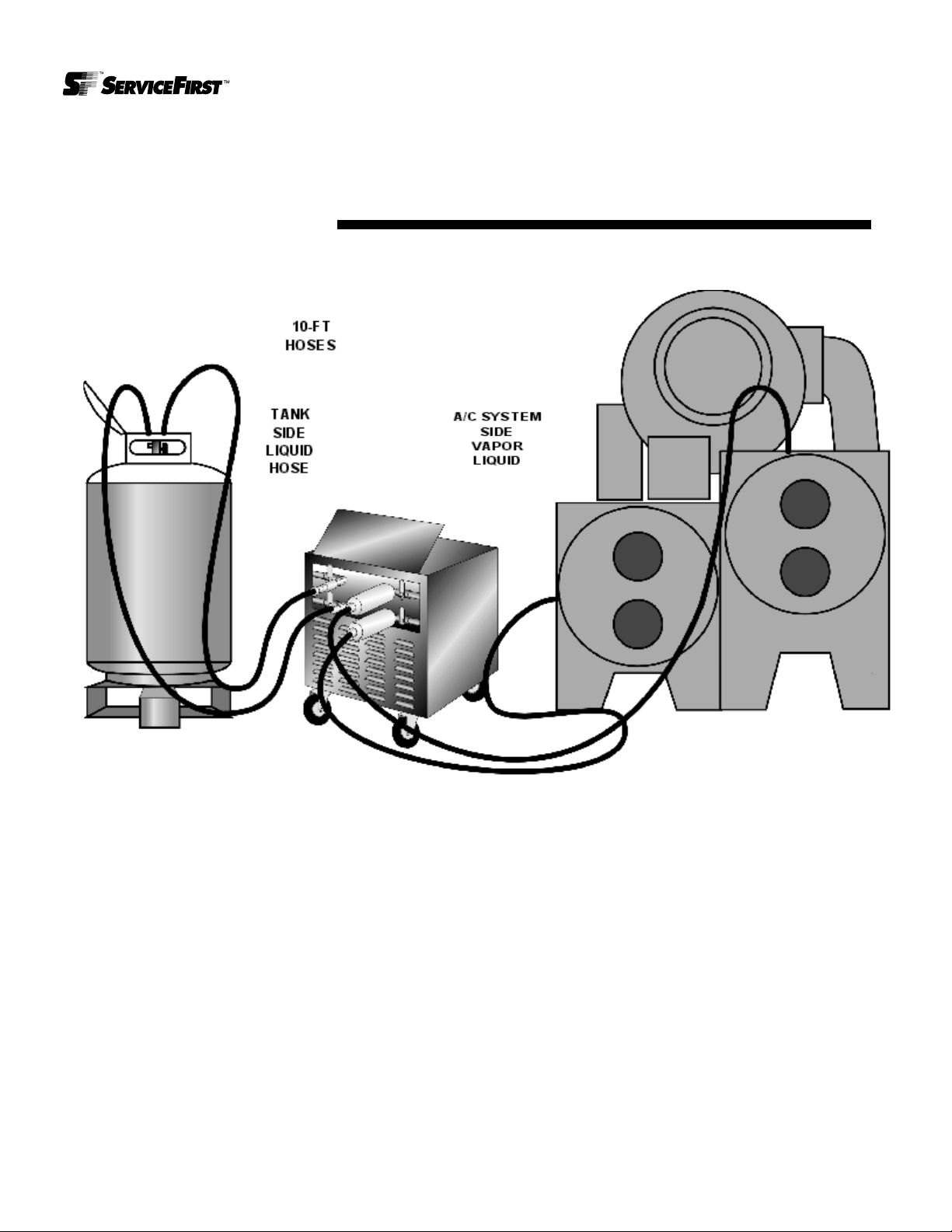
Figure 1. AllVac Connections

RRGA-SVX01A-EN 7
General
Information
Furnished with the AllVac are:
• Two -10-ft. and 20-ft. 3/4” hoses equipped with four 3/4” female flare
fittings with isolation valves
• Two - 3/4”-5/8” flare reducing fittings
• Two - 5/8” -1/2” flare reducing fittings
• Two - 3/4” female flare unions
• 50-ft., 230/460-VAC power cord
• 100-ft., 120-VAC power cord
• Two - 3/4” female flare 0.73-liter disposable in-line filter driers
Please follow the recommended procedures outlined in this manual for
regular changing of compressor fluid. Before every recovery job install
new liquid and vapor drier cores.
Peak Performance:
To get the highest performance from your AllVac unit, we recommend that
you:
1. Connect to 3/4” evaporator and condenser ports on the chiller or A/C sys-
tem and to recovery cylinders with 3/4” full ports whenever possible and
with a minimum 3/4” liquid dip tube.
2. Whenever there is an additional liquid access port on the A/C system,
connect an additional refrigerant line (3/4” if possible) directly from the
A/C system, through a drier, to the recovery cylinder. AllVac’s pressure
differential will motivate the refrigerant to the recovery cylinder, increasing
recovery speed. See Notes 1, 2, & 3 or 4 & 5 in Operating Procedures.
8RRGA-SVX01A-EN
General
Information
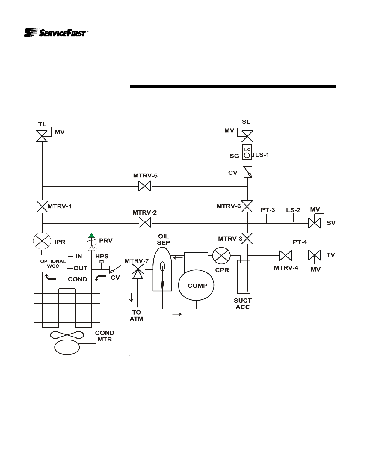
Figure 2. AllVac Schematic

RRGA-SVX01A-EN 9
Operation
Operating Procedures
To ensure your safety as well as others, before attempting to recover an A/C,
refrigeration or chiller system, proper and thorough preparation must take
place:
• Make sure you have a recovery cylinder with a minimum 3/4” male
flare vapor port and a minimum 3/4” male flare liquid port and 3/4” dip
tube. This tank or series of tanks must be able to hold the entire
refrigerant charge at 80% full. Both the tank and the refrigerant hoses
also must be pressure rated for the specific refrigerant being recov-
ered.
Reminder: Refrigerant full weight is 80% of water capacity weight
determined as follows: Maximum allowable gross weight = 80% of water
capacity weight + cylinder tare weight.
• In addition, a suitable scale should be used to weigh the tanks in case
AllVac needs to be shut down to prevent overfilling tanks. If a scale is
not available, the tanks can be equipped at time of purchase with a
float switch that will deactivate AllVac’s microprocessor control circuit
when the tank reaches 80% capacity.
• Finally, the recovery cylinder or cylinders must be pulled into a 29”
vacuum before recovery commences. Failure to follow these above
stated procedures will decrease the likelihood of AllVac performing at
its highest possible effectiveness.
1. Turn the A/C system off; make sure that the chiller cannot restart.
2. When using dual voltage model ARLH-A-D24-1-M connect has follows:
For 230-VAC, 1-phase power, connect the 50-ft., 230/460-VAC, 1-phase
power cord to a minimum 20 amp, maximum 30 amp circuit breaker or
fused disconnect and plug the quick connect Hubbell into AllVac’s control
box. When using 460-VAC, 1-phase power, connect the 50-ft., 230/460-
VAC, 1-phase power cord to a minimum 10 amp, maximum 20 amp cir-
cuit breaker or fused disconnect and plug the quick connect Hubbell into
AllVac’s control box. Connect the 100-ft., 120-VAC, 1-phase power cord
for controls. At this time, follow procedures 5 & 6 in selecting 1-phase
voltage, 230 or 460, failure to select proper voltage will result in major
damage to compressor motor. All other models connect to proper voltage
and required amperage as rated on equipment label.
3. At this point, the display lights up indicating the unit has power and
prompting you to press “Start”.

RRGA-SVX01A-EN 10
Operation
An additional feature can be accessed at this time, by pressing the “M” key.
This display will show you total compressor run time as well as give you a
historical maintenance schedule. In addition, at every 10 hours of cumulative
operating run time for the compressor, an automatic message will appear
each time you start the AllVac until maintenance is performed. After
changing oil, press the “Enter” key which records that maintenance has been
performed. Message will then not appear until the next 10 hours of
compressor run time is accumulated. The system will retain a log of each
maintenance event recorded.
4. AllVac then asks you to “Use M V To Select Scale or Float Switch”.
Scroll to either “Scale” or “Float Switch”, then press “Enter”.
Procedures 5 & 6 for ARLH-A-D24-1-M Model only
5. AllVac then asks you to “Use M V To Select Operating Voltage”. Scroll
to the desired voltage 230/460 using the “M V” keys, then press
“Enter”.
6. AllVac then tells you that “You Selected Single Phase ___V Operation
Is This Correct? Enter = Yes, Can = No”.
7. AllVac then asks you to “Select Refrigerant” being recovered. Scroll to
the desired refrigerant using the “M V” keys then press “Enter”.
8. AllVac then prompts you to check selection by displaying “Selected
Refrigerant R___ Is This Correct? Enter = Yes, Can = No”.
9. AllVac then prompts you to select the vapor transfer shutdown pressure
by “Use M V to select 0 PSI or 15 Hg Shutdown” for high pressure
refrigerants, or “Use M V to select 0 PSI or 29 Hg Shutdown” for low
pressure refrigerants. Scroll to the desired shutdown pressure, then press
“ENTER”.
10.AllVac then asks you to “Connect all Refrigerant Hoses” then press
“Enter”. Connect the two supplied 10-ft. hoses to AllVac’s recovery side
liquid and vapor ports and to liquid and vapor ports on the recovery cylin-
der. Connect the two supplied 20-ft. hoses to ports on the chiller evapora-
tor and condenser or A/C system and to the System Liquid and System
Vapor on AllVac unit as shown on Page 6.
• At this point, procedures for HIGH or LOW pressure refrigerant
recovery differ
For HIGH Pressure - follow steps 11 - 26
For LOW Pressure, go to page 7 follow steps 27 - 42
11. “Open System Vapor & Liquid Hand Valves on AllVac Recovery
Unit” then press “Enter”.
12.“Open Recovery Vapor & Liquid Hand Valves on AllVac Recovery
Unit” then press “Enter”.
Failure to select proper voltage
will result in major damage to
unit.
Caution
!

RRGA-SVX01A-EN 11
Operation
Note 1: If recovery tank side hoses have isolation valves, open them now.
13.“To Evacuate Hoses Press Enter, To Skip Hose Evacuation Press
Cancel” if “Enter” is pressed, unit displays “Hose Evacuation in Pro-
cess” followed by “Hose Evacuation Complete, Press Enter”.
14.Next “Open Vapor & Liquid Access Valves on A/C System Being
Recovered”then press “Enter”. If you pressed “Cancel” in step 13, All-
Vac will display “Purge Both Refrigerant Lines at the Recovery Tank”
then press “Enter”.
15.“Open Vapor and Liquid Hand Valves on Recovery Tank” then press
“Enter”.
16.AllVac then displays “Liquid Transfer!” and displays the A/C system and
recovery tank pressures.
• AllVac now begins automated recovery while continuously
displaying A/C system & recovery tank pressures.
Note 2: If additional liquid line is connected for faster liquid recovery, open A/
C system and recovery tank valves now. When AllVac goes into vapor
recovery, close recovery tank side of the hose.
17.Once pressure between the cooling system and recovery tank are within
15-psi of each other and a liquid sensor indicates that all liquid from liquid
transfer has been removed, the unit switches to vapor recovery, display-
ing “Vapor Recovery in Process” and continues to display the A/C sys-
tem & recovery tank pressures.
If AllVac does not switch to vapor recovery and you are absolutely sure that
all of the liquid has been removed, it may be because lines to the recovery
tank or to the cooling system are restricted. In this case, a bypass feature
can be accessed that forces the unit to begin vapor recovery. To perform this
task, press the enter key two times in a row during liquid recovery mode and
vapor recovery will commence. It is absolutely imperative that all liquid has
been transferred before using this override feature. Failure to do so may
result in liquid slugging to the compressor and causing major damage.
18.When the selected shutdown vacuum (either 0 PSI or 15” Hg) has been
achieved in the A/C system, the unit power shuts off and the display
reads “Vapor Recovery 2 Minute Wait State” and displays the time
remaining.
At this point, the microprocessor continues to monitor A/C system pressure.
Should pressure rise, AllVac restarts to again achieve the user selected
vacuum.
19.Then the display will read “Vapor Recovery Finished! press Enter”.

RRGA-SVX01A-EN 12
Operation
Upon pressing “Enter”, AllVac prompts you to perform the following
valve manipulations 20-26:
Note 3: Close additional liquid access valve at this time, if being used.
20.“Close Access Valves on A/C System Being Recovered” then
press”Enter”.
21.“Close Both Hand Valves on AllVac Unit A/C System Side” press
“Enter”.
22.AllVac compressor then restarts and begins to force remaining liquid in
AllVac as well as liquid in hose into the recovery tank. Displaying “Liquid
Refrigerant Clearing in Process”.
23.“Close Both Liquid & Vapor Hand Valves on Recovery Tank” press
Enter.
24.AllVac then begins evacuating the recovery tank vapor hose, displaying
“Hose Evacuation in Process”.
25.“Close Both Liquid & Vapor Tank Hand Valves on AllVac unit” then
press “Enter”.
26.Finally, the unit displays
“System Recovery Completed! Disconnect all Hoses and Power”.
At this time, close all four refrigerant hose isolation valves located on the
ends of the refrigerant hoses connected from AllVac to the recovery tank.
There will still be a small, residual amount of refrigerant in AllVac. This
amount must be removed if you want to change to a different type of
refrigerant. An explanation on how to remove this residual amount of
refrigerant is on page 14.
Low Pressure Section
27.Open Chiller Condenser & Evaporator Hand Valves on AllVac Unit” then
press “Enter”.
28.“Open Tank Vapor & Liquid Hand Valves on AllVac Recovery Unit”
then press “Enter”.
29.“To Evacuate Hoses Press Enter, To Skip Hose Evacuation Press
Cancel” if “Enter” is pressed, unit displays “Hose Evacuation in Pro-
cess” followed by “Hose Evacuation Complete, Press Enter”.
30.“Open Chiller Condenser & Evaporator Service Access Valves” then
press “Enter”.
31.Next “Open Vapor and Liquid Hand Valves on Recovery Tank” then
press “Enter”.
32.AllVac then displays “Liquid Transfer!” and displays the chiller pressure
and recovery tank pressures.

RRGA-SVX01A-EN 13
Operation
Note 4: If additional liquid line is connected for faster liquid recovery, open
chiller and recovery tank valves now. When AllVac goes into vapor recovery,
close recovery tank side of the hose.
33.AllVac will remain in liquid transfer state until manually switched to vapor
transfer as follows:
Once all liquid from chiller has been transferred and absolutely no liquid
refrigerant is remaining in clear recovery hoses and you are absolutely
sure that all of the liquid has been removed from the chiller, PRESS THE
ENTER KEY TWO TIMES IN A ROW. VAPOR RECOVERY WILL
COMMENCE. ALLVAC WILL DISPLAY “VAPOR RECOVERY IN
PROCESS” AND DISPLAY THE CHILLER AND RECOVERY TANK
PRESSURE. IT IS ABSOLUTELY IMPERATIVE THAT ALL LIQUID
HAS BEEN TRANSFERRED BEFORE SWITCHING TO VAPOR
RECOVERY MODE. FAILURE TO DO SO MAY RESULT IN LIQUID
SLUGGING THE COMPRESSOR AND CAUSING MAJOR DAMAGE.
34.When the user selected shutdown vacuum (either 0 PSI or 29” Hg) has
been achieved in the chiller system, the unit power shuts off and the dis-
play reads “Vapor Recovery 2 Minute Wait State”.

14 RRGA-SVX01A-EN
At this point, the microprocessor continues to monitor chiller pressure.
Should pressure rise, AllVac restarts to again achieve the user-selected
vacuum.
35.Then the display will read “Chiller Vapor Recovery Finished! press
Enter”.
Upon pressing “Enter”, AllVac prompts you to perform the following valve
manipulations 36 - 42:
Note 5: Close additional liquid access valve at this time, if being used.
“Close Both Service Access Valves on Chiller” then press”Enter”.
36.“Close Both Hand Valves on AllVac Unit Chiller Side” press “Enter”.
37.AllVac compressor then restarts and begins to force remaining liquid in
AllVac as well as liquid in hose into the recovery tank. Displaying “Liquid
Refrigerant Clearing in Process”.
38.“Close Both Liquid & Vapor Hand Valves on Recovery Tank” press
“Enter”.
39.AllVac then begins evacuating the recovery tank vapor hose, displaying
“Hose Evacuation in Process”.
40.“Close Both Liquid & Vapor Tank Hand Valves on AllVac unit” then
press “Enter”.
41.Finally, the unit displays “Chiller Recovery Completed! Disconnect all
Hoses and Power”.
At this time, close all four refrigerant hose isolation valves located on the
ends of the refrigerant hoses connected from AllVac to the recovery tank.
There will still be a small, residual amount of refrigerant in AllVac. This
amount must be removed if you want to change to a different type of
refrigerant. An explanation on how to remove this residual amount of
refrigerant is described in next paragraph.
Removing Remaining Residual Refrigerant
a) Connect the center tap of a manifold set to a suitable vacuum pump inlet
and discharge side of pump to an 50 lb. evacuated recovery cylinder. Con-
nect the low & high side of the manifold set to the 1/4” compressor suction
and discharge access ports located on the side of AllVac unit.
b) Open valve on 50 lb. recovery tank and turn on the vacuum pump. Open
the low & high side manifold valves and wait until a 29” vacuum has been
achieved on your manifold gauge.
c) Close both manifold valves, shut down vacuum pump and close recovery
tank valve. If you intend to use AllVac on a different type of refrigerant,
make sure to change compressor fluid and disposable driers.
Operation

RRGA-SVX01A-EN 15
Operation
Changing Replaceable Cores
Make sure you replace filter cores after each recovery job. Simply unscrew
used filter assembly and replace.
Procedures for Recharging System Using AllVac
These procedures provide for the transfer of refrigerant liquid and vapor from
a recovery tank to a centrifugal chiller system using the AllVac recovery unit.
These procedures are to be used when clean refrigerant is being returned to
a chiller without recycling.
When moving refrigerant between vessels, be certain that the pressure
never is greater than the vessel manufacturer’s recommendations.
Note: AllVac’s microprocessor displays instructions on the LCD screen as
recovery operations are implemented. During system recharging, the
references to the A/C System and the Recovery Tank are reversed.
Therefore, during recharging operations, the operator MUST assume that
the A/C System is now the Recovery Tank and the Recovery Tank is the A/C
System.
Select the desired vapor transfer stopping pressure, either zero (0) or 29”
Hg, for low pressure refrigerant.
1. Connect all liquid and vapor lines between chiller, AllVac recovery
unit and recovery tanks.
a) Refrigerant hoses should be connected in the following manner with all
valves in the closed position at this point:
Hose From To
Tank Vapor Tank AllVac System Vapor
Tank Liquid Tank AllVac System Liquid
Chiller Vapor Chiller AllVac Tank Vapor
Chiller Liquid Chiller AllVac Tank Liquid
Failure to adhere to the
procedures outlined herein can
cause severe damage to the
chiller. If liquid refrigerant is
introduced into the chiller while
the chiller is at deep vacuum, this
could result in tube freeze-up.
CAUTION
!

RRGA-SVX01A-EN 16
Operation
2. Evacuate Air from Chiller, AllVac and Hoses.
a) Once all lines are connected, open the AllVac valves in the following se-
quence: system liquid, system vapor, tank liquid, and tank vapor on AllVac
only.
b) Connect manifold gauge set and vacuum pump to ports on side of AllVac
unit at compressor suction and discharge ports.
c) Vacuum complete lines and AllVac to 29” Hg vacuum.
d) Close AllVac valves in the following sequence: system liquid, system va-
por, tank liquid, and tank vapor.
e) Disconnect manifold gauge and vacuum pump.
3. Increase Chiller Pressure Using Vapor From Recovery Tank.
(Refrigerant Vapor from the recovery tank is utilized to increase chiller
pressure at a controlled rate to prevent tube freeze-up when performing
procedure 4 below.)
a) Energize chiller condenser and evaporator water pumps. Water should be
flowing through both evaporator and condenser during this procedure to
reduce the potential for freezing chiller tubes.
b) Connect a vacuum gauge to the chiller.
c) Slowly open the specified valves in the following sequence:
(1) recovery tank vapor valve
(2) AllVac system vapor valve
(3) AllVac tank vapor valve
(4) chiller vapor valve
c) Continued. This step must be closely monitored manually at (4) chiller
vapor valve until the chiller pressure is sufficient to insure that it is above
freezing point for the refrigerant being transferred and until pressure has
equalized between the chiller and the recovery tank.
d) When pressure has equalized, close the specified valves in the following
sequence:
(1) chiller vapor valve
(2) recovery tank vapor valve
(3) AllVac system vapor valve
(4) AllVac tank vapor valve
4. Pump Liquid Refrigerant from Recovery Tank to Chiller
(Using AllVac to pump liquid refrigerant from recovery tank to chiller.)
a) Energize chiller condenser and evaporator water pumps. Water should be
flowing through both evaporator and condenser during this procedure to
reduce the potential for freezing chiller tubes.
During this procedure connect
the 120 VAC power for control
circuit to AllVac, but DO NOT
TURN THE ALLVAC UNIT ON until
this procedure 3 has been
completed and the pressure has
been equalized between the
chiller and the recovery tank AND
pressure is above the freezing
point.
Caution:
!
If liquid refrigerant is introduced
to the chiller when the pressures
are below the minimum levels as
noted in “b” below, severe
damage can occur due to freezing
of the chiller tubes.
Caution:
!

RRGA-SVX01A-EN 17
Operation
b) Before proceeding with this procedure, chiller pressure must be at a mini-
mum of 15” Hg. of vacuum or greater for R-11 or R-123. The minimum
pressure for R113 is 25” Hg. vacuum. If the chiller is not above the mini-
mum level, do not proceed with liquid transfer, but repeat procedure 3
above.
Do not continue this procedure until it is confirmed that chiller
pressure is above minimum required level.
c) Refrigerant hoses should be connected as follows:
Hose From To
Tank Vapor Tank AllVac System Vapor
Tank Liquid Tank AllVac System Liquid
Chiller Vapor Chiller AllVac Tank Vapor
Chiller Liquid Chiller AllVac Tank Liquid
d) Follow the procedures per the AllVac display, except you may ignore in-
structions to evacuate hoses at this time if hoses have already been evac-
uated per procedure 2 above.
Slowly open the specified valves in the following sequence:
(1) Recovery tank liquid valve
(2) AllVac system liquid valve
(3) AllVac tank liquid valve
(4) Chiller liquid valve
e) Monitor pressure in chiller condenser and evaporator. If pressure in chiller
becomes greater than 8 psig, shut down power to AllVac and remove non-
condensibles from chiller before resuming transfer.
f) Operate unit until all liquid refrigerant is removed from recovery tank. All-
Vac liquid sight glass, tank sight glass and liquid level gauge should all in-
dicate that all liquid refrigerant has been removed from the tank.
g) When all liquid refrigerant is removed from recovery tank, press “ENTER”
key two times on AllVac and vapor transfer from recovery tank will com-
mence. Continue to let AllVac run until vapor recovery is complete.

RRGA-SVX01A-EN 18
Operation
5. Evacuating Refrigerant Vapor From Recovery Tank and Hoses
(This step removes any liquid or refrigerant vapor in the recovery tank
and connecting hoses.)
a) Energize chiller condenser and evaporator water pumps. Water should be
flowing through both evaporator and condenser during this procedure to
reduce the potential for freezing chiller tubes.
b) AllVac provides for automated evacuation procedures of the recovery sys-
tem and hoses.
The operator reads the instructions provided by the microprocessor controls,
then performs the task described. This sequences each step for closing
valves and evacuating the AllVac and hoses
Important: AllVac’s microprocessor displays instructions on the LCD screen
as recovery operations are implemented. During system recharging, the
references to the A/C System and the Recovery Tank are reversed.
Therefore, during recharging operations, the operator MUST assume that
the A/C System is now the Recovery Tank and the Recovery Tank is the A/C
System.
c) Operate AllVac until tank vapor pressure gauge indicates a vacuum great-
er than 29” Hg for low pressure refrigerants.
Note: If, at any time, chiller pressure gauge indicates a value greater than 10
psig:
1. Compare chiller gauge reading with the saturated pressure shown in a
standard pressure/temperature chart for the type of refrigerant being
transferred. If the chiller pressure exceeds the saturated pressure indi-
cated for the type of refrigerant being transferred for the present chiller
temperature, it is actually an indication of the presence of air in the chiller.
2. If there is air in the chiller, the operator should use the chiller’s purge sys-
tem to remove the air before continuing and/or use RefTec’s portable
Minipurge. The Minipurge is an oil-less compressor driven purge which is
designed to purge non-condensibles from any refrigerant.
Note: If chiller pressure repeatedly rises above 10 psig, this indicates an air
leak in either the recovery tank or connecting hoses. If leakage cannot be
stopped at this time, terminate the operation.
d) Upon completion of the evacuation procedures, follow the instructions
according to the AllVac display to shut down unit.
e) Disconnect all power cables and hoses.

RRGA-SVX01A-EN 19
Calibration
Pressure Transducer Calibration Procedure
AllVac unit is equipped with a sensitive pressure transducer which needs to
be calibrated prior to running the AllVac. This will take into account variations
in atmospheric pressure at various altitudes and locations.
RefTec recommends that this calibration procedure be performed if any of
the following events occur:
a) Any time a new pressure transducer is installed on the unit.
b) Any time that the unit is moved to a substantially different altitude or is ex-
posed to significantly different atmospheric pressure.
c) Any time that pressure readings appear to be questionable or there is any
reason to doubt the accuracy of the transducer readings.
Calibration Procedure Steps:
1. At power up, the AllVac Recovery Unit will display:
“AllVac COMMERCIAL RECOVERY UNIT”
“HAS POWER (PRESS START)“
2. At this screen you must press “CANCEL” twice within 5 seconds to enter
the CALIBRATION mode. The display will then show the following:
“OPEN PRESSURE TRANSDUCERS TO ATMOSPHERE “
“(THEN PRESS ENTER KEY)”
3. Now, with no hoses connected, open the liquid and vapor, system and
recovery tank, valves on the AllVac to the atmosphere and press
“ENTER”.
4. The screen will then display the following message:
“SYSTEM PRESSURE xx PSI”
“PRESS ENTER TO CALIBRATE THIS TRANSDUCER"
The system is displaying the raw, uncalibrated reading from the transducer. If
you press “ENTER”, it will calculate a calibration value and store it in the
computer’s nonvolatile memory. If you press “CANCEL”, a new calibration
factor will not be calculated.
5. It will then display the following message:
“RECOVERY TANK PRESSURE xx HG”
“PRESS ENTER TO CALIBRATE THIS TRANSDUCER”
20 RRGA-SVX01A-EN
Calibration
The system is once again displaying the raw, uncalibrated reading from the
transducer. Once you press ENTER, it will calculate a calibration value for
this transducer and store it in memory. If you press “CANCEL”, a new
calibration factor will not be calculated. It will then display the following
message and be ready for operation:
“ALLVAC COMMERCIAL RECOVERY UNIT”
“HAS POWER (PRESS START) “
Changing Compressor Fluid
The compressor’s charge of Poly Ester fluid should be regularly replaced
with an identical fluid or, at a minimum, after any of these events:
1. After a maximum of 10 hours of run time
2. When changing recovery jobs that involve different refrigerants
3. After a recovering a system with a burnt out compressor.
To remove and change the oil in the compressor and the oil separator:
WARNING
a) Make sure AllVac unit has no refrigerant in its internal parts.
b) Connect a manifold set to dry nitrogen and to the suction and discharge
service 1/4” access ports located on the side of the AllVac.
c) Connect another 1/4” hose to the access fitting on the bottom of the AllVac
oil separator fitting and the other end to a suitable disposable oil container.
d) Gradually allow dry nitrogen to go into the discharge port on the AllVac unit
until all oil has been forced out of the oil separator. Note: 10 to 15 PSI will
be more than adequate.
e) Connect another 1/4” hose to the access fitting on the bottom of the AllVac
compressor fitting and the other end to a suitable disposable oil container.
f) Gradually allow dry nitrogen to go into the suction port on the AllVac unit
until all oil has been forced out of the compressor.
g) To add new oil to the AllVac compressor, connect a vacuum pump to the
1/4” access port on the suction side of the compressor. Pull down into a
minimum 29” vacuum.
h) Connect other hose to the 1/4” access port on the bottom of the compres-
sor and into the new oil container. Note: fill compressor with exactly 18 oz.
of oil.
i) After compressor has been filled, connect other hose to the 1/4” access
port on the bottom of the oil separator and into the new oil container. Note:
fill oil separator with exactly 16 oz. of oil.
j) Once this procedure is finished, remove all hoses and pull entire AllVac
into a 29” vacuum. Dispose of old oil properly.
ARNING
Note: Failure to follow above procedures for recharging oil in compressor
with the exact amount of oil may result in major damage to the compressor.
When changing oil, it is highly
recommended that the same type
of oil being used with the
refrigerant being recovered, be
used in the AllVac compressor.
This will help ensure that cross
contamination does not occur.
Caution:
!
This manual suits for next models
10
Table of contents


