ISA T1000 PLUS User manual

DATE: 29/11/2011 DOC.SIE91093 REV.7
SINGLE PHASE RELAY AND
MINIATURE CIRCUIT BREAKERS
TEST SET
MOD. T1000 PLUS
Shop for Power Metering products online at: 1.877.766.5412
www.PowerMeterStore.ca

DOC. SIE91093 Rev. 7 Page 3 of 37
APPLICABLE STANDARDS .........................................................................................................................................4
1 INTRODUCTION ....................................................................................................................................................... 5
2 CHARACTERISTICS ................................................................................................................................................8
2.1 MAIN GENERATOR.................................................................................................................................................... 8
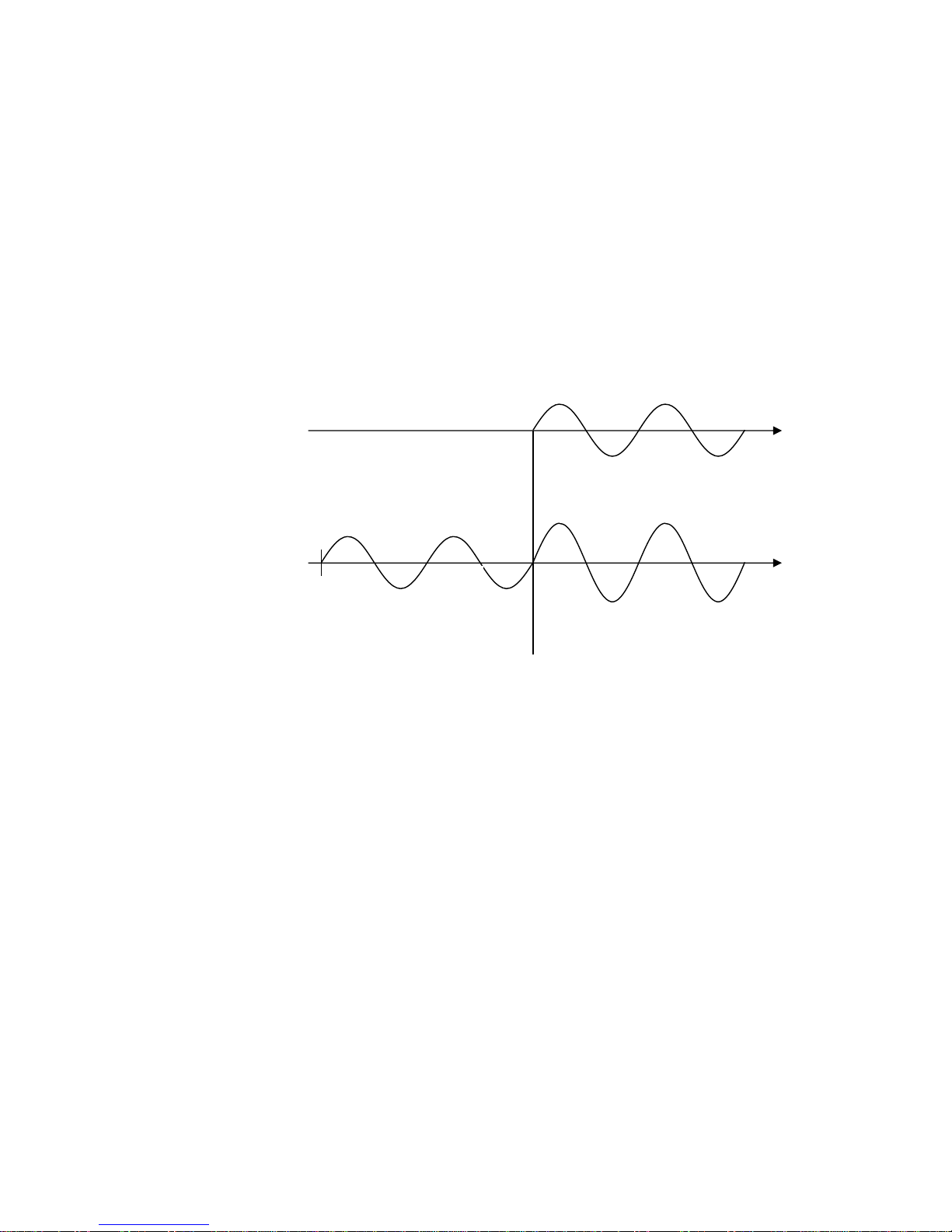
2.1.1 Main AC current............................................................................................................................................... 8
2.1.2 Main AC voltage ............................................................................................................................................... 9
2.1.3 Main DC voltage...............................................................................................................................................9
2.1.4 Other features of main outputs....................................................................................................................... 10
2.2 AUXILIARY AC VOLTAGE ....................................................................................................................................... 10
2.3 AUXILIARY DC VOLTAGE .................................................................................................................................... 13
2.4 TIMER ..................................................................................................................................................................... 14
2.5 TEST CONTROL........................................................................................................................................................ 15
2.6 AUXILIARY CONTACTS............................................................................................................................................. 16
2.7 OUTPUTS MEASUREMENT........................................................................................................................................ 17
2.7.1 Current and voltage ........................................................................................................................................ 17
2.7.2 Phase angle..................................................................................................................................................... 18
2.7.3 Other measurements....................................................................................................................................... 18
2.8 EXTERNAL INPUTS MEASUREMENT......................................................................................................................... 19
2.8.1 Current measurement..................................................................................................................................... 19
2.8.2 Voltage measurement...................................................................................................................................... 20
2.8.3 Other measurements....................................................................................................................................... 20
2.9 DISPLAY .................................................................................................................................................................. 21
2.10 MENU SELECTIONS................................................................................................................................................ 21
2.11 OTHER CHARACTERISTICS..................................................................................................................................... 27
2.12 OPTIONS ................................................................................................................................................................ 29
2.12.1 Power supply, code PII81093 ....................................................................................................................... 29
2.12.2 Connection cable kit, code ZII18093............................................................................................................ 29
2.12.3 Transit case, code PII17093 ......................................................................................................................... 29
2.12.4 “E” model: higher AC voltage outputs, code PII92093............................................................................... 30
2.12.5 D1000 differential relay test module, code PII40093 .................................................................................. 30
2.12.6 TD1000 PLUS model: auxiliary AC current output, code PII94093.......................................................... 30
2.12.7 TD1000 PLUS 15Hz model: higher power at low frequency, code PII93093............................................. 31
2.12.8 FT/1000 current filter, code PII16093......................................................................................................... 32
2.12.9 SHA-1000 scanning head for T1000 PLUS and T3000, code PII43102..................................................... 32
2.12.10 Outputs transducer and connection cables for low level signal relays..................................................... 33
3 PROTECTIONS ........................................................................................................................................................ 35
APPENDIX 1: AUXILIARY AC OUTPUT FEATURES COMPARISON .............................................................. 36
APPENDIX 2: MENU SELECTIONS FLUX DIAGRAM......................................................................................... 37
Shop for Power Metering products online at: 1.877.766.5412
www.PowerMeterStore.ca

DOC. SIE91093 Rev. 7 Page 4 of 37
APPLICABLE STANDARDS
The test set conforms to the EEC directives regarding Electromagnetic Compatibility and Low
Voltage instruments.
A) Electromagnetic Compatibility:
Directive no. 2004/108/EC. Applicable Standard : EN61326-1 + A1 + A2.
EMISSION
- EN 61000-3-2: Harmonic content of power supply. Acceptable limits: basic.
- EN 61000-3-3: Limitation of voltage fluctuations and flicker. Acceptable limits: basic.
- CISPR16 (EN 55011 class A): Limits and measurement methods of radio-electric disturbances for
industrial, medical and scientific instruments at radio-electric frequencies.
Acceptable limits for conducted emission:
. 0.15-0.5 MHz: 79 dB pk; 66 dB avg.
. 0.5-5 MHz: 73 dB pk; 60 dB avg.
. 5-30 MHz: 73 dB pk; 60 dB avg.
Acceptable limits for radiated emission:
. 30-230 MHz: 40 dB (30 m)
. 230-1000 MHz: 47 dB (30 m)
IMMUNITY
- EN 61000-4-2: Immunity tests for ESD. Test values: 8 kV in air; 4 kV in contact.
- EN 61000-4-3; Immunity tests for radio frequency interference. Test values (f= 900 5 MHz):
field 10 V/m, modulated AM 80%; 1 kHz
- EN 61000-4-4; Immunity tests for high speed transients (burst). Test values: 2 kV peak; 5/50 ns.
- EN 61000-4-5; Immunity tests for surge. Test values: 1 kV peak differential mode; 2 kV peak
common mode; 1.2/50 us.
- EN 61000-4-6: immunity to low-voltage sinusoidal waveform. Test values: 0.15-80 MHz, 10
Vrms, 80% AM 1 kHz.
- EN 61000-4-8: Immunity tests for low frequency magnetic fields. Test values: 30 Arms/m.
- EN 61000-4-11: Immunity test for power supply drops. Test value: 1 cycle; 100% drop.
B) Low Voltage Directive:
- - Directive n. 2006/95/EC.
- Applicable standard: EN 61010-1. In particular, for a pollution degree 2: dielectric rigidity 1.4 kV
AC, 1 minute.
- Inputs/outputs protection: IP 2X - EN60529.
- Operating temperature: 0 to 50 °C; storage: -20 °C to 70 °C.
- Relative humidity: 5 - 95%, without condensing.
- Vibration: IEC 68-2-6 (20 m/s^2 at 10 –150 Hz);
- Shock: IEC 68-2-27 (15 g; 11 ms; half-sine).
- Altitude: less than 2000 m.
Shop for Power Metering products online at: 1.877.766.5412
www.PowerMeterStore.ca

DOC. SIE91093 Rev. 7 Page 5 of 37
1 INTRODUCTION
The relay test set mod. T1000 PLUS is suited for the testing and adjustments of Low Voltage
Miniature Circuit Breakers and of the following types of relays.
:
Distance protection (phase by phase) (21, *)
Synchrocheck (25)
Thermal (26)
Undervoltage and overvoltage (27, 59)
Directional power (32)
Undercurrent (37)
Negative sequence overcurrent (46)
Phase sequence voltage relay (47)
Incomplete sequence relay (48)
Definite time overcurrent (50- 50N)
Time dependent overcurrent (51 - 51N)
Power factor (55)
Directional overcurrent (67)
Directional earth fault (67N)
Automatic reclosing devices (79)
Frequency (81<, 81>)
Load shed (frequency ROC, 81R)
Motor overload protection (86)
Differential (87)
Directional voltage (91)
Tripping relays (94)
In addition to the above, T1000 PLUS can test:
. Converters: V; I; φ°; p.f.; W; VAr; f., both 0 to 5 and 4 to 20 mA.
. Energy meters, single phase or three phase.
T1000 PLUS is also suited to perform the following tests:
Finding the CT saturation knee;
Current and voltage transformer ratio test;
Burden measurement of the protective relay test equipment;
Impedance measurement;
Polarity (direction) tests;
Timed fault injection;
Off delay - possibility to time delay the turning-off of generation after
tripping.
In addition, T1000 Plus features:
o Reduced power operation, for the fine current regulation;
o Fine voltage regulation;
o Display the values of: current, AC voltage, DC voltage, time, and of derived
measurements.
o Freeze function (HOLD) for voltage and current readings.
o The timer has separated inputs for start and stop impulses.
o The timer start and stop inputs respond to changes (EDGE).
o Start and stop input levels are displayed by LED’s.
Shop for Power Metering products online at: 1.877.766.5412
www.PowerMeterStore.ca

DOC. SIE91093 Rev. 7 Page 6 of 37
o The relay intervention is displayed by an LED.
o Test modes: ON, ON+TIME, OFF+TIME.
o The device is provided with USB and serial port for the communication to the
computer (notebook).
o The TDMS Windows compatible software allows setting, testing and storing (also in
a built-in Data Base) all data. Printing plus exporting report results in Words, Excel,
PDF formats.
o TDMS is upgraded for free in the ISA WEB site.
o Main output adjustments: 0-250 A AC, 0-250 V AC (T1000E: 0-500 V AC), 0-300
V DC.
o Auxiliary AC voltage source, range 0-260 V AC (T1000E: 0-500 V AC), 0-359°
phase shift, 15 to 550 Hz, separated from the other outputs with independent
settings. Optional TD1000PLUS model: also an output of 0-20 A AC, phase and
frequency adjustable.
o Auxiliary DC voltage source; range 20-240 V DC. Equipped with overload
protection, and separated from the other outputs.
o Auxiliary AC and DC voltage sources can be turned ON and OFF via
pushbuttons.
o Two auxiliary relay contacts, that can be independently timed with respect to test
start and stop.
The instrument contains three separate generators:
. Main generator: it generates either AC current, AC voltage; DC voltage;
. Auxiliary AC voltage generator: it generates an independent, phase adjustable AC voltage;
. Auxiliary DC voltage generator: it generates the DC voltage that feeds the relay under test.
All outputs are adjustable and metered at the meantime on the large, graphic LCD display. With the
multi-purpose knob and the LCD display it is possible to enter the MENU mode, which allows
setting many functions, which make T1000 PLUS a very powerful testing device, with manual and
semi-automatic testing capabilities, and with the possibility to transfer test results to a PC via the
RS232 interface. These results can be recorded, displayed and analysed by the powerful TDMS
software, which operates with all WINDOWS versions, starting from WINDOWS 98 included.
The basic T1000 PLUS function is to generate current and voltages and to stop generation as the
relay trips. Test results are kept in memory, and can be transferred to a PC at a later time, along
with settings.
The ease of operation has been the first goal of T1000 PLUS: this is why the LCD is graphic, and so
large. With it, the dialogue in MENU mode is made easy. Besides, all T1000 PLUS outputs are
continuously measured, and output values are displayed, with no extra effort to the operator. Also
the show waveform feature can be of help: any doubt about strange measurements, distortion and so
on can be solved.
This is also why we have added the reduced power feature. Modern relays have a very low burden.
As current output is a low impedance voltage generator, adjusting low currents and/or current on
low burdens is quite difficult because one has to operate at the very beginning of the adjustment
knob. In this situation it is possible to connect resistors in series; however, one must be careful not
to exceed the maximum current rating, and the wiring is more complicated. The solution to this
problem is just to reduce the available power: this is easily performed via the multi-function knob.
With less power, the maximum voltage is reduced by a factor of five; the adjustment span on the
knob is increased accordingly.
Shop for Power Metering products online at: 1.877.766.5412
www.PowerMeterStore.ca

DOC. SIE91093 Rev. 7 Page 7 of 37
The instrument is housed in a transportable aluminium box, which is provided with removable
cover and handles for ease of transportation.
The test set is shown here below.
NOTE: WINDOWS is a trademark of MICROSOFT Inc.
Shop for Power Metering products online at: 1.877.766.5412
www.PowerMeterStore.ca

DOC. SIE91093 Rev. 7 Page 8 of 37
2 CHARACTERISTICS
2.1 MAIN GENERATOR
The main generator has three outputs: currents, voltage AC, voltage DC. The following
specification applies to the separate usage of these outputs. It is possible to use them at the
meantime, provided that the total maximum load is not exceeded.
The main generator is made of a variable transformer followed by a transformer. The variable
transformer does not reach the zero position; so, when you are adjusting the output current on a low
burden, the minimum current can be up to 5% of the range. If this is a problem, select the 60 VA
power: the current is reduced to one fifth.
For all main output generators there is no specification related to the output distortion. This is
because the output waveform follows the mains supply waveform, with its distortion. If it is desired
to avoid distortions, the option FT100 solves the problem.
2.1.1 Main AC current
- Type of generator: voltage, high current output: the current depends upon the burden.
-On all outputs is provided the capability of generating the selected current at maximum power or
at reduced power. Reduced power selection eases the current adjustment for modern relays, where
the load is negligible. Current ranges; available power; duty cycle: see the table below.
1) MAXIMUM POWER 300 VA
RANGE
A AC
CURRENT
OUTPUT
A
MAXIMUM
POWER
VA
LOAD
TIME
s
RECOVERY
TIME
min
100
30
300
STEADY
-
50
30 min
100
75
600
45
100
800
60
15
150
3
10
250
1000
1
5
40
12
300
STEADY
-
20
30 min
100
30
600
45
40
800
60
15
60
3
10
80
1000
1
5
10
5
400
STEADY
-
7.5
15 min
45
10
800
60
15
15
5
10
20
1000
2
5
2) MAXIMUM POWER 60 VA
RANGE
CURRENT
MAXIMUM
LOAD
RECOVERY
Shop for Power Metering products online at: 1.877.766.5412
www.PowerMeterStore.ca

DOC. SIE91093 Rev. 7 Page 9 of 37
A AC
OUTPUT
A
POWER
VA
TIME
s
TIME
min
100
30
60
STEADY
-
38
10 min
45
53
60
10
70
0.75
2
40
12
60
STEADY
-
17
10 min
45
23
60
10
36
1
2
10
5
60
STEADY
-
6
10 min
45
7
60
2
10
1,5
2
- Power selection: via menu.
- Connection: four high power sockets, with safety protections, marked: 0; 10 A; 40 A; 100 A.
2.1.2 Main AC voltage
- The main AC voltage is isolated from the main AC current.
-AC voltage range: 250 V or 54 V (reduced power; power supply 230 V), or 108 V (reduced
power; power supply 110 V).
- Available power and duty cycle: see table below.
RANGE
V AC
VOLTAGE
OUTPUT
V
LOAD
CONSUMPTION
VA
LOAD
TIME
min
RECOVERY
TIME
min
REDUCED
POWER
250
250
500
STEADY
-
NO
250
750
10
45
NO
54 (108)
54 (108)
60
STEADY
-
YES
- Connection: two safety banana sockets.
2.1.3 Main DC voltage
- The main DC voltage is isolated from the main AC current, but not from the main AC voltage
-DC voltage range: 300 V or 60 V (reduced power; power supply 230 V), or 120 V (reduced
power; power supply 110 V).
- Available power and duty cycle: see table below.
Shop for Power Metering products online at: 1.877.766.5412
www.PowerMeterStore.ca

DOC. SIE91093 Rev. 7 Page 10 of 37
RANGE
V DC
VOLTAGE
OUTPUT
V
LOAD
CONSUMPTION
W
LOAD
TIME
min
RECOVERY
TIME
min
REDUCED
POWER
300
300
300
STEADY
-
NO
300
500
10
45
NO
60 (120)
60 (120)
60
STEADY
-
YES
- Type of DC voltage: unregulated, via diode bridge rectifier and capacitor.
- Connection: two safety banana sockets.
2.1.4 Other features of main outputs
- Zero crossing control. Main AC outputs are generated and stopped as the output waveform crosses
zero. This implies that in mode ON+TIME the output drops to zero from 0 to one cycle after STOP
is detected.
- Overload alarm message. When the nominal current range is trespassed a message is displayed.
- Thermal protection: by NTC. Trespassing of the maximum temperature is signalled by a message.
- Output adjustment: from less than 5% to 100% of the output.
- Output measurement. The used output (current, V AC, V DC) is selected by a dedicated push-
button; the selected socket is confirmed by a light.
2.2 AUXILIARY AC VOLTAGE
- The auxiliary AC voltage output, V AC aux, is isolated from the main AC current and voltage.
- Output ranges: 65 –130 - 260 V. NOTE: at 15 Hz, the output ranges are: 25, 50, 100 V.
- Range selection: software driven, by the multi-function knob and LCD display.
- Auxiliary voltage power: 30 VA, continuous duty, at full range; 40 VA for 1 minute. At 15 Hz, the
power is: 8.5 VA at 25 V; 13 VA at 50 V; 16 VA at 100 V. For lower voltages the limiting current
is the following.
RANGE
V
MAX CURRENT
mA; > 40 Hz
MAX POWER
VA; > 40 Hz
RANGE
V; 15 Hz
MAX CURRENT
mA; 15 Hz
MAX POWER
VA; 15 Hz
65
500
30 (40)
25
350
8.5
130
250
30 (40)
50
260
13
260
125
30 (40)
100
160
16
- Output stability: the adjusted voltage drops of 5% maximum from zero load to full load.
- Output adjustment: continuous. For normal tests the voltage is continuously supplied, and the
output voltage is adjusted by the dedicated knob.
- Output connection: safety banana sockets.
- ON-OFF switch to enable the output. A light confirms when the output is available.
Shop for Power Metering products online at: 1.877.766.5412
www.PowerMeterStore.ca

DOC. SIE91093 Rev. 7 Page 11 of 37
- Possibility to phase shift the auxiliary AC voltage output with respect to: the main current and the
main AC voltage. The phase angle reference is the auxiliary voltage. Phase shifter characteristics:
. Phase angle adjustment: via the multi-function knob.
. Phase angle range: from 0° to 360°.
. Adjustment resolution: 1° (degree).
- Possibility to define the pre-fault voltage: in this mode, the control knob allows to adjust the pre-
fault value, while the dedicated knob adjusts the fault value. Voltage output selection is automatic:
pre-fault voltage with test stopped; fault voltage with test started. The switch from a value to the
other one is performed without falling to zero. The main current or voltage is generated at the zero
crossing; the fault one is generated at the meantime of main voltage or current (figure 1). The
selection of the reference is performed automatically, following the selection of main output
measurement. If the main DC voltage is selected the reference is taken on the main AC voltage.
This feature allows testing voltage relays (27-59) or synchronizing relays (25).
MAIN AC CURRENT
(MAIN AC VOLTAGE)
AUXILIARY
VOLTAGE
TEST START
Figure 1 - Output voltage control
- Possibility to phase shift the pre-fault voltage, at an angle independent from the fault voltage. This
parameter serves during the test of distance relays, when phase to phase faults are simulated: as test
starts, the fault voltage changes amplitude and phase with respect to the pre-fault value (figure 2)
Shop for Power Metering products online at: 1.877.766.5412
www.PowerMeterStore.ca

DOC. SIE91093 Rev. 7 Page 12 of 37
V1 PRE-FAULT
V1 FAULT
FAULT ANGLE
V1 FAULT
PRE-FAULT ANGLE
I1 FAULT
V2 V3
Figure 2 –Prefault voltage
- Possibility to define the duration TPF of pre-fault generation, after test start, prior to generating
fault values. This feature is necessary to test synchronization relays: the main output voltage can be
applied prior to frequency switching. TPF range: from 0 to 999.99 s.
- Possibility to change the frequency of the auxiliary AC voltage output. Frequency generation
characteristics:
. Frequency range: 15.000 Hz to 550.000 Hz.
. Frequency adjustment: 1 mHz, via control knob.
. Frequency generation error: 100 ppM.
. It is possible to switch from the nominal frequency to the fault one. The nominal frequency is also
selectable, independently from the fault.
. Switching from nominal frequency to fault frequency is performed without altering the output
voltage (figure 3).
TEST
OFF
ON + TIME
V1 AMPLITUDE
VN
V2 AMPLITUDE
VN
V2 FREQUENCY
FN
FTEST
PRE-FAULT TIMING
T PF
TIMING MEASUREMENT
FN
Shop for Power Metering products online at: 1.877.766.5412
www.PowerMeterStore.ca

DOC. SIE91093 Rev. 7 Page 13 of 37
Figure 3 - Frequency relay test waveform
- Possibility to test frequency rate of change relays. Frequency ROC range: from 0.01 to 99.99 Hz/s.
The frequency change stops at 40 or 70 Hz.
2.3 AUXILIARY DC VOLTAGE
- The auxiliary DC voltage output, V DC aux, is isolated from the main AC current and voltage and
from the auxiliary AC voltage output.
- DC voltage ranges: 130 V or 240 V.
- Output adjustment: continuous, by knob, from 20 V to the selected range.
- ON-OFF switch to enable the output. A light confirms when the output is available.
- DC voltage power: 90 W at full range, continuous duty, with a current limit of 0.9 A @ 130 V and
0.45 A @ 240 V.
- DC output accuracy:
. For mains supply variations: ± 1%;
. For load changes: ± 1%;
. Residual ripple: 1%.
- Output connection: on safety banana sockets.
V
V
t
t
t
t
Hz
Hz
50
50
40
60
2A) Underfrequency
2B) Overfrequency
Shop for Power Metering products online at: 1.877.766.5412
www.PowerMeterStore.ca

DOC. SIE91093 Rev. 7 Page 14 of 37
2.4 TIMER
The electronic digital timer has a fully automatic start and stop, both for make and break of the
input, which can be either a clean contact or a contact under voltage. All selections are menu-driven
via the multi-function knob.
- Characteristics of Start and Stop inputs:
.. Inputs do not have any common point, and are opto-coupled from the instrument at 1.35 kV AC;
.. Inputs connection: two banana sockets per input;
.. Inputs may be independently selected as Normal Open or Normal Close;
.. It is also possible to select timer start or stop as the current is injected and timer start/stop on input
transition;
.. Selections are displayed on the front panel by 10 dedicated lights;
.. Type of input: either clean or under voltage; selection via the multi-function knob. Maximum
input: 250V AC or 275 V DC;
.. For both inputs, when the input is closed or with voltage an LED turns on;
.. When the relay intervenes, the TRIP light turns on;
.. Wrong selection protection. If a voltage is applied when the clean input is selected, input circuits
are not damaged.
- Input thresholds: when the contact has voltage applied, two thresholds can be selected. The low
setting applies to nominal voltages of 24 and 48 V; the high setting to 110 V up.
With voltage
Parameter
Nominal value
Unit
Low setting
12
V DC
High setting
80
V DC
Without voltage
Parameter
Nominal value
Unit
Nominal wetting voltage
24
V
Nominal wetting current
10
mA
- Available measurements:
. Timer start: at test start, or by an external contact;
. Metering of elapsed time between START and STOP.
- Time can be metered as seconds or cycles. Metering range, in seconds: see table.
Range
Resolution
Accuracy
From 0 to 9.999 s
1 ms
± (1 ms + 0.005%)
From 10.00 to 99.99 s
10 ms
± (10 ms + 0.005%)
From 100.0 to 999.9 s
100 ms
± (100 ms + 0.005%)
From 1000 to 9999 s
1 s
± (1 s + 0.005%)
. Metering range, in cycles, selectable at 50 Hz or at 60 Hz.
Range
Resolution
Accuracy
From 0 to 999.9
0.1 cycles
± (0.1 cycles + 0.005%)
Shop for Power Metering products online at: 1.877.766.5412
www.PowerMeterStore.ca

DOC. SIE91093 Rev. 7 Page 15 of 37
(Equal to 19.998 s @ 50 Hz;
16.665 s @ 60 Hz)
From 1000 to 499,998.5 cycles @ 50
Hz;
From 1000 to 599,998 cycles @ 60
Hz
(Equal to 9999 s)
1 cycle
± (1 cycle + 0.005%)
- Display reset: automatic, at test start.
- Counting mode: this mode is foreseen for the test of energy meters. Maximum input frequency: 10
kHz; voltage threshold can be set as for tripping. It is possible to select this mode via menu, and to
set the number of impulses; the test set counts all impulses applied to START input after ON and
during all generation, and measures the time elapsed during the count.
2.5 TEST CONTROL
- Manual start control:
. OFF: main outputs are not generated; V AC aux is generated, and it can be either the pre-fault
value or the fault value, according to selections; V DC aux is generated.
. ON: main outputs are generated; Vac aux has the fault value. In this situation it is possible to
verify and memorize the relay threshold, both trip and reset.
. From OFF to ON + time: main outputs are generated and the timer starts according to selections;
as STOP is sensed, main outputs are removed and the elapsed time displayed and test result can be
memorized.
. From ON to OFF + time: main outputs are removed the timer starts according to selections; as
STOP is sensed, the elapsed time is displayed and test result can be memorized.
. Test control: by two push-buttons.
- Other test control selections:
. Momentary: in ON mode, main outputs are generated until the push-button is pressed;
. Timed: main outputs are generated for the programmed maximum time;
. External. This mode allows for the synchronization of more T1000 PLUS.
- Reclose test. It is possible to select via menu the test of a reclosing scheme. Two selections are
available, according to the type of the recloser under test.
In the first operating mode, T1000 PLUS is connected as follows: Trip command to the STOP
input; Close command to the START input. As Close is detected, the test set automatically applies
current with the programmable reclaim time delay TD. The test set measures and stores the relay
trip delay and the delay between trip leading or falling edge and CLOSE trailing edge (see figure 4).
The sequence is repeated the programmed N times; after this, a last fault is issued, and the test set
verifies that there is no Close command.
Shop for Power Metering products online at: 1.877.766.5412
www.PowerMeterStore.ca

DOC. SIE91093 Rev. 7 Page 16 of 37
FAULT 1 2
TRIP (STOP) 1 2
CLOSE (START) 1 2
TIME MEASUREMENTS D1 R1 D2 R2
TD
Figure 4: Measure of Delay and Close times
The second operating mode refers to pole mounted CB’s. In this mode, there is only one signal
coming from the device under test: the position of the CB. In this mode, the operation is the
following.
In this test mode the test set is edge triggered; the CB position is connected to the STOP input, and,
from the Closed –Open position, the test set derives the fault generation commands, to perform the
test as above.
The following specification applies to both operating modes.
- Range of TD: from 0 to 999.9 s. Maximum number of Reclose commands: 49; maximum test
duration for all Reclose commands: 9999 s.
- Circuit breaker delay simulation: possibility to set the delay from relay trip to generation off.
Delay range: 0 to 999 ms or 0 to 999 cycles.
- Save selections:
. No automatic saving.
. Test data can be saved after confirmation. After relay trip, pressing the multi-function knob it is
possible to save the test result.
2.6 AUXILIARY CONTACTS
- Two auxiliary make and break contacts.
- Each contact can be separately programmed to close (open) at test start, or after a programmable
delay. Contacts switch off when the STOP input is sensed.
OPEN
CLOSED
FAULT
Shop for Power Metering products online at: 1.877.766.5412
www.PowerMeterStore.ca

DOC. SIE91093 Rev. 7 Page 17 of 37
- Delay range with respect to test start: from 0 to 999.99 s.
- Maximum time error between current and make/break contact: 2 ms.
- Contacts range: 5 A; 250 V AC; 120 V DC
2.7 OUTPUTS MEASUREMENT
2.7.1 Current and voltage
- The following three outputs are displayed at the meantime on the LCD display:
. The selected main output: AC current, or AC voltage, or DC voltage;
. Auxiliary AC voltage output;
. Auxiliary DC voltage output.
- Type of measurement: true rms for AC outputs; average for DC outputs.
- Readings, resolution and accuracy: see table. Note that the available ranges can be greater than the
maximum value of the socket to which the load is connected: this means that higher values can be
measured without saturation. For example, on the 100 A output the measuring range is up to 999 A.
Actually, the test set will not generate more than 250 A, as the test is stopped by the software, that
indicates overload, and on the display currents more than 250 A will not be shown.
OUTPUT
RANGE
RANGE
CHANGE
RESOLUTION
ACCURACY
10 A
1.999 A
1.5 A
1 mA
± (1% + 5 mA)
19.99 A
10 mA
± (1% + 20 mA)
40 A
7.999 A
6 A
4 mA
± (1% + 20 mA)
79.99 A
40 mA
± (1% + 80 mA)
100 A
19.99 A
15 A
10 mA
± (1% + 50 mA)
199.9 A
150 A
100 mA
± (1% + 200 mA)
249.9 A
100 mA
± (1% + 200 mA)
250 V AC
1.999 V
1.5 V
1 mV
± (1% + 50 mV)
19.99 V
15 V
10 mV
± (1% + 50 mV)
199.9 V
150 V
100 mV
± (1% + 200 mV)
299.9 V
300 mV
± (1% + 300 mV)
300 V DC
1.999 V
1.5 V
1 mV
± (0.5% + 20 mV)
19.99 V
15 V
10 mV
± (0.5% + 50 mV)
199.9 V
150 V
100 mV
± (0.5% + 200 mV)
299.9 V
(599.9 V)
300 mV
± (0.5% + 300 mV)
65, 130 V AC
1.999 V
1.5 V
1 mV
± (1% + 10 mV)
19.99 V
15 V
10 mV
± (1% + 20 mV)
59.99 V
45 V
10 mV
± (1% + 50 mV)
199.9 V
100 mV
± (1% + 200 mV)
260 V AC
1.999 V
1.5 V
1 mV
± (1% + 10 mV)
19.99 V
15 V
10 mV
± (1% + 20 mV)
199.9 V
150 V
100 mV
± (1% + 200 mV)
Shop for Power Metering products online at: 1.877.766.5412
www.PowerMeterStore.ca

DOC. SIE91093 Rev. 7 Page 18 of 37
299.9 V
300 mV
± (1% + 300 mV)
130 V DC
19.99 V
15 V
10 mV
± (0.5% + 100 mV)
199.9 V
100 mV
± (0.5% + 200 mV)
240 V DC
19.99 V
15 V
10 mV
± (0.5% + 100 mV)
199.9 V
150 V
100 mV
± (0.5% + 200 mV)
299.9 V
(599.9 V)
300 mV
± (0.5% + 300 mV)
NOTES:
- The range change is the value at which the range is changed. This value is less than full range in
order to avoid saturation problems when we have to measure fast-changing values.
- Metering temperature coefficient: ± 0.05%/°C of the value ± 0.02%/°C of the range.
- Via menu selections, the metering can also be referred to the nominal current or voltage. In this
situation the following applies.
OUTPUT
NOMINAL
VALUE
RANGE
NOMINAL
VALUE
STEP
MEASUREMENT
RANGE %
RESOLUTION
%
ACCURACY
%
CURRENT
1 –999 A
1 A
99.9
0.1
0.1
999
1
1
VOLTAGE
AC
1 –999 V
1 V
99.9
0.1
0.1
999.9
1
1
- Measurement options: see the MENU paragraph.
2.7.2 Phase angle
- The auxiliary voltage is the reference for the measurement of the phase shift of one of the
following parameters:
. The main current;
. The main AC voltage;
. The mains supply.
- Readings, resolution and accuracy: see table.
MEASUREMENT
RANGE
RESOLUTION
ACCURACY
PHASE
0 - 360
1°
1° ± 1 DIGIT *
* Specified accuracy applies for outputs I,V or V,V greater than 20% of the selected range.
- Phase angle temperature coefficient: ± 1 ppM/°C of the value.
2.7.3 Other measurements
Starting from the above measurements, the test set can compute derived measurements; the
selection is performed via the control knob.
Shop for Power Metering products online at: 1.877.766.5412
www.PowerMeterStore.ca

DOC. SIE91093 Rev. 7 Page 19 of 37
The following is the list of available measurements. For all of them the following range and
resolution applies; the accuracy is the sum of voltage, current and possibly angle accuracy.
PARAMETER RANGE; X
IS THE MEASURED ENTITY
RESOLUTION
0 –999 mX
0,001 X
1.00 –9.99 X
0,01 X
10.0 –99.9 X
0,1 X
100 –999 X
1 X
1.00 –9.99 kX
10 X
10.0 –99.9 kX
100 X
100 –999 kX
1000 X
N.
PARAMETER , AC outputs
DERIVED
FROM
FORMULA
UNITS
1
ACTIVE POWER, P
Imain, Vac aux; φ
P= I*V*cos (φ)
W
REACTIVE POWER, Q
Imain, Vac aux; φ
Q= I*V*sin(φ)
VAr
2
APPARENT POWER, S
Imain, Vac aux
S= I*V
VA
POWER FACTOR, p.f.
φ
p.f. = cos(φ)
-
3
IMPEDANCE, Z and φ
Imain, Vac aux, φ
Z = V/I
Ohm, °
4
ACTIVE IMPED. COMPONENT, R
Imain, Vac aux; φ
R = Z* cos(φ)
Ohm
REACTIVE IMPEDANCE COMP., X
Imain, Vac aux; φ
X = Z* sin(φ)
Ohm
2.8 EXTERNAL INPUTS MEASUREMENT
- It is possible to meter the current and the voltage of an external (or internal) generator.
- Input connection: by five safety sockets; three for current and two for voltage.
- Metering circuits are 1.35 kV isolated between them and from the rest of the instrument.
2.8.1 Current measurement
- Maximum input current. Two inputs: 20 mA or 10 A, AC or DC
- Range, resolution, accuracy: see table below.
RANGE 20 mA
RESOLUTION
ACCURACY
25 mA DC
0.1 mA
± (0.5% + 0.1 mA)
RANGE 10 A
CHANGE RANGE
RESOLUTION
ACCURACY
1.999 A AC
1.5 A
1 mA
± (1% + 2 mA)
10.49 A AC
10 mA
± (1% + 20 mA)
1.999 A DC
1.5 A
1 mA
± (0.5% + 2 mA)
10.49 A DC
10 mA
± (0.5% + 20 mA)
- Metering temperature coefficient: ± 0.05%/°C of the value ± 0.02%/°C of the range.
- Possibility to display the current waveform.
Shop for Power Metering products online at: 1.877.766.5412
www.PowerMeterStore.ca

DOC. SIE91093 Rev. 7 Page 20 of 37
2.8.2 Voltage measurement
- Maximum input voltage: 600 V, AC or DC
- Range, resolution and accuracy: see table below.
RANGE
RANGE
CHANGE
RESOLUTION
ACCURACY
19.99 V AC
15 V
10 mV
± (1% + 20 mV)
59.99 V AC
45 V
10 mV
± (1% + 60 mV)
199.9 V AC
150 V
100 mV
± (1% + 200 mV)
599.9 V AC
100 mV
± (1% + 600 mV)
19.99 V DC
15 V
10 mV
± (0.5% + 20 mV)
59.99 V DC
45 V
10 mV
± (0.5% + 60 mV)
199.9 V DC
150 V
100 mV
± (0.5% + 200 mV)
599.9 V DC
100 mV
± (0.5% + 600 mV)
- Metering temperature coefficient: ± 0.05%/°C of the value ± 0.02%/°C of the range.
- Possibility to say that the voltage input is a drop across a specified shunt. Shunt range: 1 to 1000
mOhm. In this situation the metering is converted into current, according to the formula:
I = V/Rshunt
The accuracy is the same as above.
- Possibility to display the voltage waveform.
2.8.3 Other measurements
As per main outputs, it is possible to compute measurements on external inputs. In this instance,
measurements available depend upon the AC or DC selection for both inputs (no measurement for
mixed selections).
N.
PARAMETER , AC INPUTS
DERIVED
FROM
FORMULA
UNITS
1
ACTIVE POWER, P
Iext, Vext; φ
P= I*V*cos (φ)
W
REACTIVE POWER, Q
Iext, Vext; φ
Q= I*V*sin(φ)
VAr
2
APPARENT POWER, S
Iext, Vext
S= I*V
VA
POWER FACTOR, p.f.
φ
p.f. = cos(φ)
-
3
IMPEDANCE, Z and φ
Iext, Vext, φ
Z = V/I
Ohm, °
4
ACTIVE IMPEDANCE COMP., R
Iext, Vext; φ
R = Z* cos(φ)
Ohm
REACTIVE IMPEDANCE COMP., X
Iext, Vext; φ
X = Z* sin(φ)
Ohm
5
FREQUENCY, F
Vext
-
Hz
6
PHASE ANGLE, IE TO V2
Φ, IE-V2; ref. V2
-
°
PHASE ANGLE, VE TO V2
Φ, VE-V2; ref. V2
-
°
The angle measurement range is from 0° to 360.00°. The accuracy is ± 1° ± 1 digit. This accuracy
applies to inputs greater than 10% of the input range, and for frequencies of 50 ± 0.5 Hz, and 60 ±
0.6 Hz. Temperature coefficient: ± 1 ppM/°C of the value.
Shop for Power Metering products online at: 1.877.766.5412
www.PowerMeterStore.ca

DOC. SIE91093 Rev. 7 Page 21 of 37
The frequency measurement range is from 15.000 Hz to 550.00 Hz. The accuracy is ± 1 mHz ± 1
digit. This accuracy applies to inputs greater than 10% of the input range, and for frequencies of 50
± 0.5 Hz, and 60 ± 0.6 Hz. Temperature coefficient: ± 1 ppM/°C of the value.
For other parameters, the accuracy is the sum of voltage, current and angle accuracies, as
applicable.
PARAMETER , DC INPUTS
DERIVED
FROM
FORMULA
UNITS
POWER, W
Iext, Vext
P= I*V
W
RESISTANCE, R
Iext, Vext
R = V/I
Ohm
2.9 DISPLAY
The graphical display has the following main features:
-pixels: 240x64
-backlight color: white
-LCD type: FSTN
-View area: 135x40
During the standard operation the display shows the measurements of: main AC current (or main
AC voltage or main DC voltage, according to selection); auxiliary AC voltage; auxiliary DC
voltage; elapsed time. To the left is the area for the access to the menu selection.
2.10 MENU SELECTIONS
The following is the list of features that are menu selected. The menu is operated by means of the
control knob marked MENU that incorporates a switch. The menu is entered pressing the knob and
selecting the item moving the knob. Once the item has been found and programmed, pressing the
arrow the menu moves back of one step, so that other programming can be performed; else,
selecting ESC the menu returns to the main window.
During this operation the display shows output measurements, in reduced format. After
confirmation, menu messages disappear, and measurements are displayed in the standard format.
Any setting can be saved to and recalled from the memory. Up to 10 settings can be stored and
recalled; setting no. 0 is the default one, and pops up at power-on. Settings are permanently stored
in the memory; new settings can be written to the same address after confirmation. For normal
mode operation it is possible to recall the standard setting that cannot be modified.
During the test, test results can be stored in the memory (up to 500 results may be stored). At the
end of test, settings and test results can be transmitted to a PC provided with TDMS. The software
allows saving test results, examining them and so on. The specification of TDMS is given in a
separate document. When the PC is connected, settings can also be created and transferred into
T1000 PLUS using TDMS. The flux diagram of menu selections can be found in Appendix 1.
Shop for Power Metering products online at: 1.877.766.5412
www.PowerMeterStore.ca
Other manuals for T1000 PLUS
2
Table of contents
Other ISA Test Equipment manuals
Popular Test Equipment manuals by other brands

Greenlee
Greenlee CS-2072 instruction manual

Megger
Megger OTS80PB user guide

Phoenix Contact
Phoenix Contact MINI MCR-2-I4-U Installation notes for electricians

Gossen MetraWatt
Gossen MetraWatt METRALINE PAT operating instructions

Kleinwaechter
Kleinwaechter WST 50 manual

Aeroflex
Aeroflex IFR 4000 Operation manual