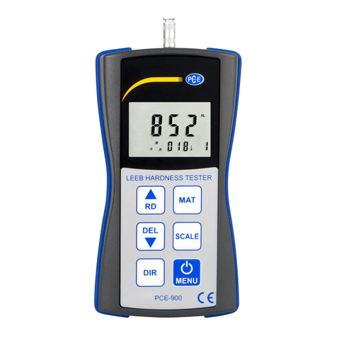
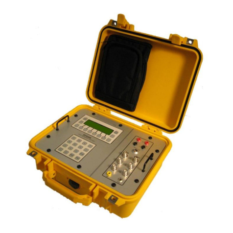
barfield 2548H Operator's manual

USER INSTRUCTION MANUAL
M/N: 2548H, P/N: 101-00420
Doc. P/N: 56-101-00420
Revision C
November 7, 2014
____________________________________
BARFIELD, INC.
Corporate Headquarters
4101 Northwest 29thStreet
Miami, Florida 33142
www.barfieldinc.com
Email: [email protected]
Copyright © 2014 Barfield Inc. All Rights Reserved.
2548H FUEL QUANTITY TEST SET

2548H INSTRUCTION MANUAL
56-101-00420 Rev. C Contact
Nov /07 /14 Page ii
CONTACT INFORMATION
Users are requested to notify the manufacturer of any discrepancy, omission, or error found in
this manual. Inquiries should include specific questions and reference the publication title,
number, chapter, page, figure, paragraph, and effective date.
Please send comments to:
TECHNICAL CUSTOMER SUPPORT - GSTE
BARFIELD, INC.
P.O. BOX 025367
MIAMI, FL 33102-5367
USA
Telephone (305) 894-5400
(800) 321-1039
Fax (305) 894-5401

2548H INSTRUCTION MANUAL
56-101-00420 Rev. C Attention
Nov /07 /14 Page iii
ATTENTION
Although every effort has been made to provide the end user of this equipment with the most
current and accurate information, it may be necessary to revise this manual in the future. Please
be sure to complete and return the enclosed OWNER WARRANTY REGISTRATION CARD to
Barfield in order to validate the warranty and to ensure that you will receive updated information
when published. You MUST have your name and address on file at Barfield as a registered
user of this equipment, to be able to obtain the service covered by the warranty.
Visit the company website, http://barfieldinc.com/, for publication updates.
Please send the Registration Card to:
Barfield, Inc.
P.O. Box 025367
Miami, FL 33102-5367
USA

2548H INSTRUCTION MANUAL
56-101-00420 Rev. C REV
Nov /07 /14 Page iv
REVISION RECORD
REV.
ECO #
REV. DATE
DESCRIPTION OF CHANGE
A
B
C
N/A
260-00729
260-01053
March 1, 2003
February 3, 2009
November 7, 2014
Initial Release. This manual supercedes
2548H-8005 Instruction manual and/or previously
released Instruction manuals for model 2548H.
Updated Company Information and logo. Page
numbering and format were reformatted.
Updated Barfield logo

2548H INSTRUCTION MANUAL
56-101-00420 Rev. C Maint.
Nov /07 /14 Page v
MAINTENANCE AND REPAIR INFORMATION
The manufacturer of this equipment does not recommend the user to attempt any maintenance
or repair. In case of malfunction, contact the manufacturer, to obtain the list of approved repair
facilities worldwide, ensuring that this equipment will be serviced using proper procedures and
certified instruments. A Return Maintenance Authorization (RMA) number will be assigned
during this call, to keep track of the shipment and the service.
BARFIELD PRODUCT SUPPORT
DIVISION
Shipping Address:
Telephone (305) 894-5400
(800) 321-1039
Fax (305) 894-5401
Barfield, Inc.
4101 NW 29th Street
Miami, Florida 33142
USA
Mailing Address:
Barfield, Inc.
4101 NW 29th Street
Miami, Florida 33142
USA

THIS PAGE INTENTIONALLY LEFT BLANK

2548H INSTRUCTION MANUAL
56-101-00420 Rev. C TOC
Nov /07 /14 Page vii
TABLE OF CONTENTS
Contact Information
Attention Page
Revision Record Page
Maintenance and Repair Information
Table of Contents
List of Figures
Page
INTRODUCTION
1. PUBLICATION BREAKDOWN ..............................................................................1
2. INFORMATION PROVIDED WITH THE UNIT......................................................1
3. RECERTIFICATION ...............................................................................................2
CHAPTER 1: GENERAL INFORMATION
1. PURPOSE ..............................................................................................................5
2. 2548H FRONT PANEL COMPONENTS...............................................................6
CHAPTER 2: SPECIFICATIONS AND CAPABILITIES
1. CAPABILITIES ................................................................................................. 9
2. SPECIFICATIONS........................................................................................... 9
3. PHYSICAL DATA .......................................................................................... 10
CHAPTER 3: OPERATION
1. GENERAL INFORMATION ........................................................................... 11
2. PRELIMINARY .............................................................................................. 13
3. PRECAUTIONS............................................................................................. 14
4. SYSTEM INSULATION TEST ....................................................................... 14
5. INDIVIDUAL TANK UNIT INSULATION TEST.............................................. 18
6. SYSTEM CAPACITANCE TEST ................................................................... 19
7. INDIVIDUAL TANK UNIT CAPACITANCE TEST.......................................... 21
8. AMPLIFIER TEST/CALIBRATION ................................................................ 22
9. SYSTEM CALIBRATION............................................................................... 26
CHAPTER 3: RECEIVING, SHIPPING, STORAGE
1. RECEIVING................................................................................................... 33
2. SHIPPING ..................................................................................................... 33
3. STORAGE..................................................................................................... 33

2548H INSTRUCTION MANUAL
56-101-00420 Rev. C LOF
Nov /07 /14 Page viii
LIST OF FIGURES
Page
Figure 1 Identification Label ................................................................................... 1
Figure 2 Owner Warranty Registration Card .......................................................... 2
Figure 3 Limited Warranty Statement Card............................................................ 3
Figure 4 2548H AC Fuel Quantity Test Set............................................................ 5
Figure 5 2548H Front Panel Components.............................................................. 6
Figure 6 Insulation Test, Configuration #1 ........................................................... 16
Figure 7 Insulation Test, Configuration #2 ........................................................... 16
Figure 8 Insulation Test, Configuration #3 ........................................................... 18
Figure 9 Insulation Test, Configuration #4 ........................................................... 18
Figure 10 Configuration of Capacitance Test......................................................... 19
Figure 11 Individual Tank Unit Capacitance Test, Configuration #1 ...................... 21
Figure 12 Individual Tank Unit Capacitance Test, Configuration #2 ...................... 21
Figure 13 Capacitance Simulation, Configuration #1............................................. 23
Figure 14 Capacitance Simulation, Configuration #2............................................. 23
Figure 15 Capacitance Simulation, Configuration #3............................................. 24
Figure 16 System Calibration (Method 1), Configuration #1 .................................. 27
Figure 17 System Calibration (Method 1), Configuration #2 .................................. 27
Figure 18 System Calibration (Method 1), Configuration #3 .................................. 28

2548H INSTRUCTION MANUAL
56-101-00420 Rev. C Intro
Nov /07 /14 Page 1 of 33
INTRODUCTION
1. PUBLICATION BREAKDOWN
This instruction manual establishes the operation standards for the 2548H Fuel Quantity
Test Set
Its purpose is to provide sufficient information for the personnel unfamiliar with this unit to
understand this equipment, identify its parts, and operate it in accordance with proper
procedures, operating techniques, precautions and limitations.
2. INFORMATION PROVIDED WITH THE UNIT
Besides this User Instruction Manual, the 2548H Test Set is provided with the four items
described below.
A. An identification label similar to Figure 1 and located on the front bulkhead of the Test
Set, provides the following information:
Manufacturer Name
Designation of Equipment
Equipment Part Number
Equipment Model Number Equipment Serial Number
Equipment Modification (if applicable) Equipment Options (if applicable)
Figure 1 IDENTIFICATION LABEL
FUEL QUANTITY T/S
101-00420
2548H

2548H INSTRUCTION MANUAL
56-101-00420 Rev. C Intro
Nov /07 /14 Page 2 of 33
B. The Owner's Warranty Registration card, (Figure 2), which is to be completed by the
owner and returned to the Barfield within ten (10) days of purchase to insure validation
of the warranty.
Figure 2 OWNER WARRANTY REGISTRATION CARD
C. The Limited Warranty Statement, (Figure 3), which lists the manufacturer's obligation to
the original purchaser.
D. Each new or re-certified unit is delivered with a Certificate that shows the date when the
unit was tested by the manufacturer, its serial number, and when the next certification is
due. This certificate confirms that the unit performed according to its design
specifications.
3. RECERTIFICATION
The Test Set P/N 101-00420 has a one-year recertification requirement. Maintenance
required by this unit must be performed by qualified technicians in a shop equipped with the
necessary tooling and facilities.

2548H INSTRUCTION MANUAL
56-101-00420 Rev. C Intro
Nov /07 /14 Page 3 of 33
Figure 3 LIMITED WARRANTY STATEMENT

THIS PAGE INTENTIONALLY LEFT BLANK

2548H INSTRUCTION MANUAL
56-101-00420 Rev. C Ch. 1
Nov /07 /14 Page 5 of 33
CHAPTER 1: DESCRIPTION
1. PURPOSE
The Barfield 2548H Fuel Quantity Test Set (P/N 101-00420) is specifically designed to
satisfy the need to service guarded, capacitance-type aircraft fuel and oil quantity-measuring
systems. Accuracy and reliability have been optimized together with portability and
convenience. The accuracy of the Test Set (T/S) ensures that manufacturer’s measurement
and calibration requirements are met. The potentials and currents the T/S introduces are
limited to meet all safety precautions. The Test Set’s circuitry components also provide
current limiting in case of a catastrophic failure. Three measurements and two capacitance
simulator functions are provided through the function selector switch.
The standard lead package enclosed with the 2548H Test Set provides all accessories
necessary (except adapter cables) to adapt the adapter cable, aircraft or component to the
Test Set. Please refer to the Barfield Ground Test Equipment catalog for further
information.
Figure 4 2548H FUEL QUANTITY TEST SET
A. Adapter Cables
Each individual Aircraft Fuel Quantity System requires its own particular adapter cable(s)
and the specific instructions. Adapter Cable configurations and interfaces vary widely to
accommodate the variety of fuel systems. There is an extensive selection of adapter
cables manufactured by Barfield Inc. to be used with the 2548H Fuel Quantity Test Set.
Please contact the Barfield Ground Support Test Equipment Sales department or visit
the Barfield website at http://www.barfieldinc.com/ground.html for further information.

2548H INSTRUCTION MANUAL
56-101-00420 Rev. C Ch. 1
Nov /07 /14 Page 6 of 33
B. Carrying Case
The carrying case is made of drawn aluminum for maximum strength. The lid is fitted
with a bracket, which, when closed, contacts the ON/OFF switch if it was left in the ON
position, and moves it to the OFF position.
2. 2548H FRONT PANEL COMPONENTS
Note: Refer to Figure 5 for item number identification.
Figure 5 2548H PANEL COMPONENTS
(1) The PRESS TO MEASURE is a pushbutton, which when pressed, activates the bridge
VCC supply and switches the bridge for external use.
(2) The GND banana jack provides a connection to the Test Set’s case ground.
(3) The LO-Z is a polarized BNC receptacle for the LO-Z insulation leak tests.
(4) The HI-Z is a polarized BNC receptacle for the HI-Z insulation leak tests.

2548H INSTRUCTION MANUAL
56-101-00420 Rev. C Ch. 1
Nov /07 /14 Page 7 of 33
(5) TEST FUNCTION is a rotary switch, which selects one (1) of five (5) test functions.
When the Test Set is placed in the CAP SIM 1 or CAP SIM 2 function, the meter may
be substituted for a DC meter-type fuel quantity indicator.
(6) INS TEST POINTS selector switch permits selection of one (1) of six (6) pairs of
different test points for insulation leak tests.
(6A) RANGE selects x1 or x.01 MΩfor display during insulation tests.
(7) The INDICATOR banana jacks are used for indicator input connections for 0-1100 µA
meter testing or substitution.
(8) METER ADJUST is a linear potentiometer, which controls the 0-1100 µA test current
or adjusts the megaohmmeter for infinity (∞), full scale setting. When the INDICATOR
switch is selected, this component provides an adjustable current through the panel
meter to the indicator jacks.
(9) The PANEL METER is a DC taut-band micro ammeter, which provides the 0-1100 µA
current scale, 0-5000 MΩscale and battery condition scale. Its circuitry components
allow adjustments for all test functions from full scale to 1100 µA.
(10) The BATTERY COMPARTMENT contains the batteries or the optional AC power
supply. The four (4) 9V batteries are connected to provide a bipolar 18 VDC supply
that is controlled through the ON/OFF switch. The optional 115 VAC or 230 VAC
power supply assembly is interchangeable with the DC battery supply assembly. The
AC supply is short-circuit protected and warranted by the manufacturer.
(11) ON/OFF is a toggle switch that provides the output battery or AC power supply.
(12) BATT TEST is a pushbutton, which when pressed, connects the panel meter as a full-
scale meter 0-37.4 voltmeter across the battery supply. (The BATT OK measurement
line indicates 24.8V.)
(13) TANK CAP pF thumbwheel assembly selects the capacitance simulator value
between HI-Z COAX and LO-Z TANK jacks or bridge value.
(14) HI-Z COAX, a BNC receptacle, provides a HI-Z connection for the bridge and the
simulators.
(15) LO-Z TANK, a polarized BNC receptacle provides a LO-Z connection for the bridge
and the tank simulators.
(16) LO-Z COMP is a polarized BNC receptacle connection for the compensator simulator.
(17) COMP SIM pF is a 100’s-10’s thumbwheel assembly and a 0-10 pF variable for setting
compensator capacitance between HI-Z COAX and LO-Z COMP.
(18) The COMP CAL is a pushbutton which, when pressed, connects the compensator
simulator to the capacitance bridge.

THIS PAGE INTENTIONALLY LEFT BLANK

2548H INSTRUCTION MANUAL
56-101-00420 Rev. C Ch. 2
Nov /07 /14 Page 9 of 33
CHAPTER 2: CAPABILITIES AND SPECIFICATIONS
1. CAPABILITIES
When the 2548H Fuel Quantity T/S is connected through the appropriate adapter cables,
the following functions may be performed:
Measure capacitance of individual or interconnected tank sensor probes or probe
simulators
Measure the insulation resistance of system wiring, probes, or other discrete test points.
Test the performance of indicators and signal conditioners or bridge amplifiers.
Simulate capacitances representative of empty or full probes or systems, or the added
capacitance effect of the fuel between empty and full.
Substitute the test set meter for DC meter-movement type gauges, and provides
adjustable metered current to test these gauges.
2. SPECIFICATIONS
INSULATION
Range: 0 to Infinity (∞) in two scales:
5 to 5000 MΩ
50 kΩto 50 MΩ
Accuracy: ±5% of reading nominal, but not in excess of ±2% of scale length all
through range
Applied Voltage: 10 VDC nominal
Current 50 nA maximum
INDICATOR
Range: 0-1100 µA in 10 µA increments
Accuracy: ±1% of full scale
CAPACITANCE BRIDGE
Range: 0 to 999.9 pF in 0.1 pF increments
Accuracy: ± (0.1% of reading + 0.1 pF)
Signal: 400 Hz at 5.7 V RMS nominal

2548H INSTRUCTION MANUAL
56-101-00420 Rev. C Ch. 2
Nov /07 /14 Page 10 of 33
2. SPECIFICATIONS (continued)
CAPACITANCE SIMULATORS
Tank Range: 0 to 999.9 pF in 0.1 pF increments
Accuracy: Same as Capacitance Bridge
COMP Range: 10-400 pF continuously adjustable
Accuracy: Set with Capacitance Bridge
Maximum Input 75 V RMS, 220 V peak-to-peak (above 3 kHz, Tank Simulator limit
decreases proportionately to 10 V RMS at 25 kHz)
INPUT POWER
Batteries Four (4) Each, 9V Batteries
External Power 115V or 230V
50-400 Hz AC Optional
3. PHYSICAL DATA
In. Cm.
Height 5.3 13.5
Width 12.2 31.0
Depth 10.4 26.4
Lbs. Kg
Weight 7.0 3.2

2548H INSTRUCTION MANUAL
56-101-00420 Rev. C Ch. 3
Nov /07 /14 Page 11 of 33
CHAPTER 3: OPERATION
1. GENERAL INFORMATION
Fuel Quantity Indicating Systems provide the crew with an accurate display of the remaining
fuel. The quantity of fuel shows on the fuel quantity indicator(s) in the flight compartment.
The Fuel Quantity Indicating System includes the amplifier or signal conditioners (also
known as the amplifiers) and the probe(s)/transmitter(s) that are installed in each tank (also
knows as the Tank Unit). A Tank Unit is a capacitor. It consists of two (2) conductive tubes
separated by an air gap, or a combination of air and fuel. The Unit is connected to terminals
that are, in turn, connected to the amplifier. This unit measures the fuel mass or weight.
The volume or weight is determined by the dielectric constant of the insulating air or fuel, or
air/fuel mixture in the tank; then, fed to other units for refinement or amplification before
being displayed on the indicator.
Note: For more complete and detailed information on specific Fuel Quantity Systems, refer
to the appropriate Aircraft/System Maintenance Manuals.
A. Stray Capacitance Compensation
A certain amount of stray capacitances exists within the Test Set (T/S). This could be
caused by exposure of unshielded lead wire at connecting points or capacitance
between switch contacts and between any HI-Z to LO-Z conductors (which cannot be
effectively shielded from one another.
These stray capacitances change from one function to another due to the addition or
subtraction of circuitry and, due to the differences in the mechanical position of movable
contact switches. A mounted circuit on the meter PC board compensates these stray
capacitances. To ensure accurate results, adapter harness stray capacitances should
be subtracted from the measured values and calibration settings.

2548H INSTRUCTION MANUAL
56-101-00420 Rev. C Ch. 3
Nov /07 /14 Page 12 of 33
B. Methods of Calibration
There are two (2) methods of Fuel Quantity System calibration:
Method 1:Dry Tank (PREFERRED)
Method 2:Wet Tank (ALTERNATE)
(1) Method 1 (Preferred)
The Dry Tank method of calibration is done without fuel in the tank(s) and with
the Tank Unit(s) dry. A capacitance value is substituted for an equivalent amount
of fuel (full) in the tanks. The indicator is then adjusted to display this full level of
fuel. (This method is more accurate since the indicator’s zero (0/ ) indication is set
to the actual empty tank value thus ensuring the integrity of the system’s empty
level.)
(2) Method 2 (Alternate)
The Wet Tank method of calibration is done with fuel in the tanks. The Tank Unit
is “electrically” removed from the Fuel Quantity Indicating System. Simulated
values for both EMPTY and FULL adjustments are made to the indicator. The
actual empty setting is questionable. Accuracy is sacrificed by using simulated
values.
However, if correct, current dry tank capacitance values are available for the
aircraft by serial number, these values should be used for the indicator EMPTY
adjustment. The user may than add the ADD FOR FULL value to the current dry
tank value to get the FULL adjustment value. (Refer to the Aircraft Maintenance
manual.)
Note: Method 2 should be used only as a TEMPORARY measure. Method 1
should then be done at a more suitable time.
Other manuals for 2548H
1
This manual suits for next models
1
Table of contents
Other barfield Test Equipment manuals
barfield
barfield DPS400 User manual
barfield
barfield TT-1000A Operator's manual
barfield
barfield 1811D Series Operator's manual

barfield
barfield DPS1000 Operator's manual
barfield
barfield 2311FA Operator's manual
barfield
barfield DPS1000 Operator's manual
barfield
barfield 1811GA Series Operator's manual
barfield
barfield 1811NG Operator's manual
barfield
barfield TT-1000A Operator's manual
barfield
barfield DFQ40K Operator's manual

