Cutler-Hammer HWT-500 User manual

I.B. 35-557
1 of 45
Instructions for
Cutler-Hammer Type HWT-500
Network Protector
Portable Test Set
READ AND UNDERSTAND THESE INSTRUCTIONS BEFORE ATTEMPTING
ANY MAINTENANCE OF THE NETWORK PROTECTOR
SEE IMPORTANT DISCLAIMER OF WARRANTIES AND LIMITATION OF LIABILITY ON
NEXT PAGE
Cutler-Hammer
2210 Highway 72/221 East
Greenwood SC 29649
Effective July, 2001

I.B. 35-557
2 of 45
DISCLAIMER OF WARRANTIES
AND LIMITATION OF LIABILITY
THERE ARE NO UNDERSTANDINGS, AGREEMENTS, REPRESENTATIONS OR
WARRANTIES, EXPRESSED OR IMPLIED, INCLUDING WARRANTIES OF
MERCHANTABILITY OR FITNESS FOR A PARTICULAR PURPOSE, OTHER THAN
THOSE SPECIFICALLY SET OUT BY AN EXISTING CONTRACT BETWEEN THE
PARTIES. ANY SUCH CONTRACT STATES THE ENTIRE OBLIGATION OF SELLER.
THE CONTENTS OF THIS DOCUMENT SHALL NOT BECOME PART OF OR MODIFY
ANY PRIOR OR EXISTING AGREEMENT, COMMITMENT OR RELATIONSHIP.
The information, recommendations, descriptions and safety notifications in this
document are based on Cutler-Hammer’s experience and judgement with respect to
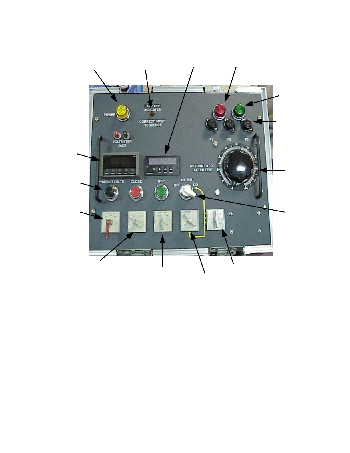
the HWT-500 TEST SET. THIS INFORMATION SHOULD NOT BE CONSIDERED TO BE
ALL-INCLUSIVE OR COVERING ALL CONTINGENCIES. If further information is
required, Cutler-Hammer should be consulted.
NO WARRANTIES, EXPRESSED OR IMPLIED, INCLUDING WARRANTIES OF
FITNESS FOR A PARTICULAR PURPOSE OR MERCHANTABILITY, OR WARRANTIES
ARISING FROM COURSE OF DEALING OR USAGE OF TRADE, ARE MADE
REGARDING THE INFORMATION, RECOMMENDATIONS, DESCRIPTIONS AND
SAFETY NOTATIONS CONTAINED HEREIN. In no event will Cutler-Hammer be
responsible to the user in contract, in tort (including negligence), strict liability or
otherwise for any special, indirect, incidental or consequential damage or loss
whatsoever including but not limited to damage to or loss of use of equipment, plant
or power system, cost of capital, loss of profits or revenues, cost of replacement
power, additional expenses in the use of existing power facilities, or claims against
the user by its customers resulting from the use of the information,
recommendations, descriptions and safety notations contained herein.
Please read instruction book I.B. 35-557 carefully before attempting to use the HWT-500.
Any questions regarding the HWT-500 Test Set or its instruction booklet may be answered by calling the
Cutler-Hammer Network Protector toll-free number: 1-800-525-6821.
Failure to follow instructions contained within the instruction booklet and addendum could result in severe
personal injury, death, and/or product or property damage and will void any warranties, expressed or implied.
These instructions do not purport to cover all possible contingencies that may arise during
installation, operation, or maintenance, and all details and variations of this equipment. If further
information is desired by purchaser regarding his particular installation, operation or maintenance of
his equipment, the local Cutler-Hammer representative should be contacted.

I.B. 35-557
3 of 45
Table of Contents Page Page
Introduction…………………………………… 4 GENERAL ELECTRIC
Safety Information…………………………… 5
Test Set Transportation……………………… 6 Individual Relay Test…………………… 28
General Operating Information……………… 7 CAN or CHN Master Relay Overvoltage
Close Test…………………………………
29
Control Panel Layout………………………… 8 CAN or CHN Master Relay Reverse
Current Trip Test…………………………
30
Overall Operational Test……………………… 12 PYC16 Delayed-Sensitive Trip Test…… 31
Overall Close and Trip………………………… 14 CAL or CHL Phasing Relay Overvoltage
Close Test…………………………………
32
SSNPR Close Test……………………… 33
WESTINGHOUSE SSNPR Trip Test………………………… 34
SSNPR Phase Detection Test………… 34
Individual Relay Test………………………… 16 Mechanism Components Test………… 36
CN-33 Master Relay Overvoltage Test…… 16 HWT-500 Maintenance and Repair…… 38
CN-33 Master Relay Reverse Current Trip
Test………………………………………………
17
Table 1 - Suggested Relay Settings…… 39
CN-33 Single Phase Reverse Current Trip
Test………………………………………………
19
Table 2 - Renewal Parts………………… 41
CNJ Phasing Relay Overvoltage Test……… 20
BN De-sensitizing Relay Time Delay Test..… 21
BN De-sensitizing Relay Instantaneous Trip
Test………………………………………………
22
Mechanism Component Test………………… 23
MPCR Solid State Relay Close Test………… 26
MPCR Solid State Relay Trip Test………… 27
MPCR Solid State Relay Phase Detection
Test………………………………………………
27

I.B. 35-557
4 of 45
INTRODUCTION
The Cutler-Hammer type HWT-500 universal, portable network protector test set has been
designed for use on network protector breakers of all amperage ratings, 60HZ, and in the
voltage class of 480 and 216.
It is designed for electrical and mechanical testing of any network protector breaker, or
selected component parts, on voltages from 208Y/120 to 480Y/277 volts, three phase, four
wire wye connected systems, or 480 volt, three phase, three wire delta systems.
The primary purpose of this test set is for routine testing of network protector breakers and
calibration of network relays and electrical components in the field. However, if a network
protector or a simulated network protector breaker is used with this test set, scales of the
digital meters on the test set are such that network relays can be calibrated at a service
center or laboratory.
NOTE
VOLTAGES AT SERVICE CENTERS OR LABORATORIES MAY NOT BE EQUIVALENT IN
VOLTAGE MAGNITUDE OR VOLTAGE BALANCE BETWEEN PHASES AS COMPARED TO
THE VOLTAGES FOUND IN MOST NETWORK LOCATIONS. MOST ELECTRO-MECHANICAL
RELAYS ARE VOLTAGE SENSITIVE DEVICES WHOSE CALIBRATED SETTINGS CAN BE
AFFECTED BY VARIOUS SYSTEM VOLTAGE LEVELS. DUE TO THIS FACT, WE
STRONGLY RECOMMEND THAT THE FINAL RELAY CALIBRATION OF ELECTRO-
MECHANICAL RELAYS BE PERFORMED USING THE SYSTEM VOLTAGE AVAILABLE AT
EACH NETWORK PROTECTOR LOCATION. HOWEVER, SOLID STATE RELAYS ARE
TYPICALLY NOT AFFECTED BY VOLTAGE FLUCTUATION AND ARE WELL SUITED FOR
LABORATORY CALIBRATIONS.

I.B. 35-557
5 of 45
SAFETY INFORMATION
WARNING
1. FAILURE TO FOLLOW INSTRUCTIONS CONTAINED HEREIN COULD RESULT IN
SEVERE PERSONAL INJURY, DEATH, AND/OR PRODUCT OR PROPERTY
DAMAGE.
2. ANY MECHANICAL OR ELECTRICAL MODIFICATION TO ANY NETWORK ROTECTOR
REQUIRES THAT THE NETWORK PROTECTOR BE GIVEN APPROPRIATE ELECTRICAL
TESTS, USING PROPERLY MAINTAINED TESTING DEVICES, BEFORE PLACING INTO
SERVICE. FAILURE TO PERFORM SUCH ELECTRICAL TESTS CREATES CONDITIONS
LEADING TO THE POSSIBILITY OF DEATH, SEVERE PERSONAL INJURY AND/OR
PROPERTY DAMAGE.
Keep this Instruction Book available to those responsible for the maintenance and operation of
network protectors. It should be consulted before any procedures are performed.
The installation, testing and maintenance of a network protector present numerous potential
unsafe conditions, including but not limited to, the following:
• Improper Operation
• Lethal Voltages
• Moving Parts
• Heavy Components
Specialized procedures and instructions are required and must be adhered to when working on
such apparatus.
WARNING
AFTER THE TEST SET HAS BEEN COMPLETELY CONNECTED AND IS IN OPERATION,
POTENTIALLY LETHAL VOLTAGES ARE PRESENT WITHIN THE NETWORK PROTECTOR
BREAKER AND WIRING HARNESS OF THE UNIT UNDER TEST. ENERGIZED
COMPONENTS ARE NOW EXPOSED.
PRIOR TO ENERGIZING THE NETWORK PROTECTOR BREAKER THROUGH THE TEST
SET, THE OPERATOR MUST MAKE CERTAIN THAT OTHER PERSONNEL IN THE AREA
MOVE A SAFE DISTANCE AWAY FROM THE UNIT UNDER TEST. FAILURE TO FOLLOW
THESE WARNINGS MAY RESULT IN DEATH, SEVERE PERSONAL INJURY AND/OR
PROPERTY DAMAGE.
BEFORE CONNECTING OR DISCONNECTING ANY OF THE TEST SET LEADS FROM THE
BREAKER OR THE SUPPLY, MAKE CERTAIN THAT THE TEST SET RED SUPPLY SWITCH
IS IN THE “OFF” POSITION.

I.B. 35-557
6 of 45
TEST SET TRANSPORTATION
The HWT-500 test set is equipped with wheels and a retractable handle assembly to assist in the
transportation of the device.
To extend the handle, slide the red handle lock located underneath retracted handle and extend
the handle assembly outward.
End handles with spring returns are supplied on the main body of the unit. When lowering the
HWT-500 into an underground vault, make certain that the rope or sling is attached to the main
body end handle which is located on the same side as the retractable handle assembly. This
keeps the wheels on the bottom end of the unit and aids in the balance of the unit when it comes
to rest on the floor of the vault.
Likewise, when manually lifting the unit, always use the main body end handles.
DANGER
DO NOT ATTEMPT TO LOWER THE HWT-500 BY ATTACHING SLINGS OR ROPES TO
THE RETRACTABLE HANDLE ASSEMBLY. TO DO SO MAY CAUSE THE
RETRACTABLE HANDLE ASSEMBLY TO PERMANENTLY DISENGAGE RESULTING
IN DEATH, SEVERE PERSONAL INJURY AND/OR PROPERTY DAMAGE.
USE ONLY THE END HANDLE OF THE MAIN BODY OF THE UNIT LOCATED ON THE
SAME END AS THE RETRACTABLE HANDLE ASSEMBLY.
The test set cover is secured to the main body of the unit with four over-toggle suitcase
latches.
To return the handle into the case, slide the red handle lock and push the retractable
handle into the body of the case.

I.B. 35-557
7 of 45
GENERAL OPERATING INFORMATION
WARNING
ANY MECHANICAL OR ELECTRICAL MODIFICATION TO ANY NETWORK PROTECTOR
REQUIRES THAT THE NETWORK PROTECTOR BE GIVEN APPROPRIATE ELECTRICAL
TESTS, USING PROPERLY MAINTAINED TESTING DEVICES, BEFORE PLACING INTO
SERVICE. FAILURE TO PERFORM SUCH ELECTRICAL TESTS CREATES CONDITIONS
LEADING TO THE POSSIBILITY OF DEATH, SEVERE PERSONAL INJURY AND/OR
PROPERTY DAMAGE.
1. The Type HWT-500 test set is equipped with selector switches and controls to vary both the
overvoltage phasing value as well as the reverse current magnitude at various preselected
angles. Refer to pages 8-10 regarding the control panel layout and description of the controls.
2. The HWT-500 is equipped with a single lamp PHASE SEQUENCE indicator that becomes
energized when the supply cables are attached to an energized voltage source, and the supply
switch is at the 216 or 480V. This permits immediate verification of the correct sequence. An
illuminated lamp indicates that the system sequence is incorrect. Periodically check the lamp by
purposely connecting the input supply leads incorrectly.
3. An electrical interlock is built into the HWT-500 that prevents the possibility of 480 volts entering
the test set when the SUPPLY switch is in the 216 position. Moving the red SUPPLY switch to
the 216 position when 480 volt potential is present at the supply leads of the test set will result in
the electrical shutdown of the test set.
4. The position of the SUPPLY switch (480 or 216) refers to the system voltage of the network
protector being tested. The 216 position is to be used with network voltages up to 216 volts that
are either wye or delta connected. The 480 position is to be used with network voltages of 480
volts that are either wye or delta connected. A protector used on 480-volt systems may or may
not utilize 480-volt class relays. Regardless of the fact, all 480-volt network protectors are to be
tested with the red SUPPLY switch in the 480 position.
CAUTION
ON DELTA SYSTEMS THE TEST SET LEADS MARKED NEUTRAL MUST BE CONNECTED TO
AN EARTH GROUND FOR CORRECT OPERATION OF TEST SET CIRCUITS. ON WYE
CONNECTED SYSTEMS BOTH THE NETWORK PROTECTOR ENCLOSURE AND THE
NETWORK PROTECTOR BREAKER MUST BE GROUNDED.
5. Before any testing shall commence, the network protector breaker must be in the disconnected
and rolled out position, with the main breaker contacts in the OPEN position. Proceed to
connect the test control cables to the test set and to the network protector.
Insure that the SUPPLY switch is placed in the “OFF” position. Connect the SUPPLY LEADS to the
source voltage. Check that the PHASE SEQUENCE indicator light is “OFF” indicating that the
sequence input is correct. Using the SUPPLY VM switch, a check of the input supply voltages
should be made to insure that the input supply is balanced, both phase-to-phase and phase-to-
ground.
6. The HWT-500 controls the phasing volts and reverse current through the use of the three phase
VARIAC.

I.B. 35-557
8 of 45
Power
Light
Sequence
Light
Ammeter Red Indicating
Light
Voltmete
Phasing Volt
Switch
Supply Voltmeter
Switch
Function
Phasing
Switch
I&PV Switch (Current &
Phasing)
KTKR-15 Fuse
Holders
Green Indicating
Light
Single Phase
Switch
Variac
Supply

I.B. 35-557
9 of 45
DANGER
IT IS VERY IMPORTANT TO RETURN THE VARIAC TO “0” AFTER THE COMPLETION OF
EACH OPERATION. FAILURE TO FOLLOW THIS WARNING WILL RESULT IN DAMAGE TO
VARIAC INSULATION.
P1 and P2 Cable Assemblies

I.B. 35-557
10 of 45
DESCRIPTION OF CONTROLS
P1 and P2 – Cable Input Sockets
NOTE – They are polarized and have a different contact arrangement. Dust covers with lanyards
are supplied.
F1, F2, F3 – Test kit fuses, Type KTKR-15.
POWER ON LIGHT – Is illuminated when the supply switch is moved from the “OFF” position to
either the 480 or 216 position.
SUPPLY SWITCH – Marked “216-OFF-480”, should be moved only after all the cable connections
are complete and set to the correct system voltage at the time of testing.
AMMETER – This digital meter shows the reverse current trip value.
VOLTMETER – The digital voltmeter reads system voltage determined by the position of the Supply
Voltmeter Switch. It also reads phasing volts if the phasing volt selector switch is in the ON position
and the I & PV switch is in any one of the PV (A, B, C) selections. NOTE – both digital meters,
upon power-up, go through an initializing sequence that can take several seconds to complete.
The red and green indicator lights are used in conjunction with the “COMM-RED-GREEN” marked
leads. These are intended to be used with dry contacts.
WARNING
DO NOT USE THE LEADS MARKED “COMM-RED-GREEN” ON ENERGIZED CIRCUITS.
PHASING SWITCH – determines the phasing voltage phasor angle with respect to the network
voltage in the “0” and “60” degree position. It also determines the reverse current angle with
respect to the individual phase voltage at either “120”, “180” or “240” degree position.
TEST SWITCH – Relay position is used to test and calibrate network protectors with relays. The
Mech position is used in the mechanical test without relays.
SUPPLY VOLT SWITCH – will monitor the system voltage. It is also used in the mechanical mode
to select either phase-to-phase or phase-to-ground connections.
VARIAC – is used to set the various voltages either phase-to-phase or phase-to-ground during both
mechanical testing and voltage as well as current in the Relay mode.
PHASING VOLT SWITCH – in the ON position permits phasing volts to be displayed on the
voltmeter. In the OFF position will display the system voltage determined by the Supply
Voltmeter Switch position. It should be in the OFF position for all MECH tests.

I.B. 35-557
11 of 45
Output Cable Assemblies
30 Foot Cable Assembly for Socket P2
A-B-C…………………………………………………Supply leads with in-line KTKR-30 fuses
* COMM-RED-GREEN…………………………………Red and Green indicating lamp leads
COMM-CLOSE-TRIP……………………………………………………Mechanical Test leads
N (GRD)…………………………………………………………Housing neutral or ground lead
30 Foot Cable Assembly for Socket P1
NA-NB-NC……………………………………………………………Network side breaker leads
TA-TB-TC…………………………………………………………Transformer side breaker leads
N (GRD)……………………………………………………………Breaker neutral or ground lead
WARNING
DO NOT USE THE LEADS MARKED “COMM-RED-GREEN” ON ENERGIZED CIRCUITS.

I.B. 35-557
12 of 45
PROCEDURE FOR OVERALL OPERATIONAL TEST
Before commencing work, refer to Safety Information.
Using Cutler-Hammer Type HWT-500 test Set on a 216Y/125 volt, 3 phase, 4-wire system with
solid state relays. Refer to figure on page 14 for the required test lead connections.
This test will determine if the network protector, as a whole, is operating correctly. The test consists
of two parts; an overall close test and an overall tripping test.
1. Roll the removable breaker out of its enclosure to the test and inspection position.
CAUTION
REFER TO THE PROPER INSTRUCTION BOOK FOR THE NETWORK PROTECTOR UNDER
TEST FOR THE CORRECT PROCEDURE TO DE-ENERGIZE AND ROLL THE REMOVABLE
BREAKER OUT TO ITS TEST AND INSPECTION POSITION.
2. Attach test cable P1 and P2 to the test set.
3. Inspect and check that the SUPPLY switch is in the “OFF” position and that the VARIAC is
turned to the “OFF” position.
4. Connect the Network side test leads to the removable breaker. These leads are marked NA,
NB, and NC.
5. Connect the Transformer side test leads to the removable breaker. These leads are marked
TA, TB, and TC.
6. Connect the Neutral (ground) lead to a ground point on the rollout unit.
7. Connect the Neutral (ground) lead to a suitable grounding point inside the network protector
enclosure.
8. While wearing electrical insulating gloves, connect the test set SUPPLY LEADS to the network
side terminals inside the protector enclosure.
9. Set the removable breaker to the automatic position.
10. Place the Relay Type Switch in the “RELAY” mode.
11. Place the I & PV Switch in any one of the PV (A, B, or C) positions.
12. Place the Phasing Switch to the 0 degree position.
13. Place the Supply Switch to the “216” position.
14. Inspect that the Power light is illuminated and that both the Ammeter and Voltmeter are
functioning.
15. Inspect the Phase Sequence Indicating Light and ensure that it is NOT illuminated.

I.B. 35-557
13 of 45
16. Rotate the Supply Voltmeter switch checking all phase-to-phase and phase-to-ground voltages.
Return the Supply Voltmeter to the CA position.
17. Rotate the Phasing Volts Switch to the “ON” position.
18. Confirm that the breaker main contacts are open.
19. Turn the VARIAC knob clockwise to slowly increase the phasing volts. When the protector
closes observe the value of the phasing volts and return the VARIAC to the zero position.
NOTE: The voltmeter requires some time to adjust to lower voltage inputs. Please adjust
the voltmeter slowly when measuring small values of phasing volts. You will also note that
because of residual non-zero voltage across the VARIAC the voltmeter does not register
true zero volts.
20. With the protector closed you are now ready to perform a reverse current trip test.
21. Rotate the Phasing Volt switch counterclockwise to its “OFF” position.
22. Place the Phasing Switch to the 180-degree position.
23. Place the I & PV Switch to any one of AI, BI or CI positions.
24. Turn the VARIAC knob clockwise to slowly increase the reverse current. When the protector
trips observe the value of the trip current on the Ammeter and return the VARIAC to the zero
position.
25. If the network protector relay is found to be within your specified calibration you can proceed to
the Mechanical Component Test (Cutler-Hammer on page 23, General Electric on page 36).
The mechanical tests are performed to ensure that the motor, tripping device and intermediate
motor control device are operating at the minimum pick-up voltages.
NOTE: Because of the ruggedness of the HWT-500 design and the components selected, it
is possible to perform crossed phase, rolled phase and shorted phase tests using this
device so long as the breaker main contacts are in the open position and motor closing has
been blocked. Unintentional closures under these conditions will clear the 15 amp fuses
located on the front panel of the test set.
NOTE: The electrical interlock produces a noticeable hum in the 216 volt position and
is a normal condition of operation.

I.B. 35-557
14 of 45
OVERALL CLOSE AND TRIP TEST CONNECTION
Before commencing work, refer to the Safety Information.
Close Test – Switch positions
Network protector open and set for automatic operation
FUNCTION Switch – “RELAY” position
I & PV Switch – PVA position Supp VM Switch – CA position
PHASE switch – 60 position Single PH Test Switch – OFF position
PHASING volt switch – ON position VARIAC – zero position
SUPPLY Switch – 216 or 480 position depending on network system voltage
By increasing the VARIAC'S position, you can increase the overvoltage phasing value to the
desired value or to that value at which the network protector breaker will close its main
contacts. The network protector breaker should be closed several times to ensure that the
operation is consistent.

I.B. 35-557
15 of 45
Trip Test – Switch positions
Network protector closed and set for automatic operation
FUNCTION Switch – “RELAY” position
I & PV Switch – AI position Supp VM Switch – CA position
PHASE switch – 180 position Single PH Test Switch – OFF position
SUPPLY Switch – 216 or 480 position depending on network system voltage
VARIAC – zero position
By increasing the VARIAC'S position, you can increase the reverse current value to the
desired value or to that value at which the network protector breaker will open its main
contacts. The network protector breaker should be tripped several times to ensure that the
operation is consistent.
When making the overall tripping test on a network protector breaker equipped with an
electro-mechanical de-sensitizing relay, connections to the test set, network protector
breaker, and power source as well as the switch positions remain the same. The reverse
current is slowly increased from zero until the relay trip contact makes. This is the reverse
current required to trip the breaker. As soon as the master relay trip contact makes, the
timing cycle of the time delay relay begins and the timing cycle is completed when the
breaker trips.
NOTE: When using the Type MPC series of solid state relays having a time delay setting,
the reverse current should be adjusted somewhat higher than its setting to ensure that the
trip logic is initiated. Timing should begin after the trip set point has been exceeded on the
Ammeter.

I.B. 35-557
16 of 45
INDIVIDUAL RELAY TEST
Westinghouse Electro-Mechanical Type CN-33, CNJ, BN. Before commencing work, refer
to the Safety Information.
These tests determine if the relays on a network protector breaker, CN-33 master relay, CNJ
phasing relay and the BN de-sensitizing relay are functioning properly and their setting in
regard to overvoltage close, reverse current trip, time delay and instantaneous trip, is
correct.
The test lead connection to the network relay terminals are made by backing out the
terminal screws which correspond to the relay contact structure until the second machined
head appears. This will permit the attachment of one of the alligator clip leads marked
“COMM-RED-GREEN” to the exposed end of the terminal screw. In the case of the type BN
relay, the front steel cover of the relay must be removed before the relay terminal screws are
accessible. When the relay terminal screw is backed out, the contact between the relay
terminal screw and the network protector breaker wiring is broken, but the contact between
the relay terminal screw and the internal wiring of the relay continues to remain intact.
Switch Positions
Network Protector open, breaker does not have to be in automatic mode.
FUNCTION Switch – “RELAY” position I & PV Switch – PVA position
Supp VM Switch – CA position PHASE switch – 0 position
Single PH Test Switch – OFF position PHASING volt switch-ON position
SUPPLY Switch – 216 or 480 position depending on network system voltage
VARIAC – zero position
By increasing the VARIAC’S position, you can increase the in phase (zero degrees) overvoltage
phasing value to the desired overvoltage close value. The CN-33 relay overvoltage setting may be
adjusted through the use of a narrow blade screwdriver inserted in the overvoltage adjustment screw
located to the left side of the front bearing. Adjustment should be made until the red indicator light is
illuminated.
When making the CN-33 relay overvoltage close test on a 216-volt relay being used on a 480 volts
system the phasing voltage necessary to close the relay is not directly indicated on the Voltmeter.
The relay calibration on this system is determined by dividing the voltmeter reading by 2.2. However,
the suggested settings as listed in this manual are those that would be directly indicated by the
voltmeter.
The overvoltage setting of a CN-33 master relay must be made first since it is made by means of a
spiral spring fastened to the moving contact of the relay and will therefore affect the reverse current
setting of the relay. The BN de-sensitizing relay, BN dummy plate, or BN jack plate must be present
to complete the current coil circuits. This is necessary to provide the correct mutual impedance for
the CN-33 master relay phasing coils. The CN-33 master relay current and phasing coils are wound
on the same core.
A test voltage continuously variable from zero to fifteen volts is available for this test.

I.B. 35-557
17 of 45
CN-33 MASTER RELAY REVERSE CURRENT TRIP TEST
Before commencing work, refer to the Safety Information.
Switch Positions
Network protector closed, breaker does not have to be in the automatic mode.
FUNCTION Switch – “RELAY” position
I & PV Switch – AI position
Supp VM Switch – CA position
PHASE switch – 180 position
Single PH Test Switch – OFF position
SUPPLY Switch – 216 or 480 position depending on network system voltage
VARIAC – zero position
By increasing the VARIAC’S position you can increase the reverse current value to the desired
reverse current value. The CN-33 master relay reverse current adjustment screw is designed to
interface with a series of three leaf springs hung below the moving contact assembly. By increasing
or decreasing the spring deflection will increase or decrease the trip setting.

I.B. 35-557
18 of 45
WARNING
THE REVERSE CURRENT ADJUSTMENT SCREW MAY BE ENERGIZED. ANY
ADJUSTMENT SHOULD BE MADE WITH THE TEST SET SUPPLY SWITCH IN THE
“OFF” POSITION. MAKE YOUR ADJUSTMENT THEN RE-ENERGIZE THE NETWORK
PROTECTOR BREAKER THROUGH THE SUPPLY SWITCH ONCE ALL TOOLS HAVE
BEEN REMOVED. FAILURE TO FOLLOW THESE INSTRUCTIONS COULD LEAD TO
DEATH, SEVERSE PERSONAL INJURY AND/OR PROPERTY DAMAGE.
The GREEN indicator lamp will illuminate when the CN-33 trip contact makes. When this
test is performed the BN de-sensitizing relay, the BN dummy plate, or the BN jack plate
must be present to complete the current coil circuits.

I.B. 35-557
19 of 45
CN-33 SINGLE PHASE REVERSE CURRENT TESTS
Before commencing work, refer to the Safety Information.
Switch Positions
Network protector closed, breaker does not have to be in the automatic mode.
FUNCTION Switch – “RELAY” position I & PV Switch – AI, BI, CI position
Supp VM Switch – CA position PHASE switch – 180 position
Single PH Test Switch – A, B, C – must correspond to I & PV sw position
SUPPLY Switch – 216 or 480 position depending on network system voltage
VARIAC – zero position
This test requires that a BN dummy plate or BN jack plate be placed in the position of the BN de-
sensitizing relay.
Having previously determined the three-phase current trip value for the CN-33 master relay, the
single-phase value is determined by
1. Select the phasing switch to the 180-degree position.
2. Select the I & PV switch to the desired phase for current, e.g. AI, BI, or CI position.
3. Rotate the black handle of the single-phase selector switch from the OFF position to A
phase, or the same phase as selected on the I & PV switch.
4. Increase the VARIAC until the relay calls for a trip.
The typical single-phase values should be approximately three times the nominal three-phase setting.
For example, if your nominal three phase reverse current setting is 3.2 amps, then the single-phase
value should be approximately 9.6 amps.
You would repeat this test by changing the position of the I & PV switch as well as the single-phase
selector switch, ensuring that the I & PV selection matched the phase selected on the single-phase
selector switch. Repeat the reverse current test to cover all three phases.
Errors in current transformers (shorted turns or open windings) or errors in current transformer
external harness connections (reverse polarity) can be detected by use of this test. However,
nominal deviations of 5 percent can be expected in phase-to-phase comparisons.
When completed with the single phase testing, ensure that the single-phase test switch is turned to
the “OFF” position.

I.B. 35-557
20 of 45
CNJ PHASING RELAY OVERVOLTAGE CLOSE TEST
Before commencing work, refer to the Safety Information.
Switch Positions
Network protector closed, breaker does not have to be in the automatic mode.
FUNCTION Switch – “RELAY” position I & PV Switch – PVA position
Supp VM Switch – CA position PHASE switch – 60 position
Single PH Test Switch – OFF VARIAC – zero position
PHASE volt switch – ON position
SUPPLY Switch – 216 or 480 position depending on network system voltage
By increasing the VARIAC’S position you can increase the overvoltage phasing value to the desired
overvoltage close value. The CNJ relay overvoltage setting may be adjusted through the use of a
narrow blade screwdriver inserted in the overvoltage adjustment screw located to the left side of the
front bearing. Adjustment should be made until the red indicator light is illuminated.
It is important that the CNJ relay contact is open at zero phasing volts and closes its contact at your
predetermined overvoltage close value. This will ensure that a positive value of phasing volts is
required to close the contact. Otherwise, and incorrectly set phasing relay may permit the network
protector breaker to close on lagging phasing voltage which, in turn, can cause the breaker to rapidly
open and close its contacts. The CNJ phasing relay is generally set to close at 0.5 to 2.0 volts at 60
degrees when closing characteristic curves number 6, 7, 8 or 9 are used. Curve number 6, 7, 8 and 9
refer to the CNJ terminal number. Three dust cover screws (black color) and one live screw (nickel-
plated) are located in these four positions. The curve is chosen by inserting the live screw into one of
the four locations and filling the remaining locations with the three dust cover screws. Unless
otherwise specified, characteristic curve number 8 (-5 degree slope) is supplied from the factory.
Table of contents
Other Cutler-Hammer Test Equipment manuals