SFA ZPS 2.3 Service manual

UK Electronic pump control • Operation and assembly instructions
DE Elektronische Pumpensteuerung • Bedienungs- und Montageanleitung
FR Boîtier de commande de pompes • Mode d'emploi
Controllo elettronico della pompa • Istruzioni per l’uso e la manutenzione
Elektronische pompensturing • Bedien- en montagehandleiding
Control electrónico de bombeo • Instrucciones de manejo y de montaje
Comando eletrónico da bomba • Manual de instruções e de montagem
CONTROL BOX
ZPS 2.3
IT
NL
ES
PT
9002.3
11.19

UNIDOMO®
www.unidomo.de
04621- 30 60 89 0
[email protected]
Mo.-Fr. 8:00-17:00 Uhr
a member of DAIKIN group

English...................................... 3
Deutsch..................................... 17
Français .................................... 33
Italiano ..................................... 47
Nederlands................................ 62
Español..................................... 77
Português ................................. 92

CONTENTS
Copyright / Disclaimer - Control Box ZPS 2.3 Installation and Maintenance Manual - Original operating instructions
All rights reserved. The contents of this document must not be reproduced, modified or disclosed to third parties except upon writ-
ten consent from the manufacturer. This document may be subject to change without notice.
Status of the operating instructions: November 2019
1. SAFETY............................................................. p 4
2. GENERAL INFORMATION.............................. p 4
2.1 Areas of application...............................................p 4
2.2 General characteristics ...........................................p 5
2.3 Technical data .......................................................p 5
3. OPERATION OF THE CONTROL SYSTEM..... p 6
3.1 Operator control panel and operational elements ......p 6
3.1.1 Keys...............................................................p 6
3.1.2 Indications on the display..................................p 7
3.1.3 Normal operation ............................................p 7
3.1.4 Parameter setting .............................................p 8
3.1.5 Information retrieval .......................................p 10
3.1.6 Warnings and notices of malfunction................p 11
3.2 Assembly and electrical connections.......................p 13
3.2.1 Mechanical fixing ..........................................p 13
3.2.2 Mains connection...........................................p 13
3.2.3 Connection of the pump motor.........................p 13
3.2.4 Connection of the external sensors ...................p 15
3.2.5 Signal contacts ..............................................p 15
3.2.6 Utilisation of the internal sensor .......................p 16
3.3 Commissioning of the control system.......................p 16
4. DISPOSAL......................................................p 16
4
1. SAFETY
WARNING
This device can be used by children who are at least 8 years old and
by people with reduced physical, sensory or mental capacities or those
without knowledge orr experience, if they are properly supervised or
if they have been given instrcutions on safely using the device and the
associated risks have been understood. Children should not play with
the device. Children should not clean or perform manintenance ont he
device without supervision.
ELECTRICAL CONNECTIONS:
The electrical installation must be done by a qualified electrical engineer.
The device's power supply must be connected to ground (class I) and protect-
ed by a high sensitivity differential circuit breaker (30 mA). Devices without
plugs must be connected to a main switch on the power supply which discon-
nects all poles (contact separation distance of at least 3 mm). The connection
must be used exclusively to provide the power to the product.
If the power cord is damaged, to prevent possible danger, it must be replaced
by the manufacturer, customer service team or a similarly qualified individual.
Labelling of notes in the operating instructions
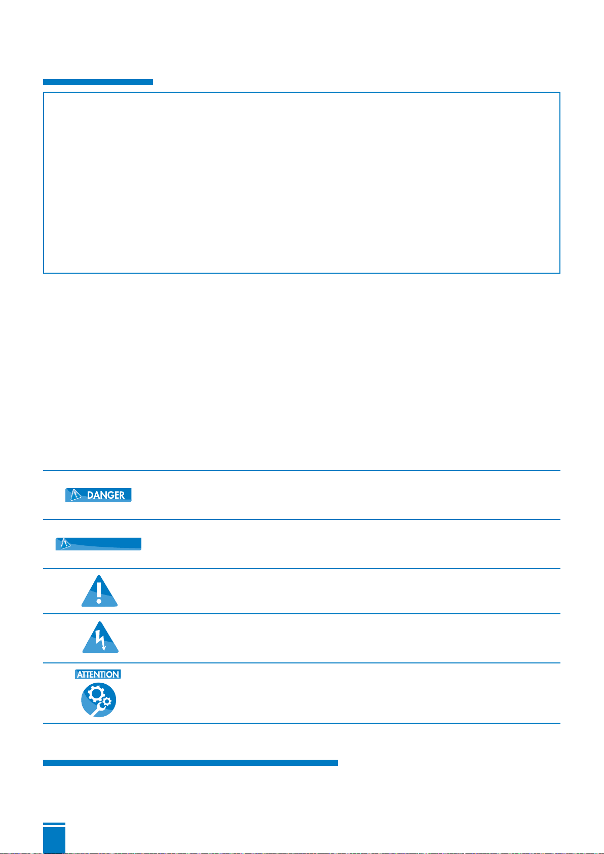
Danger
This term defines a high risk of danger, which can lead to death or serious
injury, if not avoided.
WARNING
Warning
This term defines a hazard which could cause a risk to the machine and its
operation, if it is not taken into account
Dangerous area
This symbol characterises hazards that could lead to death or injury.
Dangerous voltage
This symbol characterises dangers associated with the voltage and provides
information on voltage protection.
Property damage
This symbol, in combination with the keyword ATTENTION, characterises
dangers to the machine and its proper operation.
2. GENERAL INFORMATION
2.1 Areas of application
The twin pump control system ZPS 2.3 is principally used for the regulation of liquid levels. For this,

5
various sensors for level measurement can be used: floating switches, dynamic pressure, air bubble
level measurement systems, external 4- 20mA- sensors. The respective sensors to be employed can
be selected via the control program. Then two pumps are directly activated by motor contactors.
The pump changeover can be effected via time-control or level-control.
Furthermore, the following devices for error messages are available: acoustic signaler, 4 relay
alarm contacts potential-free (programmable for: high-water, combined fault, pump on, malfunction
pump, unit okay), safety circuits in the form of a turn-on- and a turn-off-delay, motor current
monitoring systems, motor temperature monitoring systems and flood control sensors guarantee a
safe operation of the pump station.
The control system is operated via 9 short travel key switches, the program settings are displayed
on an LCD display. All settings are saved so that they are available when the control system is
restarted. The display language can be changed.
Besides the actual operational parameters, the control system also saves the controlling process
and the occurring malfunctions in a record which can be displayed on the LCD display.
2.2 General characteristics
• Clear LCD display
• Hand- Stop- Auto- Function
• 1 acknowledgement button, 2 parameter
select buttons
• Menu which can be switched through
• Internal acoustic alarm
• Programmable operation and collective fault
signal potential-free
• Floating flood control potential-free
• Omnibus fault message potential-free
• Setting via short travel key switches
• Operating hours counter
• Maintenance interval counter
• Pump start counter
• Recording of fault protocol
• Electronic monitoring of the motor current
• Programmable turn-on-delay
• Programmable pump follow-up
• Programmable pump changeover interval
• Switchable service- and ATEX- mode
• Internal pressure sensor
• Level indication in cm
• 4 digital inputs for thermostatic switch
• 4 digital inputs for floating switch or reed
sensor
• 1 analogue input for transmitter 4-20mA
• 1 analogue pressure input 0-100(500) mBar
2.3 Technical data
Operating voltage 230V or 400V/AC/50-60 Hz
Voltage of control system 230V/AC/50-60 Hz
Power consumption env. 6VA
Pressure range 0-1mWs
Turn-on-delay 0-180 sec
Follow-up time 0-180 sec
Runtime monitoring 0-300 sec
Turn-on-delay 2 pumps 0-60 sec.
Motor current limitation 0.5- 14A
Fault protocol memory 32 memory positions
Maintenance interval counter 0 – 365 days, adjustable
Operating temperature range -20 - +60°C
Dimensions 180x180x90 mm
Max. pre-fuse 20A
Potential-free alarm contact 3 A max.
Degree of protection IP 65
Housing Polycarbonate

6
3. OPERATION OF THE CONTROL SYSTEM
The electronic pump control is equipped with a key lock. To unlock, please
press and hold (Selection) for 3 seconds. There will be an indication in
the display. Approximately 1 minute after the last actuation of any key the
keyboard will be locked again.
The automatic key lock after 1 minute can be deactivated in the menu, e.g. to
aid with maintenance works. The keylock is enabled with the service mode
switched-off only
3.1 Operator control panel and operational elements
3.1.1 Keys
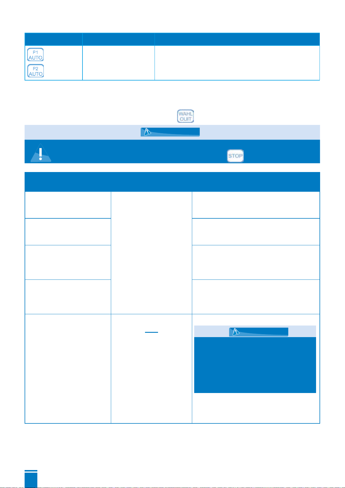
(MANUAL)
By pressing this key, the preferred pump is switched on without delay. Except for
the motor monitoring, no other function of the program is enabled.
The green LED ③of one pump flashes. ATTENTION : If the ATEX mode is enabled,
the pump can only be started if the turn-on level is exceeded !
The green LED is flashing. ATTENTION : The pump will be switched after 2
minutes. A restart of the pump is possible immediately.
Stops the pump motor without follow-up. The green LED goes out.
The pumps are actuated via the level evaluation of the selected sensor (see
point 3.1.4). All monitoring and safety functions are executed according to the
presetting.
③Signal-LED indicating when the pump is
operating :
- green: pump is on
- red: fault
② Short travel
key switches
① LCD display
(2 lines with 16
characters)

7
By pressing one of these two keys, the menu is switched to the next menu item in
the indicated direction.
If the menu is enabled, (see key SELECTION ), the set values can be modified
via those keys (some modifications are only possible in the operating mode
“Stop”). The more you press the key, the faster it scrolls.
(Selection/
Stop)
By pressing this key, the set values in the active menu are enabled. The activated
text will start to flash (modification mode) and can be modified by usin
g
.
By repeatedly pressing these keys, the set value becomes permanent (flashing
stops), which means that it will be saved even if the control system is turned off.
3.1.2 Indications on the display
Normal operation :
During operation of the control system, the upper line of the LCD display indicates the actual liquid
level or the switching status of the floating switch. In the lower line of the display, information about
the actual operational status of the control system of the pumps P1 and P2 will appear. If one pump
is running, the active motor current and the operating condition are displayed alternately. In case
of failure, the actual failure status is displayed (see point 3.1.6). The LEDs of the pump will flash
with a red light.
Parameter setting :
In the upper line, the designation of the parameter is displayed; the lower line displays the current
value of the parameter. The values can be modified by using the keys and as described
in 3.1.1.
Information retrieval :
Information values such as maintenance intervals, operating hours, pump starts and fault list can
be displayed and modified in the same way as the control parameters. Only the fault list saves 32
positions respectively. The recording is carried out by means of a shift register, which means that
the earliest error is deleted automatically.
3.1.3 Normal operation
During normal operation, the three operating modes are indicated on the display as follows.
Pressed key 2nd line on display Signification
Hand 1 P1 4,7A
Hand 2 P2 0,0A
The pump P1 and the pump P2 have been switched on
manually.
Stop 1 P1 0,0 A
Stop 2 P2 0,0 A
The pump motors are switched off. The level evaluation,
including the flood control, remains enabled.
The pump motor is not activated during
flooding alarm.
WARNING
8
Pressed key 2nd line on display Signification
Auto P1 4,7A
Auto P2 0,0A
The pumps are switched on or off, according to the level
requirement. Here, pump P1 is active at the moment.
3.1.4 Parameter setting
The following table shows the setting options and the effects of the individual parameters. A
parameter can be selected via the menu selection (see point 3.1.1).
For reasons of safety, the modification mode for the parameters can
only be enabled in the "Stop"- operation (key ).
1st line on display 2nd line on display
(set value) Signification
base load OFF Base load off ≤ Peak load
off
and
Base load on ≤ Peak load
on
Stop level base load.
Modifications only during Stop-
operation!
base load ON Start level base load.
Modifications only during Stop-
operation!
peak load OFF Stop level peak load, 2nd pump will switched
off.
Modifications only during Stop-
operation!
peak load ON Start level peak load, 2nd pump will
switched on.
Modifications only during Stop-
operation!
high water
(High water HW)
Peak load on < HW
and
HW ≤ final value of level
sensor
Flooding- alarm- level
Additionally, this level is constantly
evaluated on the input for the
floating switch HW, independent
from the selected level transmitter.
Thereby, if necessary, 2 different
HV-levels can be realised with 2
different transmitters.
Modification only possible in Stop-
mode !
WARNING
WARNING

9
1st line on display 2nd line on display
(set value) Signification
run-time
(Run-time change after)
is deactivated
until 300 sec.
At transgression of the adjusted time during
base load operation pumps do change.
‘IS DEACTIVATED’ effects that each
modification occurs only after reaching the
level ‘BASE LOAD OFF’.
This function may be used to monitor the
flow rate of the pump.
Here unto a time above the normal pump-
down time has to be adjusted. A switch
occurs if the requested pump has not
pumped down under the switch-on point
within the adjusted time. After 3 consecutive
the error "Run-time Alarm" occurs.
delay time 0 to 180 sec The turn-on delay of the pump only functions
after a restart of the control system (e.g.
after a power failure). With “normal” switch
operation via the levels N1 and N2, this
setting is not relevant.
This function may be used to avoid the
simultaneous switch-on of several pumping
stations after a mains failure.
overrun 0-180 sec. After having reached the turn-off level, the
pumps are still running for the adjusted
amount of time.
Interpump delay 0 to 60 sec. When both pumps are requested at the
same time, the second pump will be
switched on after the adjusted time, e.g. to
avoid mains overload.
pumps together - is activated
- is deactivated
If this function is deactivated, only one
pump works, e.g. to avoid overload of the
wastewater system.
max. current P1
max. current P2
0,0 to 14,0 A If the adjusted value is reached, the
monitoring system of the pump motor current
effectuates the shutdown of the pump,
accompanied by a notice of malfunction.
The malfunction has to be acknowledged
manually by pressing the key .
Attention : If the nominal current is
adjusted to 0 A no monitoring of the motor’s
charging rate occurs !
24 hours start is activated
is deactivated
Pump P1, P2 are briefly started if no request
occurs by the switch-on level within 24
hours.
If the ATEX mode is enabled, the 24h
starting is only taking place if the turn-off
level is exceeded.

10
1st line on display 2nd line on display
(set value) Signification
acoustic alarm is activated
is deactivated
The internal acoustic transmitter is switched
on or off. This setting has no influence on
the potential-free alarm signal.
interval alarm is activated
is deactivated
The alarm relay for the non-floating alarm
contact is synchronized or produces a
permanent signal.
pump changeover is activated
is deactivated
If the pump changeover is enabled a
changeover of the pumps occurs after each
pump down.
P1: therm.fault
P2: therm. fault
Thermostatic switch
P1 TH1 control loop
TH2 control loop
P2 TH3 control loop
TH4 control loop
is activated
is deactivated
The evaluation of the thermal contacts TH1
and TH3 (control loop) can be deactivated.
If this contact is open, the pump is shut
down and a fault is signalled. After the
contact TH1/TH3 (clipping circuit) has
cooled down and been closed again, the
pump restarts automatically.
After cooling down, the activation of the
pump in case of malfunction TH2/TH4 can
only be effected by acknowledging the
malfunction by pressing the key .
This contact can not be deactivated by
means of the software. If the pump is not
equipped with thermal contacts, a bridge
has to be inserted as a substitution for TH2/
TH4.
phase error is activated
is deactivated
The energization of all the 3 phases and the
proper phase sequence at the mains input
are monitored.
To be disabled for 230 V pumps.
ATEX - Mode is activated
is deactivated
If the ATEX mode is enabled, it is not
possible to switch on the pump if the turn-off
level is under-run. This also applies for the
HAND function and the 24h starting.
service mode is activated
is deactivated
If the service mode is disabled, it is
not possible to set the parameters. The
modification mode is only possible for the
service mode itself.
level controller
(=Level control)
intern. converter
float switch
4-20mA Interface
Level measurement via dynamic pressure
measurement
Level measurement via external sensor
Level measurement via floating switch
intern. converter matching
(=calibration) By pressing the key sequence
, the zero point of
the internal converter is adjusted. The
adjustment has to be carried out while
the pilot tube is emerged (with barometric
pressure). This adjustment is to be carried
out by a service technician only.
11
1st line on display 2nd line on display
(set value) Signification
20 mA => level 1 - 1250 cm Final value of the sensor at 20 mA
Signal contact 1-4 Possible signals :
- Fault high water
- Collective fault
- Pump 1 on
- Pump 2 on
- Fault pump 1
- Fault pump 2
- system OK
Kind of signal on contacts 1-4
The collective fault signal can be timed
Language Deutsch
English, etc...
Setting of the menu language
DD.MM.YYYY hh:mm see adjustments Date and time
Keylock on / off The keylock can be disabled. The key lock is
enabled with the service mode switched-off
only.
WLAN reset Disabled
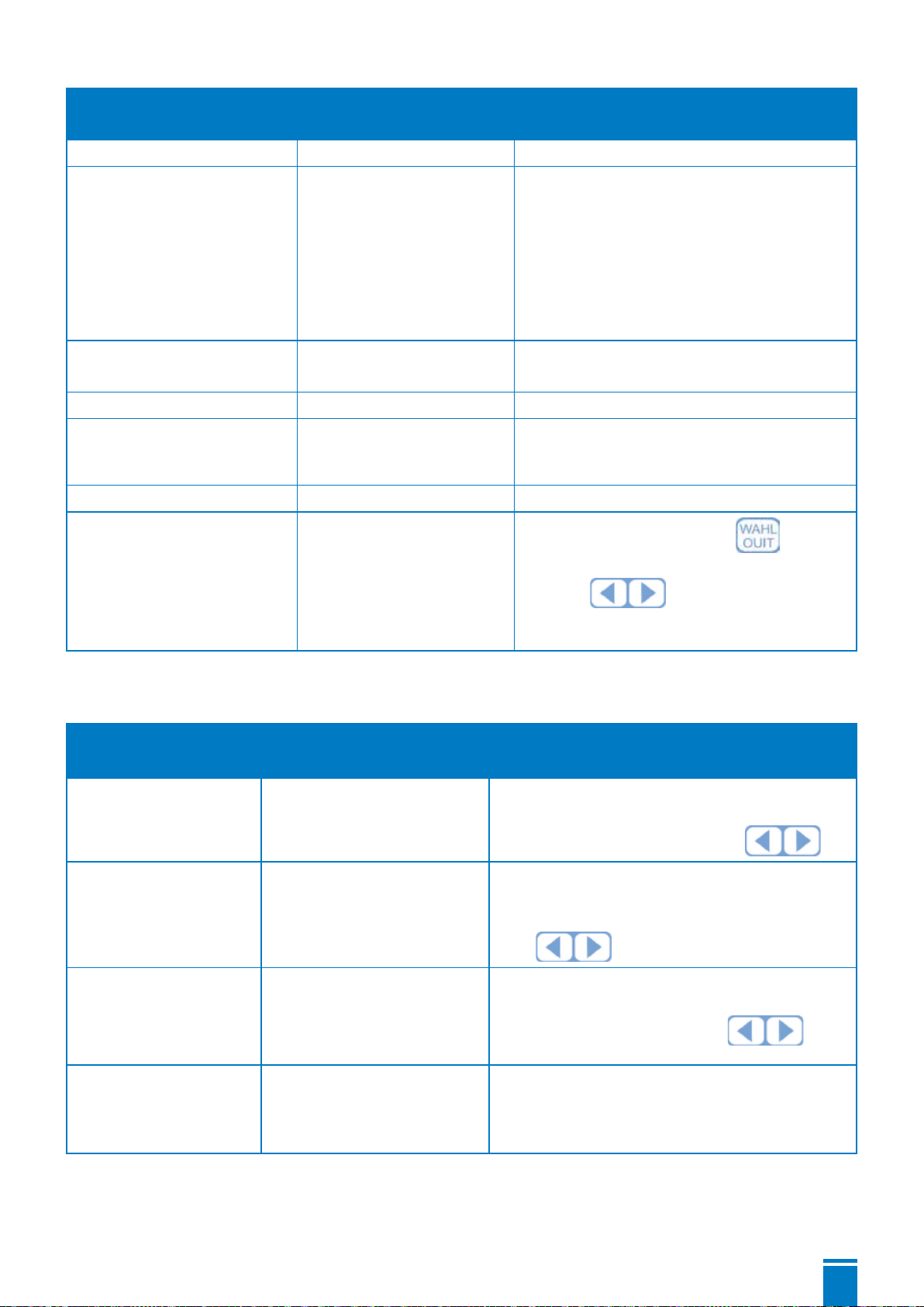
Fault protocol - - - After having pressed the key , the
protocol can be paged through by pressing
the keys .It is not possible to
change the data. The last 32 malfunctions
are saved in chronological order.
3.1.5 Information retrieval
The following table shows the signification of the operational data of the control system :
1st line on display 2nd line on display
(informational value) Signification
up time hours: X
(in hours)
Shows the cumulative operating times of the
control system in hours. The value can be
reset to 0 by pressing the keys .
total pump hours P1/P2 XXXX/XXXX
(in hours)
Shows the cumulative runtimes of the
pumps in hours. The value can be reset to 0
(separately for both pumps)by pressing the
keys .
pump starts P1/P2 XXXX/XXXX
(in number)
Shows the number of pump starts. The
value can be reset to 0 (separately for both
pumps) by pressing the keys .
next maintenance within days:XXXX
(in days)
Shows the number of days until the next
maintenance. The information is saved at
intervals of 4 hours. The initial value can be
preset between 365 and 0 days.
12
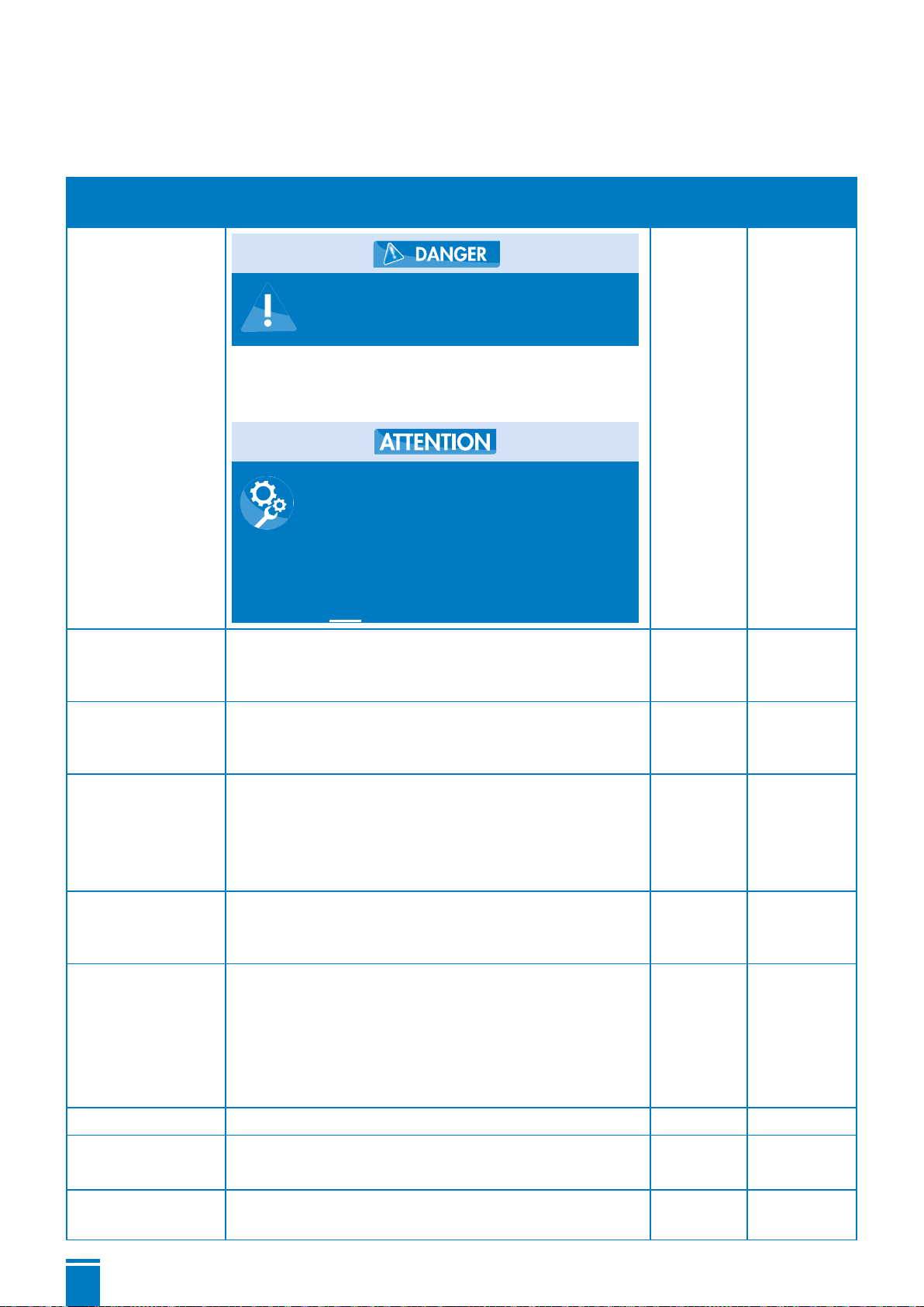
3.1.6 Warnings and notices of malfunction
The following warnings and notices of malfunction can be indicated on the display. In the fault
protocol, the data will be recorded :
2nd line on
display Signification Alarm Protocol
signal
Fault load
Current flow below 0,5 A. Either
no pump is connected, or a
phase is lacking.
This malfunction can be suppressed, if for the
motor current monitoring 0.0A are set in the menu
“current limitation“.
If both pump currents are set
to 0,0A, the control system is
running in the test mode. The
pumps are not deactivated. All
functions of the control system
are enabled. The motor current
is not monitored.
Yes Last
Fault pump 1
Fault pump 2
The motor current monitoring system has detected
an exceedance of the set limit value and has shut
down the pump motor.
Yes IP1
Fault high water The HW-sensor reports an alarm and switches on
the pump. The HW-malfunction acknowledges itself
when the turn-on level is reached again.
Yes HW
Fault
I<3mA
The external sensor is selected, but the current
is <3mA. There might be a disconnection, or
the sensor might be defective. The malfunction
acknowledges itself when the sensor current is
within the normal range.
Yes I<3mA
Fault
SW
The floating switches are connecting in the wrong
sequence (e.g. the lower floating switch is open
when the upper floating switch closes).
Yes SW
Pump 1
Fault TH1
Fault TH2
Pump 2
Fault TH3
Fault TH4
Activation of the thermal control of the pump
motor. The malfunction TH1 and TH3 acknowledge
themselves after the motor has cooled down; TH2
and TH4 have to be acknowledged manually.
Yes Pump 1
TH1
TH2
Pump 2
TH3
TH4
Phase fault A phase of the power supply has failed. Yes Dreh
Fault
ATEX
The ATEX mode is activated and the level is below
the switch-off point of the selected pump. Yes Atex
Run-time alarm The runtime monitoring of the pump has been
exceeded 3 times in succession. Yes Time
13
3.2 Assembly and electrical connections
All electrical connections are to be established by an authorised
professional only. Settings and adjustments on the control system
as well as the commissioning of the control system are to be
carried out by qualified persons only.
3.2.1 Mechanical fixation
The control system has to be fixed on an even surface. In order to fasten the control system, the
housing cover has to be opened.
3.2.2 Mains connection
The left cable gland is intended for the cable entry of the mains cable. The separate cables are
to be clamped into the spring terminals in the manner described below. According to the motor
which is used, a single-phase or a three-phase connection can be established.
The power supply has to be secured by an independent all-pole
fuse which can be switched off (max. 20 A).
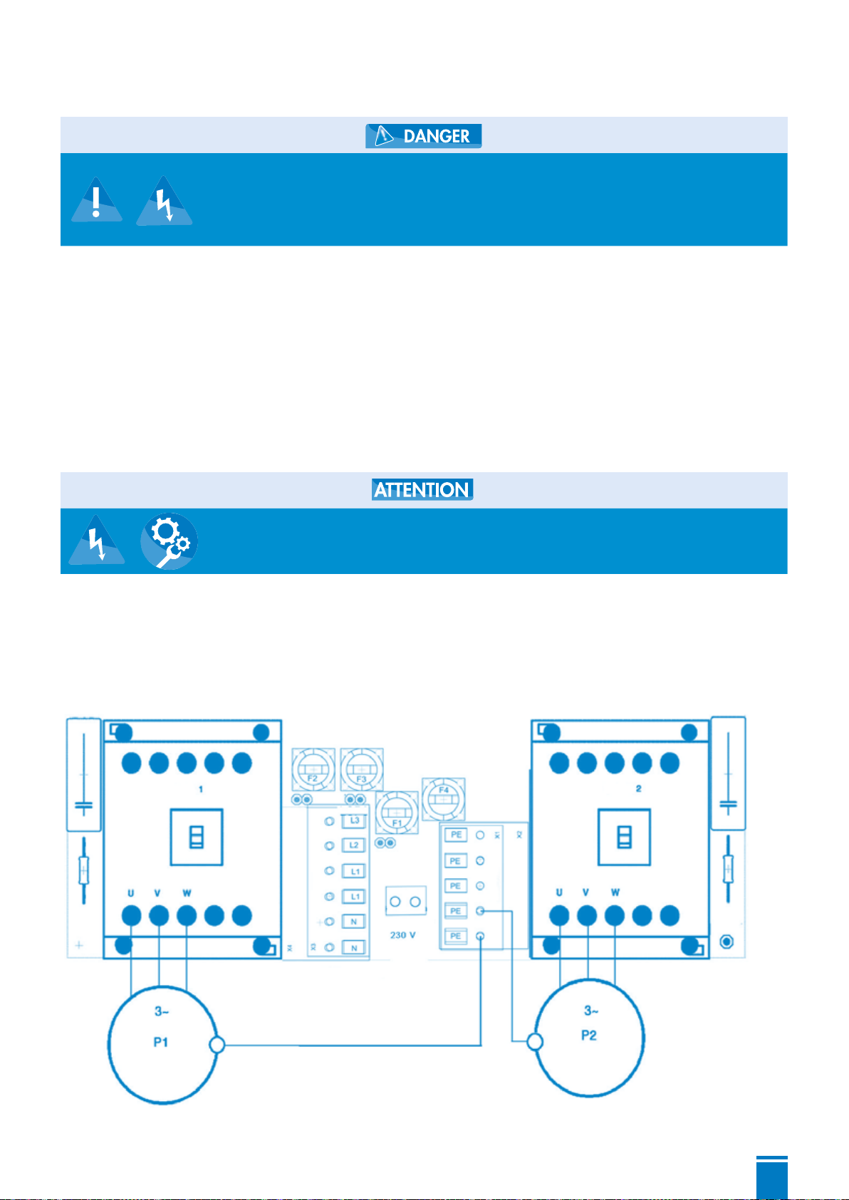
3.2.3 Connection of the pump motor
Either mono-phase or three-phase motors may be connected according to the below shown
connection diagram.
Connection of a 3-phase Motor :
Pump
Small-scale
consumer
Mains connection
230 V
Protective conductor
Pump
14
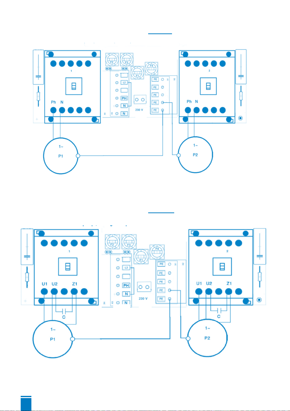
Connection of a single-phase Motor with internal capacitor :
Pump
Small-scale
consumer
Mains connection
Protective conductor
As for 230V pumps, a bridge is required between N - L2 in the mains connection
Pump
Connection of a single-phase Motor with external capacitor :
Pump
Small-scale
consumer
Mains connection
Protective conductor
As for 230V pumps, a bridge is required between N - L2 in the mains connection
Pump
For 230V pumps, a bridge between N-L2 is required in the mains connection.
For 230V pumps, a bridge between N-L2 is required in the mains connection.
15
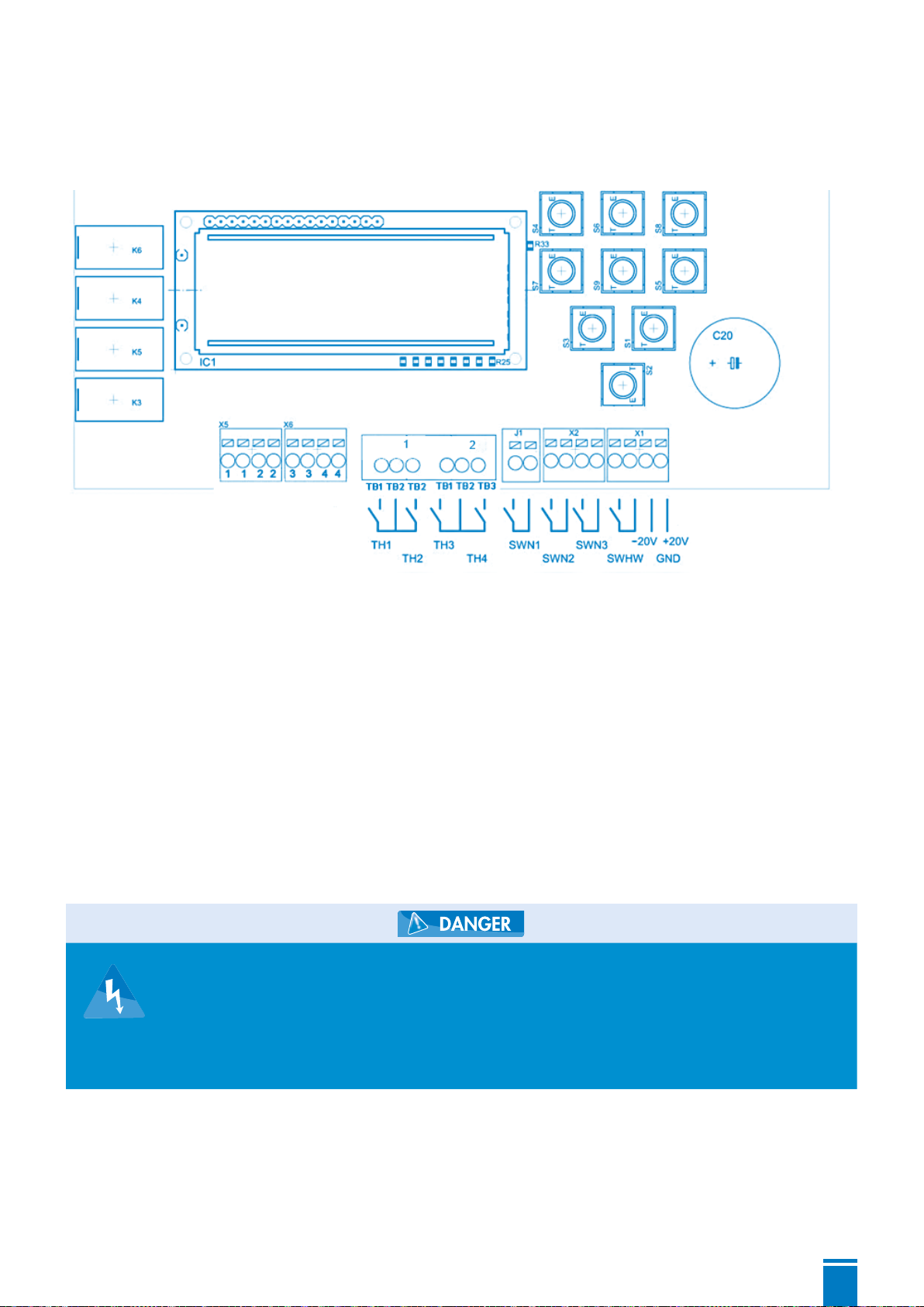
3.2.4 Connection of the external sensors
The external sensors are connected by means of the terminal strip on the upper circuit board.
The active sensor can be selected in the menu “level control” and “therm. malfunction”.
If the thermostatic switches TH2 and TH4 are not necessary, bridges have to be inserted on those
contact points. The thermostatic switches TH1 and TH3 can be deactivated via the menu therm.
malfunction.
The floating switches have to close when they are floating on the surface. The floating switches
have to be connected floatingly. The required signal voltage is generated in the control system and
amounts to 5V.
Assignment of the float switches:
SWN1 = pumps 1 and 2 off
SWN2 = pump on
SWN1 = peak load 2nd pump switched on
SWHW = high water alarm
For the usage in explosion-prone areas, either floating switches with the
corresponding permission, or intrinsically safe cut-off relays have to be
used.
The external sensor has to supply a measurement current between 4
and 20mA. The final value of 20 mA can be adjusted in the menu, so the
indication may occur in cm.
3.2.5 Utilisation of the internal sensor
An internal sensor, a pressure sensor 0 to 10 kPa is used (0 to 1mWs, 0 to 100 mbar). Other
measurement ranges can be realised on demand. On the lower side wall, a hose screw connection
6/8mm is located which is intended for the connection of the immersion pipe. The sensor used
is designed as a differential pressure converter, so that barometric variations are eliminated. The
De-energized
open
De-energized
closed
Pump Pump
Signal contacts
Floating
Use the 20 V output for
external 4-20 mA sensor only

16
menu item “internal converter – adjustment” serves for the accurate adjustment of the zero point.
In order to equalise possible air leaks inside the pneumatic level
measuring device, the pilot tube has to be fully emerged from the water
after completion of the pumping process. For this purpose, the adjustment
of a follow-up time of the according duration is necessary. Alternatively,
the small-size compressor set for the air bubbler level measurement
system can be used.
3.2.6 Signal contacts
The 4 potential-free signal contacts are located in the upper circuit board (left).
The 4 signal contacts are free programmable: the contacts 1 and 2 are opened in case of power
failure and the contacts 3 and 4 are closed in case of power failure.
If the power supply of the control is okay, then the signal contacts are closed in case of a fault or
signal.
3.3 Commissioning of the control system
After the complete connection of the pump cables, the mains power supply and the level sensor,
the parameters can be set after the mains voltage has been applied. Only trained personnel are
allowed to set those parameters.
Now the plant can be commissioned by pressing the key . During the conduction of several
test runs, the set switch points have to be checked, and, if necessary, corrected.
Checking of the control system without pumps :
In order to be able to check the control system without a pump, the following standard settings are
required :
1. Connect the control system to a single-phase network (connection of N and L1)
2. Set motor current limitations for both pumps to 0.0 A
3. Switch off rotary field
4. Bridge thermal contacts TH2 AND TH4
5. Disable thermic error for pump 1 and pump 2.
If the respective level sensors are connected, all program functions can be checked without having
to connect the pumps.
4. DISPOSAL
Only for EU-countries
Do not dispose of the control system with the regular household garbage!
According to the European directive 2012/19/EG about waste electric and
electronic equipment and the transposition into national law, used electric tools.
have to be collected separately and recycled in an environmentally compliant
manner.

ZUSAMMENFASSUNG
Copyright / Impressum - Installations-, Wartungs- und Montageanleitung Control Box ZPS 2.3 - Originalbetriebsanleitung - Alle
Rechte vorbehalten
Die Inhalte dieses Dokuments dürfen nicht ohne schriftliche Genehmigung des Herstellers verbreitet, reproduziert, geändert oder
an Dritte weitergegeben werden. Dieses Dokument kann ohne vorherige Ankündigung geändert werden.
Stand der Betriebsanleitung: November 2019
1. SICHERHEIT ...................................................p 18
2. ALLGEMEINE ANGABEN .............................p 18
2.1 Anwendungsgebiete.............................................p 18
2.2 Merkmale ...........................................................p 19
2.3 Technische Daten .................................................p 19
3. BEDIENUNG DER STEUERUNG...................p 20
3.1 Bedientableau und Bedienelemente........................p 20
3.1.1 Tasten...........................................................p 20
3.1.2 Display- Anzeigen..........................................p 21
3.1.3 Normalbetrieb...............................................p 21
3.1.4 Parametereinstellung.......................................p 22
3.1.5 Informationsabruf...........................................p 25
3.1.6 Warnungen und Störmeldungen.......................p 26
3.2 Montage und elektrische Anschlüsse.......................p 27
3.2.1 Mechanische Befestigung................................p 27
3.2.2 Netzanschluss................................................p 27
3.2.3 Anschluss des Pumpenmotors...........................p 27
3.2.4 Anschluss der externen Sensoren......................p 29
3.2.5 Verwendung des internen Sensors ....................p 30
3.2.6 Meldekontakte...............................................p 30
3.3 Inbetriebnahme der Steuerung ...............................p 30
4. ENTSORGUNG...............................................p 31

18
1. SICHERHEIT
ACHTUNG
Dieses gerät darf nicht von kindern, personen mit eingeschränkten
physischen, sensorischen und geistigen fähigkeiten, sowie personen
ohne technische einweisung verwenset werden. Die bedienung
sowie der sichere gebrauch sind nur nach ordnungsgemäßer
einweisung oder unter aufsicht von eingewiesenen personen
statthaft.
STROMANSCHLUSS :
Die elektrische Montage muss von einem Elektrotechniker realisiert werden.
Die Versorgungsleitung des Geräts muss geerdet (Klasse I) und durch einen
hochempfindlichen Schutzschalter (30 mA) geschützt sein. Geräte ohne Steckdose
müssen an einen Hauptschalter an das Stromnetz angeschlossen werden, der
die Trennung aller Pole gewährleistet (mindestens 3 mm Kontaktabstand). Der
Anschluss darf ausschließlich der Stromzufuhr des Geräts dienen.
Wenn das Stromkabel beschädigt ist, muss es vom Hersteller, seinem Kundendienst
oder ähnlich qualifiziertem Fachpersonal ersetzt werden, um Gefahren zu vermei-
den.
Kennzeichnung von Hinweisen in der Betriebsanleitung
Gefahr
Dieser Begriff definiert eine Gefahr mit erhöhtem Risiko, das zum Tod oder
schweren Verletzungen führen kann, wenn sie nicht vermieden wird.
Warnung
Dieser Begriff definiert eine Gefahr, die zu einem Risiko für die Maschine und
ihren Betrieb führen kann, wenn sie nicht vermieden wird.
Gefahrenbereich
Dieses Symbol warnt in Kombination mit einem Schlüsselwort vor Gefahren,
die zum Tod oder zu Verletzungen führen können.
Gefährliche elektrische Spannung
Dieses Symbol warnt in Kombination mit einem Schlüsselwort vor Gefahren
der elektrischen Spannung und informiert über den Schutz vor elektrischer
Spannung.
Sachschäden
Dieses Symbol warnt in Kombination mit dem Schlüsselwort ACHTUNG vor
Gefahren für die Maschine.
2. ALLGEMEINE ANGABEN
2.1 Anwendungsgebiete
Die Doppelpumpensteuerung ZPS 2.3 wird vorwiegend zur Regulierung von Flüssigkeitsniveaus
19
eingesetzt. Dabei können verschiedene Fühler zur Niveauerfassung eingesetzt werden:
Schwimmschalter, Staudruck, Lufteinperlung, externe 4- 20mA- Sensoren. Die jeweils zum Einsatz
kommenden Fühler können im Steuerprogramm ausgewählt werden. Motorschütze steuern dann
direkt zwei Pumpen an. Der Pumpenwechsel kann dabei zeit- oder niveaugesteuert erfolgen. Zwei
einstellbare Schaltniveaus gestatten den gleichzeitigen Betrieb beider Pumpen.
Weiterhin stehen folgende Einrichtungen zur Störungsmeldung zur Verfügung:
akustischer Signalgeber, 4 Relaismeldekontakte potentialfrei frei programmierbar (für Hochwasser,
Sammelstörung, Pumpe ein, Störung Pumpe, Anlage in Ordnung), Sicherheitsschaltungen in Form
vonEinschalt-undAusschaltverzögerung,Motorstromüberwachung,Motortemperaturüberwachung
und Hochwassersensoren gewährleisten einen sicheren Betrieb der Pumpenanlage.
Die Bedienung der Steuerung erfolgt über 9 Kurzhubtasten, die Programmeinstellungen werden
über ein LCD- Display angezeigt. Sämtliche Einstellungen werden gespeichert und stehen beim
Neustart der Steuerung wieder zur Verfügung. Die Landessprache im Display ist umschaltbar.
Die Steuerung speichert neben den eigentlichen Betriebsparametern auch den zeitlichen
Steuerungsverlauf und die auftretenden Fehler in einem Protokoll, das im LCD-Display angezeigt
werden kann.
2.2 Merkmale
• LCD- Klartext- Anzeige
• Hand- Stopp- Auto- Funktion je Pumpe
• 1 Quittierungstaster,
2 Parameterauswahltaster
• Durchschaltbares Menü
• Interner akustischer Alarm
• Programmierbare Betriebs-und
Störmeldungen potentialfrei
• Einstellung über Kurzhubtaster
• Betriebsstundenzähler
• Wartungsintervallzähler
• Pumpenstartzähler
• Fehlerprotokollaufzeichnung
• Elektronische Überwachung des
Motorstromes
• Programmierbare Einschaltverzögerung
• Programmierbarer Pumpennachlauf
• Programmierbares Pumpenwechsel- Intervall
• Schaltbarer Service- und ATEX- Mode
• Interner Drucksensor
• Füllstandsangaben in cm
• 4 digitale Eingänge für Thermoschalter
• 4 digitale Eingänge für Schwimmschalter
oder Reedfühler
• 1 Analogeingang für Geber 4-20mA
• 1 analoger Druckeingang 0- 100(500) mBar
2.3 Technische Daten
Betriebsspannung 230V oder 400V/AC/50- 60 Hz
Steuerspannung 230V/AC/50-60 Hz
Leistungsaufnahme env. 6VA
Druckbereich 0-1mWs
Einschaltverzögerung 0-180 sec
Nachlaufzeit 0-180 sec
Pumpenwechselintervall 0-300 sec
Einschaltverz. 2 Pumpe 0-60 sec.
Motorstrombegrenzung 0,5- 14A
Störprotokollspeicher 32 Speicherpositionen
Wartungsintervallzähler 0 – 365 Tage, einstellbar
Temperatureinsatzbereich -20 - +60°C
Abmessungen 180x180x90 mm
max. Vorsicherung. 20A
Alarmkontakt potentialfrei 3 A max.
Schutzgrad IP 65
Gehäuse Polycarbonat
Table of contents
Languages:
Other SFA Control Unit manuals


Popular Control Unit manuals by other brands

AWID
AWID SENTINEL-SENSE ADB-510 Installation & operation manual

Emerson
Emerson Fisher 167DA instruction manual

Burkert
Burkert 2301 Series operating instructions

phytron
phytron phyMOTION PIDM01.1 TRANSLATION OF THE ORIGINAL GERMAN MANUAL

Wistron NeWeb
Wistron NeWeb DHUK-SY22 user manual

Brand Hydraulics
Brand Hydraulics FG52 Installation & user guide

Aerotech
Aerotech UFM-ST Hardware manual

Bosch
Bosch Professional GCY 42 Original instructions

Hewalex
Hewalex CKF 3325 installation manual

Federal Signal Corporation
Federal Signal Corporation Serial Interface Module Installation and programming instructions

Bosch
Bosch IO-BOX32 manual

SG Wireless
SG Wireless SGW101 Series manual


