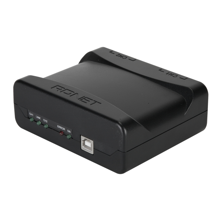
RCF RDNET CONTROL 8 User manual

OWNER MANUAL
MANUALE D’USO
RDNET CONTROL 8 -‘RDNET’ CONTROL UNIT
-UNITA’ DI CONTROLLO
DELLA RETE “RDNET”


INDEX
INDICE
ENGLISH
SAFETY PRECAUTIONS
INSTALLATION
DESCRIPTION
FRONT PANEL
REAR PANEL
SUBNET CONNECTION
NOTES ABOUT THE RDNET SOFTWARE
RDNET SOFTWARE INSTALLATION
LOUDSPEAKER BYPASS SWITCH
RDNET SOFTWARE (release 1.0.0.68)
ASSIGN AN OBJECT TO A GROUP
ASSIGN AN OBJECT TO AN ALGORITHM
ASSIGNING MULTIPLE OBJECTS TO AN ALGORITHM
EXAMPLE OF ANOTHER OBJECT
RDNET SOFTWARE REPAIR AND REMOVE
SPECIFICATIONS
ITALIANO
AVVERTENZE PER LA SICUREZZA
INSTALLAZIONE
DESCRIZIONE
PANNELLO FRONTALE
PANNELLO POSTERIORE
COLLEGAMENTO DELLE SOTTORETI
NOTE SUL SOFTWARE RDNET
INSTALLAZIONE DEL SOFTWARE RDNET
FUNZIONAMENTO DEL TASTO BYPASS DEI DIFFUSORI
UTILIZZO DEL SOFTWARE RDNET (rif. ver. 1.0.0.68)
ASSEGNAZIONE DI UN MODULO AD UN GRUPPO
ASSEGNAZIONE DI UN MODULO AD UN ALGORITMO
ASSEGNAZIONE MULTIPLA DI MODULI AD UN ALGORITMO
ESEMPIO DI UN ALTRO MODULO
RIPARAZIONE E DISINSTALLAZIONE DEL SOFTWARE RDNET
DATI TECNICI
4
6
6
7
8
9
10
10
14
15
25
26
27
28
28
29
32
34
34
35
36
37
38
38
42
43
53
54
55
56
56
57

4
ENGLISH
IMPORTANT
Before connecting and using this product, please read this instruction manual carefully and
keep it on hand for future reference.
The manual is to be considered an integral part of this product and must accompany
it when it changes ownership as a reference for correct installation and use as well as
for the safety precautions. RCF S.p.A. will not assume any responsibility for the incorrect
installation and / or use of this product.
WARNING: To prevent the risk of fire or electric shock, never expose this product to rain
or humidity.
SAFETY PRECAUTIONS
1. All the precautions, in particular the safety ones, must be read with special
attention, as they provide important information.
2.1 POWER SUPPLY FROM MAINS
a. The mains voltage is sufficiently high to involve a risk of electrocution; therefore, never
install or connect this product when its power cable is plugged in.
b. Before powering up, make sure that all the connections have been made correctly and
the voltage of your mains corresponds to the voltage shown on the rating
plate on the unit, if not, please contact your RCF dealer.
c. The metallic parts of the unit are earthed by means of the power cable.
An apparatus with CLASS I construction shall be connected to a mains socket outlet
with a protective earthing connection.
d. Protect the power cable from damage.
Make sure it is positioned in a way that it cannot be stepped on or crushed by objects.
e. To prevent the risk of electric shock, never open the product: there are no parts
inside that the user needs to access.
3. Make sure that no objects or liquids can get into this product, as this may cause a short
circuit. This apparatus shall not be exposed to dripping or splashing. No objects filled with
liquid, such as vases, shall be placed on this apparatus. No naked sources (such as lighted
candles) should be placed on this apparatus.
4. Never attempt to carry out any operations, modifications or repairs that are not expressly
described in this manual.
Contact your authorized service centre or qualified personnel should any of the following
occur:
-The product does not function (or functions in an anomalous way).
-The power supply cable has been damaged.
-Objects or liquids have got in the unit.
-The product has been subject to a heavy impact.
5. If this product is not used for a long period, disconnect the power cable.
6. If this product begins emitting any strange odours or smoke, switch it off immediately
and disconnect the power supply cable.
7. Do not connect this product to any equipment or accessories not foreseen.
For suspended installation, only use the dedicated anchoring points and do not try to
hang this product by using elements that are unsuitable or not specific for this purpose.
Alsocheckthesuitabilityofthesupportsurfacetowhichtheproductisanchored(wall,ceiling,
structure,etc.),andthecomponentsusedfor attachment (screwanchors,screws,brackets not
suppliedby RCFetc.),whichmust guaranteethe securityof thesystem /installation overtime,
also considering, for example, the mechanical vibrations normally generated by transducers.
To prevent the risk of falling equipment, do not stack multiple units of this product unless
this possibility is specified in the user manual.
IMPORTANT
WARNING
SAFETY
PRECAUTIONS

5
ENGLISH
7. Do not connect this product to any equipment or accessories not foreseen.
For suspended installation, only use the dedicated anchoring points and do not try to hang
this product by using elements that are unsuitable or not specific for this purpose.
Also check the suitability of the support surface to which the product is anchored (wall,
ceiling, structure, etc.), and the components used for attachment (screw anchors, screws,
brackets not supplied by RCF etc.), which must guarantee the security of the system /
installation over time, also considering, for example, the mechanical vibrations normally
generated by transducers.
To prevent the risk of falling equipment, do not stack multiple units of this product unless
this possibility is specified in the user manual.
8. RCF S.p.A. strongly recommends this product is only installed by professional
qualified installers (or specialised firms) who can ensure correct installation
and certify it according to the regulations in force.
The entire audio system must comply with the current standards and
regulations regarding electrical systems.
9. Supports and trolleys
The equipment should be only used on trolleys or supports, where necessary, that are
recommended by the manufacturer. The equipment / support / trolley assembly must be
moved with extreme caution. Sudden stops, excessive pushing force and uneven floors may
cause the assembly to overturn.
10. Mechanical and electrical factors need to be considered when installing a professional
audio system (in addition to those which are strictly acoustic, such as sound pressure,
angles of coverage, frequency response, etc.).
11. Hearing loss
Exposure to high sound levels can cause permanent hearing loss. The acoustic pressure
level that leads to hearing loss is different from person to person and depends on the
duration of exposure. To prevent potentially dangerous exposure to high levels of acoustic
pressure, anyone who is exposed to these levels should use adequate protection devices.
When a transducer capable of producing high sound levels is being used, it is therefore
necessary to wear ear plugs or protective earphones.
See the technical specifications in loudspeaker instruction manuals to know their maximum
sound pressure levels.
12. To prevent the occurrence of noise, use screened cables only and avoid putting them
close to:
-Equipment that produces high-intensity electromagnetic fields
(for example, high power transformers)
-Mains cables
-Loudspeaker lines.
13. Situate this product far from any heat sources.
14. Never force the control elements (keys, knobs, etc. ).
15. Do not use solvents, alcohol, benzene or other volatile substances for cleaning the
external parts of this product. Use a dry cloth.

6
ENGLISH
RCF S.P.A. THANKS YOU FOR PURCHASING THIS PRODUCT, WHICH HAS BEEN
DESIGNED TO GUARANTEE RELIABILITY AND HIGH PERFORMANCES.
DESCRIPTION
This device can be installed into a 19” rack cabinet (1 unit) with 4 screws, thanks to its
rack ears.
RDNET is a proprietary protocol of a network that allows to connect up to 256
compatible audio devices (i.e. professional RCF loudspeakers mod.TTL55-A, TTL33-A,
TTL31-A, etc.) to a computer (PC with Microsoft Windows® o. s.) to check and remote
control them.
RDNET CONTROL 8 unit routes all data between the PC and audio devices.
The RDNET system allows to monitor every device, checking voltages and currents,
temperatures, audio signal RMS values, cooling fans, etc. .
The PC cyclically requires the RDNET CONTROL 8 unit the operating state of audio
devices that make up the communication network. All data are collected by the central
unit that performs a sequential scan of all audio devices.
Digital address allocation is automatic.
Information relating to the functioning of all audio devices is acquired in real-time,
feature that allows a network global view.
It is possible to check each single audio device and edit its parameters (e.g. output level,
mute, equalization, delay, etc.) by using the PC software.
The audio device overall configuration can be saved as file in the PC and later reloaded.
It is possible to synchronize all parameter values of the RDNET CONTROL 8 unit to the
ones of the PC software preset.
The link between the PC and the RDNET CONTROL 8 unit can be made through either
the USB port or ETHERNET, the latter is useful when the PC is far or it is necessary to link
the RDNET CONTROL 8 unit to an ETHERNET net already wired.
USB link shall be at least version 1.1 (2.0 is OK) and
can be used when the PC is close to the central unit (a
few metres).
The RDNET CONTROL 8 unit can manage up to 8
subnets. Up to 32 audio devices can be connected
to each subnet (8 subnets x 32 = total 256 audio
devices).
INSTALLATION
PC
USB / ETHERNET
RDNET CONTROL 8
EIA RS-485
AUDIO
DEVICES
(max. 32
per subnet)
SUBNET 1
SUBNET 2
SUBNET 3
SUBNET 4
SUBNET 5
SUBNET 6
SUBNET 7
SUBNET 8

7
ENGLISH
SUBNET PAIRS LINKED IN RINGS
As future option, it will be possible to link subnet
pairs in rings (to verify line integrity).
When using 4 subnet pairs, the max. total quantity of
audio devices that can be connected is 128.
1CH 1 LED indicating (when flashing) data transmission / reception in the subnet 1.
2 CH 2 LED indicating (when flashing) data transmission / reception in the subnet 2.
3CH 3 LED indicating (when flashing) data transmission / reception in the subnet 3.
4 CH 4 LED indicating (when flashing) data transmission / reception in the subnet 4.
5CH 5 LED indicating (when flashing) data transmission / reception in the subnet 5.
6CH 6 LED indicating (when flashing) data transmission / reception in the subnet 6.
7 CH 7 LED indicating (when flashing) data transmission / reception in the subnet 7.
8 CH 8 LED indicating (when flashing) data transmission / reception in the subnet 8.
9LINK 1LED indicating (when lit) that subnets 1 and 2 are linked in a ring.
PLINK 2 LED indicating (when lit) that subnets 3 and 4 are linked in a ring.
{LINK 3 LED indicating (when lit) that subnets 5 and 6 are linked in a ring.
}LINK 4 LED indicating (when lit) that subnets 7 and 8 are linked in a ring.
qERROR LED indicating (when lit) an error during data transmission / reception.
wCARD READER slot for an SD (‘Secure Digital’) flash memory.
This slot is not enabled in the current firmware release.
eUSB port (type B) for the computer (local) link.
rPOWER LED indicating (when lit) that the unit is switched on.
tPOWER switch (I:ON, O:OFF).
FRONT PANEL
9 10 11 12 13 14 15 1716
1 3 5 72 4 6 8
PC
USB / ETHERNET
RDNET CONTROL 8
EIA RS-485
2
3
4
5
6
7
8
ex.: 4 SUBNET PAIRS LINKED IN RINGS
AUDIO
DEVICES
(max. 32
per subnet)
SUBNET 1

8
ENGLISH
y‘Powercon’ connector for the power cable.
Operating voltage: 100 ÷ 240 V ac (50 – 60 Hz).
uETH ETHERNET port (to link a remote computer).
RJ45 CONNECTOR (CAT5 cable):
pin
1- TX+
2- VDD
3- TX–
4- RX+
5- digital ground
6- RX–
7- not used
8- ground
iCH1 Subnet 1 RDNET port, through either an RJ 45 connector (CAT5 cable ) or a
3-pole XLR socket.
DoNoT coNNecT boTh RJ 45 aND XLR coNNecToRs aT The same RDNeT poRT!
RJ 45 CONNECTOR
pin
1 – available for other functions (for example: audio signal +, hot)
2 – available for other functions (for example: audio signal –, cold)
3 – available for other functions (for example: analogue ground)
4 – digital ground
5 – digital ground
6 – available for other functions (for example: power supply)
7 – RS 485 A
8 – RS 485 B
XLR SOCKET
pin
1 – digital ground
2 – RS 485 A
3 – RS 485 B
REAR PANEL
18 19 20 2422 2621 2523 27
XLR SOCKET 3
12
RJ 45 SOCKET
|1|2|3|4|5|6|7|8|
RJ 45 PLUG
8 46 2
7 35 1

9
ENGLISH
oCH2 Subnet 2 RDNET port, through either an RJ 45 connector (CAT5 cable)
or a 3-pole XLR socket (see i).
pCH3 Subnet 3 RDNET port, through either an RJ 45 connector (CAT5 cable)
or a 3-pole XLR socket (see i).
[CH4 Subnet 4 RDNET port, through either an RJ 45 connector (CAT5 cable)
or a 3-pole XLR socket (see i).
]CH5 Subnet 5 RDNET port, through either an RJ 45 connector (CAT5 cable)
or a 3-pole XLR socket (see i).
ACH6 Subnet 6 RDNET port, through either an RJ 45 connector (CAT5 cable)
or a 3-pole XLR socket (see i).
SCH7 Subnet 7 RDNET port, through either an RJ 45 connector (CAT5 cable)
or a 3-pole XLR socket (see i).
DCH8 Subnet 8 RDNET port, through either an RJ 45 connector (CAT5 cable)
or a 3-pole XLR socket (see i).
Each of the 8 available RDNET ports of the RDNET CONTROL 8 unit can be connected
to max. 32 compatible audio devices (linked in ‘daisy-chain’).
Example: the RDNET CONTROL 8 port 1 is connected to the DATA IN input of a RCF
TTL-55A loudspeaker, of which DATA LINK parallel output is linked to the input of the
following TTL55-A loudspeaker.
INThe eXampLe above, [n] Is aNumbeR fRom 3 To 32 (maX. quaNTITy of auDIo DevIces ThaT caN be
coNNecTeD To asubNeT).
The total CAT 5 cable length of a subnet cannot exceed 900 metres (c. 2950 feet).
As future option, it will be possible to link subnet pairs in rings (to verify line integrity).
For instance: the RDNET CONTROL 8 port 1 is connected to the DATA IN input of a
RCF TTL55A loudspeaker, of which DATA LINK parallel output is linked the input of the
following TTL55A loudspeaker. The DATA LINK output of the last TTL55A loudspeaker of
the line is connected the RDNET CONTROL 8 port 2.
SUBNET CONNECTION
RDNET
CONTROL 8 TTL55-A [1] TTL55-A [2] TTL55-A [n]
DATA IN DATA IN DATA INDATA LINK DATA LINK DATA LINK
CH 1
ACTIVE
LINK
ACTIVE
LINK
ACTIVE
LINK

10
ENGLISH
LINK 1 9, LINK 2 P, LINK 3 {eLINK 4 }fRoNT paNeL LeDsINDIcaTe The RINg
coNNecTIoN of The RespecTIve paIR of subNeTs.
The RDNET software is protected by international copyright laws and is to be used to
configure the RCF RDNET system only.
It is not allowed to modify or change or try to decompile this software.
In no event shall RCF S.p.A. be liable to end-users for any damage whatsoever, including
but not limited to financial damages for loss of business profits or business information
due to the software use or inability to use this product.
The foregoing provision is effective even if RCF S.p.A. has been advised of the possibility
of such damages.
Even if the SOFTWARE has any material, verifiable and reproducible program errors, RCF
S.p.A. shall have no obligation to modify such errors.
Minimum requirement: a PC with Microsoft ‘Windows® XP’, ‘Vista’ or ‘7’ operating
system, having an available USB port and / or ETHERNET.
Before installing a new software release, it is necessary to remove the previous version (if
installed) by running Start > Programs > RCF Group > RDNet > Uninstall and (in
case) disconnect the USB cable between the computer and the RDNET CONTROL 8 unit.
Run setup.exe (inside the ‘setup’ folder) to start the software installation.
If the installed PC software does not include the release 4.0 of MS “.NET Framework”
(necessary to install the RDNET software), it will be show the request for downloading
from the web (for free).
NOTES ABOUT THE RDNET SOFTWARE
RDNET
CONTROL 8 TTL55-A [1] TTL55-A [2] TTL55-A [n]
DATA IN DATA IN DATA INDATA LINK DATA LINK DATA LINK
CH 1
CH 2
ACTIVE
LINK
ACTIVE
LINK
ACTIVE
LINK
RDNET SOFTWARE INSTALLATION

11
ENGLISH
If internet is available, click the YES button
to open the web page where it is possible
to download the last release of the ‘.NET
Framework’ software, then install it.
Read the license agreement.
Click ‘I Agree’ to accept and proceed with the
software installation.
Click the NEXT > button to proceed.
If ‘.NET Framework 4.0’ has been previously
installed, the RDNET software wizard starts.
Click the NEXT > button to proceed.

12
ENGLISH
It is now possible to change the installation folder
(directory) of the RDNET software (or keep the
default path).
Choose if the software can be used by ‘Everyone’
or ‘Just me’.
Click the NEXT > button to proceed.
The wizard reminds you that it is necessary to
disconnect the USB cable between the computer
and the RDNET CONTROL 8 unit in order to install
USB drivers properly.
Check if the USB cable is actually disconnected
before proceeding.
Then, it is required the installation confirmation.
If you are sure, click the NEXT > button to
proceed and start the installation.
Await the installation is complete.

13
ENGLISH
While waiting, the installation progress bar is
shown.
As soon as the installation ends (no error), the
‘Installation Complete’ window will appear.
Click the CLOSE button to exit.
Connect the USB cable or ETHERNET between the
computer and the RDNET CONTROL 8 unit before
running the software.

14
ENGLISH
Loudspeaker not linked to RDNET
(device not listed, the ‘LINK’ LED is off)
The BYPASS switch is pressed ?
NO YES
The keyboard configuration is applied The loudspeaker loads its stored preset
The ‘BYPASS’ LED is off The ‘BYPASS’ LED is lit
Loudspeaker linked to RDNET
(device listed, the ‘LINK’ LED is lit)
All data concerning the selected preset and the operating mode are sent to the computer.
ITIs possIbLe To eDIT aLL paRameTeRs aND sToRe Them IN LouDspeakeRs by usINg The pc sofTwaRe.
IfThe RDNeT NeT Is DIscoNNecTeD, ThIs pRoceDuRe wILL ResTaRT fRom The begINNINg.
fILTeR DaTa caNNoT be seNT To LouDspeakeRs fRom pc. The oNLy way To kNow If LouDspeakeR DaTa
aRe IDeNTIcaL To The pc sofTwaRe seTTINgs Is To check ThaT The LouDspeakeR (oR aNy oTheR DevIce) Is
syNchRoNIzeD.
IfThe sofTwaRe Is ‘oNLINe’, LouDspeakeR maIN seTTINgs aRe RemoTe coNTRoLLeD ThRough RDNeT
NeTwoRk. IfThe sofTwaRe Is ‘offLINe’, LouDspeakeR maIN seTTINgs DepeND oN ITs INpuT paNeL bypass
swITch (ThaT RecaLLs The LasT saveD coNfIguRaTIoN). see The foLLowINg TabLe.
In every RDNET compatible loudspeaker, when pressing the BYPASS switch, it is possible
to recall a previously stored preset and disable the loudspeaker keyboard.
The following flowchart indicates the BYPASS function:
LOUDSPEAKER BYPASS SWITCH
RDNET software
(network status)
offline
offline
online
online
Loudspeaker
BYPASS switch
OFF
ON
OFF
ON
Loudspeaker
BYPASS LED
OFF
ON
OFF
ON
Loudspeaker
configuration
According to the loudspeaker front panel
Last saved configuration
Settings through RDNET network

15
ENGLISH
assooN as The RDNeT coNTRoL 8 uNIT Is TuRNeD oN, aLL DevIces wILL be LIsTeD aND cycLIcaLLy
scaNNeD (‘poLLINg’).
Every listed device confirms its operation by turning its ‘LINK’ LED on.
10 times a second, each device is checked in a single daisy-chain and (when required) the
current status is sent to the PC software.
Run the software (in Windows: Start > Programs > RCF Group > RDNet > RDNet):
it appears the main window with 8 menus:
‘File’, ‘Synoptic’, ‘Options’, ‘View’, ‘Mode’, ‘Algorithm’, ‘Advanced’, ‘?’.
RDNET SOFTWARE (release 1.0.0.68)
STATUS BAR
The status bar (main window bottom) includes:
-The connection status (Connected / Disconnected)
-Devices found in each of the 8 lines (slaves: n n n n n n n n)
-Synoptic zoom (default: 100%)
-A LED type indicator that flashes when the PC is connected.
Right-click the zoom value to visualize the respective 4 synoptic zoom options:
100%: it resets the default zoom
Fit:
it automatically fits the zoom, according to the number and positions of the present objects
Zoom In: 10% zoom in
Zoom Out: 10% zoom out.
It is also possible to adjust the zoom by pressing and holding the computer keyboard Ctrl
key and turning the mouse scroll wheel at the same time.
FILE
Exit: RDNET software quit.
Save: it saves the current configuration as .rds file (groups and equalizations included).
Load: it loads a configuration previously saved as .rds file .
New: new configuration.
Load aND New seLecTIoNs DeLeTe The cuRReNT coNfIguRaTIoN!
Load Skin: it loads a software skin (.xaml file).

16
ENGLISH
OPTIONS
Online: it enables the link between the PC and the
RDNET CONTROL 8 unit.
Register Again: reconfiguration and digital re-
addressing of all audio devices connected to RDNET
(to be used in case of communication errors).
Config: 2 protection modes: ‘Setup’ and ‘Concert’.
In both it is possible to enable (or disable for safety
reasons) one or more of the 6 listed functions and set
the current sound speed:
Live Eq Gain: it enables the real-time GAIN setting (in the equalization window).
Live Eq Delay: it enables the real-time DELAY setting (in the equalization window).
Live Eq Filter: it enables the real-time equalization.
Confirm Eq Send: it enables the EQ confirmation request when clicking the SEND
button.
Confirm Solo Send: it enables the confirmation request when activating the
‘SOLO’ function (only one loudspeaker turned on at a time).
Confirm Preset Send: it enables the confirmation request when sending a preset
to a loudspeakers (e.g. TTL55A: field and cluster loudspeaker number settings).
Sound Speed: current sound speed setting (the sound speed depends on the air
temperature), indicated in metres per second (340 m/s a 15°C / 59°F, 343 m/s at
20°C / 68°F, 346 m/s at 25°C / 77°F, 349 m/s at 30°C / 86°F).
SYNOPTIC
Add Object: it opens a window where it is possible to add one or more objects
(among all available, which correspond to different loudspeakers, e.g. RCF TTL55A)
to the synoptic.
First choose the line (to which the loudspeaker is linked), then the loudspeaker
(double-click the respective object): the object is added to the synoptic.
Delete Selection: it deletes (after confirmation) the selected object.
Locked: it locks all object positions in the synoptic (to be selected as soon as the
synoptic is complete).
Selection Top Align: it makes all selected objects aligned at the same synoptic level
(the same of the highest object).

17
ENGLISH
Synchronize: it aligns all parameter values of all loudspeakers that are linked to RDNET
to the current software configuration.
Save All: it stores all configurations to all loudspeaker memories.
Net Config: it opens the ‘NetConfigView’ window, in which it is possible to connect the
RDNET CONTROL 8 unit via Ethernet after setting both the IP address (‘Server IP’) and
the port (‘Server Port’).
Click ‘Discovery’ to search IP addresses.
Click ‘Connect’ to enable Ethernet.
Router Net Config: it opens a window where it is possible to send (by clicking ‘Send’)
the ‘Server IP’, the ‘Server Subnet Mask’, the ‘Server Gateway’ and the ‘Server Port’ to the
RDNET CONTROL 8 unit.
Auto Discovery Port: setting of the port that allows to find the ‘master’ unit.
VIEW
Comm Log: log view.
MODE
Selection of the protection mode between ‘Concert’ and ‘Setup’, settable in the
Options > Config menu.
ALGORITHM (for expert users only)
aNaLgoRIThm INcLuDes commoN seTTINgs foR moRe obJecTs.
aNobJecT (coRRespoNDINg To aLouDspeakeR) caN be assIgNeD To moRe aLgoRIThms aND, TheRefoRe,
affecTeD To aLL RespecTIve seTTINgs.
NoTe: be caRefuL NoT To coNfuse aLgoRIThms wITh gRoups (fuNcTIoN eXpLaINeD IN The foLLowINg ‘assIgN
aN obJecT To agRoup’ maNuaL secTIoN)!
eveRy obJecT caN beLoNg To asINgLe gRoup oNLy.
Click Algorithm > View to open the ‘AlgorithmListView’ window that shows the list of
created and available algorithms.

18
ENGLISH
The assIgNmeNT of aN obJecT To aN aLgoRIThm (aND ITs cReaTIoN) caN be maDe fRom The obJecT ITseLf
(see The ‘assIgN aN obJecT To aN aLgoRIThm’ maNuaL secTIoN).
ID: it indicates the progressive number (starting from 0) of current algorithms.
Kind: algorithm kind.
3 kinds: MASTER, CURVE and TILT (their functions are described here below).
Name: algorithm name (freely assignable).
Count: number indication of all objects currently assigned to that algorithm.
View: it opens the window including the algorithm parameters.
Delete: it deletes he algorithm (pay attention: all its settings will be lost!)
Obj Select: it makes the information of all objects assigned to that algorithm lined with red.
Click View of a MASTER algorithm to see its respective setting window:
On the left there is the object list (objects can be identified by ‘Line’ and ‘ID’
numbers).
Loc.Delay: audio signal delay value (indicated in the equivalent distance in metres,
max. 20 metres) set by the algorithm Delay control.
Inc.Delay: audio signal total delay, which is the sum of all delays of all algorithms
upstream (with lower ID numbers, to which the object has already been assigned)
and the delay of the current selected algorithm.
Its value is indicated in the equivalent distance in metres, in seconds (time) and
samples.
The maximum total delay cannot exceed 21.25 m (equivalent distance),
corresponding to 6000 samples.
EXAMPLE
An object has been assigned to 2 MASTER algorithms: in the first (MASTER 0) the
delay (Loc.Delay) is set to 4 metres, in the second (MASTER 1) the delay is 6 metres.
The total delay (Inc.Delay) indicated in the second algorithm (MASTER 1) is 10
metres (4 m + 6 m).

19
ENGLISH
BUTTONS
up: it moves up (one location) the selected line (corresponding to an object), function
that is useful to sort more lines.
dw: it moves down (one location) the selected line (corresponding to an object), function
that is useful to sort more lines.
del: it deletes the selected line (corresponding to an object), attention: the object will no
longer be affected by the algorithm settings!
send: it sends the algorithm settings to the loudspeaker corresponding to the
selected object.
obj select: it shows all the objects assigned to that algorithm by lining the respective
information with red.
CURSORS
Gain: audio signal gain setting from 0 to –20 dB (20 dB attenuation).
Delay: audio signal delay setting.
USE EXAMPLE
It is possible to get common settings for two front line-arrays (made of loudspeakers) of a
stage, by using MASTER algorithms, for instance:
MASTER: common settings for all loudspeakers (both left and right channels)
LEFT: common settings for all left loudspeakers only
RIGHT: common settings for all right loudspeakers only
FAR: common settings for all far-field loudspeakers only
NEAR: common settings for all near-field loudspeakers only.
Click View of a CURVE algorithm to see its respective setting window:
The CURVE algorithm can be useful when using subwoofers (loudspeakers designed for
very low frequencies), placed on the ground at the centre under the stage, to improve
their efficiency by creating a ‘virtual curve’ of subwoofer positions.

20
ENGLISH
The 3 parameters (to be set) in the window on the right:
Group: quantity of subwoofers grouped at the same position
Distance: distance (in metres) between a subwoofer group axis and those adjacent
Radius: curve radius (in metres).
In each line (corresponding to an object):
Loc.Delay: audio signal delay value (indicated in the equivalent distance in metres, max.
20 metres) that depends on the 3 parameter settings
Inc.Delay: audio signal total delay (the sum of all delays, considering also all algorithms
upstream of the selected one).
About the buttons up, dw, del, send, obj select, please refer to the previous MASTER
algorithm.
Click View of a TILT algorithm to see its respective setting window:
The TILT algorithm can be useful when using subwoofers in a suspended cluster to get a
better near-field coverage, by creating a sort of virtual vertical tilt of subwoofers.
The 2 parameters (to be set) in the window on the right:
Angle: vertical tilt angle (degrees)
Distance: distance (in metres) between a subwoofer axis and those adjacent.
In each line (corresponding to an object):
Loc.Delay: audio signal delay value (indicated in the equivalent distance in metres, max.
20 metres) that depends on the 2 parameter settings
Inc.Delay: audio signal total delay (the sum of all delays, considering also all algorithms
upstream of the selected one).
About the buttons up, dw, del, send, obj select, please refer to the previous MASTER
algorithm.
Table of contents
Languages:
Other RCF Control Unit manuals
Popular Control Unit manuals by other brands

ELPRO
ELPRO WP100 manual

PAW
PAW K36E Installation and operation instructions

Panasonic
Panasonic PAN1326C Design guide

FRC
FRC RTU 1 operating instructions

National Instruments
National Instruments NI USB-9201 USER GUIDE AND SPECIFICATIONS

UTC Fire and Security
UTC Fire and Security interlogix VT2010 Installation & operation instructions

Global Communications
Global Communications 4M03 Guide

Honeywell
Honeywell NOTIFIER M710-CZR installation instructions

Kohler
Kohler ENGLEFIELD K-98095X Installation and care guide

Nice
Nice Oview Instructions and warnings for installation and use

schmersal
schmersal SRB 308IT operating instructions

Cooper
Cooper Z-WAVE RF232 Quick Start Guiude