SFA SANICONDENS User manual
1
12.10
IND1
249
INSTALLATION AND MAINTENANCE INSTRUCTIONS
INSTRUCTIONS D’INSTALLATION ET DE MAINTENANCE
CDN
US FR
IMPORTANT
DO NOT RETURN ANY MERCHANDISE TO THE VENDOR
NE PAS RETOURNER DE MARCHANDISE AU VENDEUR
For customer Service, Returns or Technical Questions, please call Saniflo’s Technical support toll-free at
800-571-8191 (USA) or 800-363-5874 (CDN).
Pour le service client, les retours ou toute question technique, merci d’appeller le service technique de Saniflo
au numéro suivant : 800-571-8191 (USA) or 800-363-5874 (CDN).
The user should retain these instructions for future reference • A lire attentivement et à conserver à titre d’information
This product must be installed in strict accordance whith local plumbing codes.
Product should be installed by a qualified technician.
Le produit doit être installé dans le respect des réglements sanitaires locaux.
Le produit doit être installé par un technicien qualifié.
9420 249 SANICONDENS.indd 19420 249 SANICONDENS.indd 1 05/04/11 11:0305/04/11 11:03
2
0 50 100 150 200 250 300 350
0
1
2
3
4
5
0 1020304050607080
(AUTEURPIEDSs6ERTICAL$ISTANCE&EET
$ÏBITGALLONSHEUREs&LOWRATEGALLONSHOUR
(AUTEURMÒTRESs6ERTICAL$ISTANCEMETERS
$ÏBITLHEUREs&LOWRATELITERSHOUR
0
2
4
6
8
10
12
14
16
5
12 Ft (4 m)
9 Ft (3 m)
6 Ft (2 m)
3 Ft (1 m)
1
%
1
%
1
%
1
%
1
%
1
%
max 15 Ft (4.5 m)
150 ft (50 m)
120 ft (40 m)
90 ft (30 m)
60 ft (20 m)
30 ft (10 m)
OK
6
3
2
Bx 2
Cx 2
20 Ft
(6 m)
A
X
1
Y
9-1/2" (242 mm)
5-5/8" (143 mm)
6-5/8" (170 mm)
9420 249 SANICONDENS.indd 29420 249 SANICONDENS.indd 2 05/04/11 11:0305/04/11 11:03
3
SANICONDENS®
SK5
CD10
110-115 V - 60 Hz - 60 W
IP20 -
S3 15% T=160° F
8
7d
7
7b
7f
X
Y
1
3
2
A
C
B
X
1
3
2
7e
7c
7a
BC
+
BC
+
15 Ft (4.5 m) max.
9420 249 SANICONDENS.indd 39420 249 SANICONDENS.indd 3 05/04/11 11:0305/04/11 11:03
4
1
CAUTION
SANICONDENS®is a pump for lifting condensate water from
an air conditioning system, a condensation boiler or from
refrigeration units. Include a neutralisation device if necessary
(see the manufacturer’s instructions for your boiler).
The pump starts automatically and has a high level of
performance, safety and reliability provided that all the
installation and maintenance instructions described in this
notice are strictly followed.
Please take particular note of the information marked by :
«» Indication that a risk of electrical origin exists,
«» Instructions for use only by qualified professionals.
OPERATING PRINCIPLE
SANICONDENS®contains a pump. The tank of the
SANICONDENS®is fitted with a float which controls the
operation of the motor. When the condensate enters the tank,
the pump starts up.
2
SPARE PARTS:
see fig.2
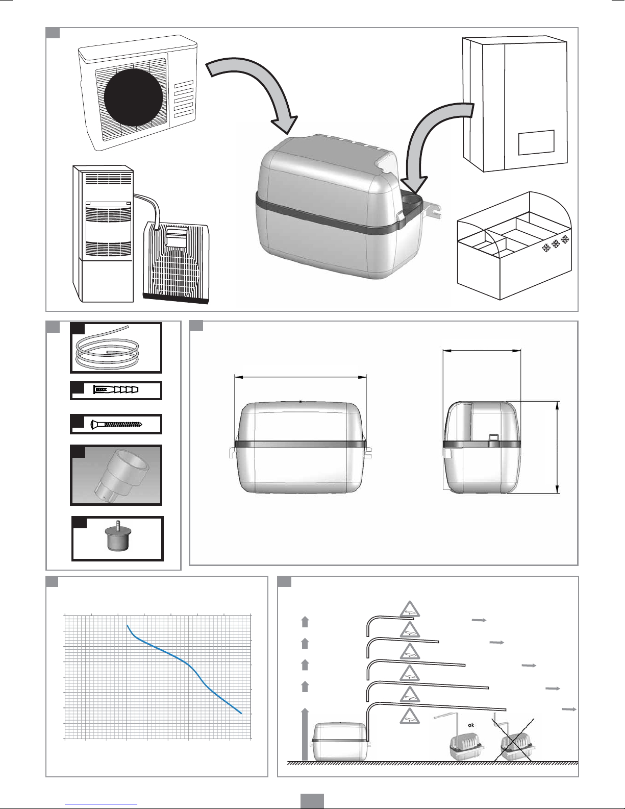
3
DIMENSIONS:
see fig.3
4
SANICONDENS®AREA OF APPLICATION AND
TECHNICAL DATA
Application Air conditioning systems, boilers,
refrigeration units
Type CD10
Max. vertical pumping 15 Ft (4.5 m)
Maximum flow rate (gal / hour) 86 (326 l/h)
Min. pH 2.5
Voltage 110-115 V
Frequency 60 Hz
Power rating 60 W
Current consumption 1.5 A
Electrical class I
Protection index IP20
Sound level <45 dBA
Maximum allowable temperature 160° F (70° C)
S3 15% (1min30 ON, 8min30 OFF)
Net weight 4.5 lbs
Tank volume 2 liters
Supply cable 6 Ft (2 m)
Discharge hose 20 Ft (6 m)
Alarm cable (3 core) 6 Ft (2 m)
Wall fastening Yes
CAUTION:
All applications other than those described in this notice are
prohibited.
5
PERFORMANCE CURVES:
see fig.5
6
VERTICAL PUMPING/HORIZONTAL PUMPING:
see fig.6
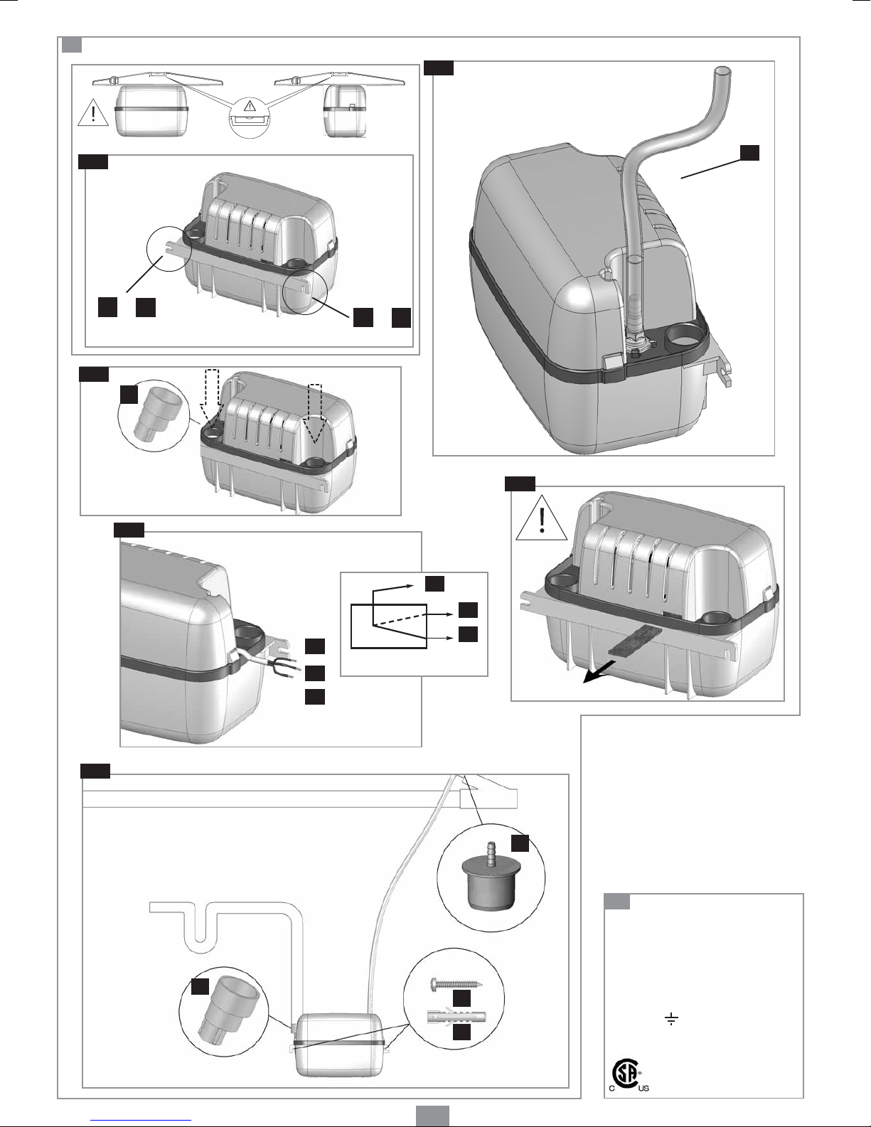
7
INSTALLATION
SANICONDENS®may be mounted on a wall by using the
mounting tabs on the tank..
The unit should be easy to access for testing and
maintenance.
The unit must be installed leveled. Adjust the
installation using a level before mounting the unit.
Make sure that the equipment is protected from damp while
installing it.
7b CONNECTING TO THE DISCHARGE PIPE
The SANICONDENS®discharge pipe must be connected to
the flexible hose A(supplied : length 20 Ft). This hose should
be used to form the vertical section of the discharge pipe.
• Place the flexible hose onto the non-return valve of the
SANICONDENS®(see diagram 7b).
• Position the flexible hose in the most vertical position
possible to avoid it kinking.
• It is advisable to make a smooth bend to avoid the hose
from kinking.
• The discharge vinyl tubing (included) can be connected to
a PVC line large in diameter by using the plastic reducer
Ythat is provided with the system.
As shown on the fig. 7f , the plastic fitting connects to the
end of the 3/8” vinyl tubing at the top and it increases the
diameter to ease the connection to a PVC line. (Reducer
is 3/8” barbed x 3/4" male end)
The SANICONDENS®is fitted with a non-return valve to
prevent re-activation.
ELECTRICAL CONNECTION
1. The electrical installation should be carried out by a qualified
person. The unit should be connected to a fully grounded
electrical supply. The SANICONDENS®requires a 120V
single phase AC 60 Hz supply.
7c CONNECTION AT THE COVER INLET
The unit has 2 inlets 1" in diameter (1 on each side - see fig.
7a). To connect the water to be drained off, connect the
water inlet to one of the inlets. If necessary, use the adapter
X(3/4”, 1-1/4”, 1-1/2” in diameter).
7d ALARM
SANICONDENS®is fitted with a detection system
that can trigger an alarm if the water level rises too high
(audible or visual alarm, 1.5V to 120V), see diagram 7d:
1. Brown wire: shared wire
2. Black wire: normally off
3. Blue wire: normally on
To fit the alarm, connect the blue and brown wires
of the alarm to the respective terminals on the
SANICONDENS®.
US CDN
INSTRUCTIONS INTENDED SOLELY FOR
QUALIFIED PROFESSIONALS
9420 249 SANICONDENS.indd 49420 249 SANICONDENS.indd 4 05/04/11 11:0305/04/11 11:03

5
8STANDARDS
This model is eligible to bear the CSA mark shown with
adjacent indicators “C” and “US”. The “C” and “US”
indicators adjacent to the CSA mark signify that the product
has been tested according to the applicable CSA (CDN)
and ANSI/UL standards for use in Canada and the USA.
This includes products eligible bear the designation NTRL.
NTRL (Nationally Recognized Testing Laboratory) is a desi-
gnation awarded by the American Occupational Safety and
Health Administration (OSHA) to laboratories authorized to
award the certification according to American standards.
11
LIMITED WARRANTY
This SFA appliance bears a 3 year warranty starting from
the date of purchase, subject to proper installation and use,
in compliance set out in this notice.
Warranty issues will be handled by the Technical Department
and will be subject to correct installation and usage.
If a replacement is to be issued, this will be only extended
to the first 180 days starting from the date of purchase
and will need to be approved by one of our company’s
representative. Warranty repairs will apply after such date
up to the warranty’s date of conclusion.
Plumber’s invoices for any type of repair, disconnection and
reconnection are not covered by the warranty and are the
end user’s responsibility. In no event shall the company be
liable for any special, incidental or consequential damage,
loss or injury of whatsoever nature or kind arising from or in
connection with the product or any component thereof.
10
TROUBLESHOOTING
Disconnect the electrical supply before carrying out any work.
FAULT DETECTED
• The pump does not start
• The pump does not lift
PROBABLE CAUSES
• The pump is not
connected to the power
supply
• The locking pin has not
been removed.
• The unit is not level.
• Power cut
• Float blocked
• Condensates inlet pipe
blocked
• Non-return valve blocked
• Discharge pipe blocked
ACTION NEEDED
• Plug in the unit.
• Remove the locking pin.
• Please check the unit
with a spirit level.
•
Check the mains voltage.
• Clean the SANICONDENS®
tank
.
• Clean the SANICONDENS®
inlet pipe
.
•
Clean the valve.
• Clean the discharge pipe
.
INSTRUCTIONS RESERVED SOLELY FOR
QUALIFIED PROFESSIONALS
OPTIONAL: if you connect the brown and black wires to
the control relays on your boiler, it will be switched off if the
water level rises too high in the unit.
ATTENTION: The maximum current admissible for our
detection system is 0.5A.
To protect the electrical components in the
SANICONDENS®, once the alarm has been triggered, any
water continuing to fill the tank comes out through the over-
flow outlets in the cover.
BEFORE TURNING THE DEVICE ON, MAKE
SURE YOU REMOVE THE PROTECTIVE LOCKING PIN
FROM THE REAR OF THE DEVICE
7f EXAMPLE OF AN INSTALLATION OF
A SANICONDENS®: see fig. 7f
9
DISASSEMBLY
If a breakdown occurs, any service on the unit should be
carried out by a qualified technician. In particular the
replacement of the power cable.
Disconnect the electrical supply before carrying out
work on the unit.
INSTRUCTIONS INTENDED SOLELY FOR
QUALIFIED PROFESSIONALS
7e
9420 249 SANICONDENS.indd 59420 249 SANICONDENS.indd 5 05/04/11 11:0305/04/11 11:03
Other manuals for SANICONDENS
1
Table of contents
Languages:
Popular Dryer manuals by other brands


ffuuss
ffuuss eos user manual

KitchenAid
KitchenAid 53-3498 installation instructions

Schulthess
Schulthess Spirit topLine TW 8340 operating instructions

Whirlpool
Whirlpool LGR4624BW0 parts list

World Dryer
World Dryer AirMax D M5-972A manual

Alliance Laundry Systems
Alliance Laundry Systems ADEE9BSS user guide


