SGS electronic TVC-TRF-10-MBT User manual
TVC-TRF-10-MBT
1
© SGS electronic 2006-2021
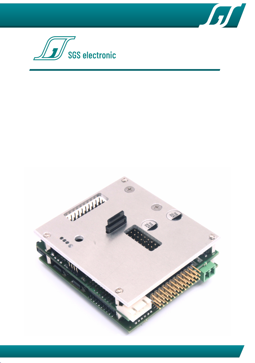
TVC-TRF-10-MBT
Full option module with sound for RC-battle tanks in
1/16th to1/25th scale
This module was developed to enable complete control of battle tanks.

TVC-TRF-10-MBT
2© SGS electronic 2006-2021
1 Note
Installation of the module requires intermediate to advanced modeling skills.
Soldering skills are required to connect the wiring. Inexperienced modelers and
persons under 16 should seek the assistance of an experienced modeler.
Always switch off power when working on the wiring.
Especial take care when connecting more than one receiver energy source.
Prevent the device from getting wet.
Check loads before connecting them to the modul at a current limited, or
fuse protected source.

TVC-TRF-10-MBT
3
© SGS electronic 2006-2021
Contents
1 Note 2
2 Introducing 6
2.1 FOmodulfeatures............................ 6
2.2 technology ................................ 7
2.3 scopeofdelivery............................. 7
2.4 accessories ................................ 7
2.5 Overview.................................. 7
2.5.1 build in functions . . . . . . . . . . . . . . . . . . . . . . . . 7
2.5.2 Additional options . . . . . . . . . . . . . . . . . . . . . . . 8
2.6 Radiorequirements ........................... 9
2.6.1 usableradios........................... 9
2.6.2 bestpractice........................... 9
3 functions 11
3.1 Manualcontrol.............................. 11
3.1.1
Channel 1 - Proportional left/right with integrated V-mixer
11
3.1.2 Channel 2 - Proportional forward/reverse . . . . . . . . . 11
3.1.3 Channel 3 - Proportional cannon elevation / gun trigger 11
3.1.4 Channel 4 Proportional turret rotation . . . . . . . . . . . 11
3.1.5 Channel 5 Controlling the light mode . . . . . . . . . . . . 12
3.1.6
Channel 6 turn model off / change model / activate turret
stabilization ........................... 12
3.1.7 Channel 7 Controlling the volume . . . . . . . . . . . . . . 12
3.1.8 Channel 8 firing . . . . . . . . . . . . . . . . . . . . . . . . . 12
3.2 Function of the light mode control . . . . . . . . . . . . . . . . . . 13
3.2.1 Lightmode1........................... 13
3.2.2 Lightmode2........................... 14
3.2.3 Tip2................................ 15
3.3 Automaticfunctions........................... 15
3.3.1 cannon .............................. 15
3.3.2 MG................................. 15
3.3.3 automatic engine stop . . . . . . . . . . . . . . . . . . . . . 15
3.4 drive-dynamic functions . . . . . . . . . . . . . . . . . . . . . . . . 16
3.4.1 Exhaust simulation module . . . . . . . . . . . . . . . . . . 16
3.4.2 Reverselight........................... 16
3.4.3 Rotating flasher light . . . . . . . . . . . . . . . . . . . . . . 16
3.4.4 Turnsignals ........................... 16

TVC-TRF-10-MBT
4© SGS electronic 2006-2021
3.4.5 Brakelight ............................ 17
4 Connector overview 18
4.1 Connection of batteries cable (X60) . . . . . . . . . . . . . . . . . . 18
4.2 connection to the receiver (X50 to X511) . . . . . . . . . . . . . . 19
4.3 connection of the servo outputs (X40 to X47) . . . . . . . . . . . . 20
4.3.1 Connect the turret turn servo . . . . . . . . . . . . . . . . . 20
4.3.2 Connect the cannon elevation servo . . . . . . . . . . . . . 21
4.3.3 Connect the recoil servo . . . . . . . . . . . . . . . . . . . . 21
4.4 connection of the motors (X01 - X04 & X20 - X21) . . . . . . . . . 21
4.5 connection of drive motors . . . . . . . . . . . . . . . . . . . . . . . 22
4.5.1 Connect the turret turn motor . . . . . . . . . . . . . . . . 22
4.5.2 Connect the cannon elevation motor . . . . . . . . . . . . 22
4.6 connection of the switch outputs (X08 to X17) . . . . . . . . . . . 22
4.6.1 Connection of lighting and exhaust systems . . . . . . . . 23
4.7 Connecting the speaker (X70) . . . . . . . . . . . . . . . . . . . . . 24
4.8 Connecting the battle unit (X510 and X511) . . . . . . . . . . . . . 25
5 Initialization 27
5.1 turnonsequence ............................ 27
5.2 operationmodes............................. 27
6 changing sound and software 28
6.1 Changingthesound........................... 28
6.2 Changing the software . . . . . . . . . . . . . . . . . . . . . . . . . 29
6.3 Battleunit ................................. 29
6.3.1 Vulnerably ............................ 29
6.3.2 Resetting the damage grade . . . . . . . . . . . . . . . . . 30
7 Practical tips 32
7.1 Neutralposition ............................. 32
7.2 Failsafereceiver ............................. 32
7.3 Do not use provisionally methods of connectivity . . . . . . . . . 32
7.4 Workonthewiring ........................... 32
7.5 Rotatingflasher ............................. 33
7.6 ConnectingLED ............................. 33
8 Glossary of terms 35
9 Technical data 36
10 Important 37

TVC-TRF-10-MBT
5
© SGS electronic 2006-2021
10.1Address .................................. 37
10.2Contact .................................. 37
10.3Documentdate.............................. 37
List of Figures
1 connectoroverview ........................... 18
2 battery cable shown with polarity . . . . . . . . . . . . . . . . . . . 19
3 servo connector signals . . . . . . . . . . . . . . . . . . . . . . . . . 19
4 orientation servo input cables to the receiver . . . . . . . . . . . . 19
5 Futaba servos have a plastic nozzle that has to be removed . . . 20
6 orientation servo output cables . . . . . . . . . . . . . . . . . . . . 20
7 example mechanic tor recoil and elevation . . . . . . . . . . . . . 21
8 motorconnectors ............................ 22
9 switchoutputs .............................. 23
10 speakerconnector............................ 24
11 TVC-BU12................................. 25
12 TVC-HRF-AD3 Heng Long adapter mounted on the FO module . 26
13 position and orientation of the µSD card slot . . . . . . . . . . . . 28
14 rotating flasher wiring . . . . . . . . . . . . . . . . . . . . . . . . . . 33
15 LEDresistor................................ 34
16 resistor for LED groups . . . . . . . . . . . . . . . . . . . . . . . . . 34
List of Tables
1
Overview control channels. abbrevations refer to table 9 on page
35. ..................................... 13
2 Lightmode1 ............................... 13
3 Lightmode2 ............................... 14
4 overview turret connections . . . . . . . . . . . . . . . . . . . . . . 21
5 Allocation of terminal posts for the lights, exhaust fan, and heater 24
6 boot-loader error codes . . . . . . . . . . . . . . . . . . . . . . . . 29
7 vulnerably depending on model type . . . . . . . . . . . . . . . . 30
8 delay used by the battle unit . . . . . . . . . . . . . . . . . . . . . . 31
9 Abbrevation for the manipulators in the transmitter housing . . 35

TVC-TRF-10-MBT
6© SGS electronic 2006-2021
2 Introducing
This modul for recovery tanks is based on our 3th generation of the full option
modul. This module comes with a wide range of in- and outputs and is therefore
suitable for a wide varety of models. The user can switch the function between
any of the model types just by loading the software provided on our website
• Trucks
trailer trucks
tank transporter trucks
spezial function trucks
• construction machines
dumper trucks
hydraulic excavators
rope excavators
dozers
• tanks
main battle tanks mbt/pso
recovery tanks
anti aircraft tanks
armored person carrier
excavator tanks
amphibious tanks
• snow forming tracked vehicles
• tugs
2.1 FO modul features
•
6 integrated ESC with a drive capability of 2x10A and 4x3A, clocked with
16kHz
•
audio subsystem with 15W amplifier , volume can be controlled by a
trimmer or a rc chanel
• 20 light output chanels
• 8 servo outputs
• 4 inputs for sensors (e.g. gepard radar parking pos sensor)
• maximum control chanel count is 16; PPM, S-Bus, I-Bus are supported
•
sounds and firmware can be loaded using a uSD card to change the

TVC-TRF-10-MBT
7
© SGS electronic 2006-2021
modules function to all kind of model software we provide
2.2 technology
The controller is rated for an input of 7.2V to 16V. A 10A fuse protects the
module and the battery from over current. Integrated fail safe functions prevent
unintended operation of the model.
An internal BEC generates 5V to supply the receiver. The receiver is supplied
through the servo cables. The modul internally operates with 3.3V.
2.3 scope of delivery
Connecting cables and plugs are supplied with the module, which must be
connected/soldered on the load side:
• servo leads for receiver connection
• green connector for power supply X60
• black connector for speaker X70
• black connectors for X01 to X04, X20 and X21
2.4 accessories
Connecting cables for outputs X08 to X17 (light, smoke generator, etc.) are NOT
included in the delivery. These outputs can be used with standard three-pin
servo leads. We offer different contacting options for this in the accessories.
•FO-LS10
universal cable set with 8 servo leads, cable ties and 8 series
resistors for LED
•FO-AD13 universal adapter with contact spring force clamps
•TVC-TRF-AD4
Adapter for connectors of the electrical system in Tamiya
truck models
2.5 Overview
2.5.1 build in functions
This module will provide the following functions:

TVC-TRF-10-MBT
8© SGS electronic 2006-2021
• proportional drive motor control with mixing
•
proportional turret rotation with servo output or integrated speed con-
troller
•
proportional barrel elevation with servo output or integrated speed con-
troller
• cannon fire and recoil with strobe LED flash and motor or servo output
• MG-LED
•
polyphonic sounds for all functions (including motor , MG, turret rotation,
gun)
• random sounds
•
automatic control of brake light, reverse light, flashing light, light control
can be changed by RC-channel
• battle-unit function (Tamiya compatible)
•
model change (up to three models can be controlled with one transmitter)
• automatic control of smoke pump and heating element
2.5.2 Additional options
With an additional module, TVC-GSU12, the turret can be stabilized in horizontal
and vertical direction.
For endless turret rotation, wiring can be eliminated by using GFMC-SBR10
scalebus repeater. In this case the turret drives and lights are connected to TVC-
GSU-12 (with stabilization) or turret control TVC-TC12 (without stabilization).

TVC-TRF-10-MBT
9
© SGS electronic 2006-2021
2.6 Radio requirements
2.6.1 usable radios
All common FM and 2.4GHz RC radios are supported. No special functions or
mixers are required in the transmitter. The simpler the radio, the easier the
commissioning.
In order to be able to control as many variants as possible, some functions of
the FO module work by storing operation modes or by differentiate the speed
of with which the stick is moved from the middle position.
For channels operating this way it is important that they are triggered starting
from the middle position.
This is for non-self-resetting channels, like
1. linear knobs
2. rotary knobs
3. non self centering sticks (throttel chanel for RC planes)
not automatically the case. An operation of the above functions should be done
with
1. three stage momentary switch
2. self centering sticks
.
In table 1 you can find the suggest kind of control elements for each chanel.
Note
Not self centering control elements must be placed in mid position
befor turning on the FO Modul.
2.6.2 best practice
We recommend testing the channels of your radio before installing the module.
Most radios today have their focus on operating RC planes. Control elements
are often not (all) intended to directly output their switching state. Their primary
task in flight radios is to manipulate the function / parameters of the mixers
built into the transmitter.
The failsafe function (if available) should be set to output the mid position
of all chanels.

TVC-TRF-10-MBT
10 © SGS electronic 2006-2021
The transmitter should not be set on the FO module. The servo travel in-
dicator on the transmitter display is more suitable, or a test setup with servos
connected directly to the receiver.
You can observe the following behavior:
1.
on a self centering stick a servo follows the movement of the stick. If you
let the stick go, the servos moves to mid position.
2.
having a linear or rotary knob on the chanel a servo follows the movement
and stays their even after untouching the control element
3.
with a three stage switch a servo can be moved to three positions. left,
mid, right. As the switch don’t move if you let him go, the servo will not
move also.
4.
using a three stage momentary switch a servo can also the moved to three
positions, mut it returns to mid after releasing the switch.

TVC-TRF-10-MBT
11
© SGS electronic 2006-2021
3 functions
3.1 Manual control
A proportional radio transmitter is required. It needs at least four channels and
at most seven channels. The use of channel 5, 6 and 7 is optional. The functions
of the channels are the following:
We use the term channel. This does not mean, that channel one of the
modul must be connected to channel 1 of your receiver. You are free to assign
the channels according to your preferences.
3.1.1 Channel 1 - Proportional left/right with integrated V-mixer
The integrated mixer slows the inside track to a full stop. Deflection of the stick
while stopped causes the vehicle to pivot steer. (This channel provides turn
signal information)
3.1.2 Channel 2 - Proportional forward/reverse
This channel also provides the information for brake and reverse lights, and
smoke generator.
3.1.3 Channel 3 - Proportional cannon elevation / gun trigger
With rapid stick operation to full deflection the MG (upper limit) or the primary
weapon (lower limit) is fired. For the MG a lamp/LED flickers to the sound, for
the main gun an LED is flashed. For the main gun a motor output is switched,
and an LED flashes. Recoil is also simulated with rapid retreat and slow return
of a servo output. Combied elevation/gun trigger on channel 3 is inactive, if
the dedicated trigger channel 8 is used. In this case channel 3 only moves the
gun vertically.
3.1.4 Channel 4 Proportional turret rotation

TVC-TRF-10-MBT
12 © SGS electronic 2006-2021
3.1.5 Channel 5 Controlling the light mode
Using this channel, the rotating flasher and the flasher can be controlled. In
addition there are two lamp outputs that can be used for individual switch
functions, e.g. light or beamers lamps. If this channel remains unplugged, all
outputs are turned off. The rotating flasher outputs are only active if a BattleUnit
hit happens and the outputs for the flashers become active when turning the
model left/right.
3.1.6 Channel 6 turn model off / change model / activate turret stabilization
Case the model is switched off by leaving the neutral position, the model stops
running when channels 1 to 5 are controlled and the engine off sound is played.
This feature can be used to play the engine start/stop sound by the RC. But
it can be used to switch between up to three different models. To achieve
that, the appropriate model must be switched on, when the channel 6 switch is
positioned in a unique position. The module stores this position as „turn on“
position. When the switch leaves this position, the model becomes passive and
can not be moved. However, in this state it can still be fired by other tanks and
the model reacts by rumbling, hit indicator and incrementing the hit counter. To
do this you need receivers with the same channel crystals. When using 2.4GHz
receivers, they must be bound to the same transmitter.
Using this channel is optional.
3.1.7 Channel 7 Controlling the volume
If this channel is connected to a receiver, volume is controlled using this RC
channel. Otherwise the volume is controlled with Trimmer P1.
3.1.8 Channel 8 firing
To limit the channels need, firing and gun elevation is combinded on chanel 3.
If your radio has enough channels, you can trigger the gun with this dedicated
channel. In this case the double function of chanel 3 is deactivated and it is
only used for elevation control.

TVC-TRF-10-MBT
13
© SGS electronic 2006-2021
chanel plug optional radio function
1 X50 no StickS steering
2 X51 no StickS throttle
3 X52 no StickS cannon elevation and firing
4 X53 no StickS turret rotation
5 X54 yes TSMS light mode control
6 X55 yes TSS model select
7 X56 yes Poti volume control
8 X57 yes TSMS firing
Table 1: Overview control channels. abbrevations refer to table 9 on page 35.
3.2 Function of the light mode control
There are two light modes light mode 1 and light mode 2. They are controlled
indepentently with one RC chanel.
3.2.1 Lightmode 1
Lichtmode 1 for auxillary output 1 and 2. They can be used for combat light,
beam light or any other consumer.
for auxillary output 1 and 2. They can be used for combat light, beam light
or any other consumer. The mode is count up , (
1→2→3→4→1
and so
on). When keeping the stick for about 2 seconds, the lightmode is reset to 1(all
off).
Zustand 1 2 3 4
auxlight 1 off On off On
auxlight 2 off off On On
Table 2: Lightmode 1

TVC-TRF-10-MBT
14 © SGS electronic 2006-2021
3.2.2 Lightmode 2
The lightmode 2 controls the automatic functions of the warnblinker and the
rotating flasher. The lamp function is given by the table below. The modes are
called:
• road traffic 1
• road traffic 2
• road traffic 3
• combat 1
For example the turn flasher is not activated automaticly in combat mode, while
it is activated in road traffic 1 and 2 when steering.
The lightmode 2 is changed by tipping the stick backwards.The mode is
count up road traffic 1 → road traffic 2 → road traffic 3 → combat → road traffic
1, and so on. When keeping the stick for about 2 seconds, the lightmode 2 is
reset to ”road traffic1”.
Zustand road traffic
1
road traffic
2
road traffic
3
combat
brake light auto auto auto off
combat brake light off off off auto
blinker left and right auto auto
Warning
flasher
off
rotating light 1,2,3,4 off
on (rotating) on (rotating)
off
Table 3: Lightmode 2
The light modes states are stored when changing the operation mode. When
the model is switched off by the model selector channel, all light states are
unchanged.
When the model is parked by turning of the transmitter, all light are turned
off.
When using the battle-system, the four rotating lights are also activated in a
random way for about three seconds when the tank is hit by the battlesystem.

TVC-TRF-10-MBT
15
© SGS electronic 2006-2021
3.2.3 Tip 2
Typically, a three-stage switch is used on the transmitter. Proportional channels
with linear knops may complicate the selection of the light mode, because the
indexing is done by briefly returning to the center position. This may be difficult
with linear knops.
3.3 Automatic functions
3.3.1 cannon
When the cannon is fired, the following actions take place:
• the sound of the main gun is played
• the gun flash LED output is switched for about. 200milliseconds
•
the gun motor output is switched for about. 800 milliseconds. This output
can be used to trigger a barrel recoil unit with stop switch.
•
a servo output provides a rapid recoil and slow return to fire position. The
complete cycle must operate before firing the weapon again.
• there is a rumble in the drives
• the module transmits an infrared battle unit signal
3.3.2 MG
The MG light flashes at approximately two times per second when shooting
and the sound module plays the recorded MG sounds.
3.3.3 automatic engine stop
In case the radio is unoperated for about 2 minutes, the module turns off the
engine and plays the engine stop sound. Additional the exhaust simulation is
switched off. (parking mode)
To wake the module, just move the throttle stick, then the engine startup
sound will be played and all functions are available again.
When the module is parking mode, random sounds are played. E.g. this
can be sound from construction machines, music or walkie talky noise. These
sounds, like all others on the module, can be changed.

TVC-TRF-10-MBT
16 © SGS electronic 2006-2021
You can also change to the parking mode by turning off the radio. When
doing this, no random sound is played.
TIP
• If no warmstart sound can be found, the cold start sound will be played.
•
If you use a failsafe receiver, the receiver delivers signal output when
the radio is turned off. For that reason the module can not detect the
unpowered radio. Please turn off failsafe function or use a normal receiver.
3.4 drive-dynamic functions
3.4.1 Exhaust simulation module
The module will control a liquid smoke heater and pump/fan. The smoke
liquid heater is switched on when the model receives a valid radio signal. The
outputs for the blowers and pump are operated as a function of acceleration
and speed. At idle the smoke is inactive. As the model accelerates, smoke
increases proportional to setting and duration of the throttle. During steady
throttle travel the output is reduced by 50% (by means of PWM)
3.4.2 Reverse light
The reverse light output is linked to channel 2 and is automatic. As soon as the
throttle lever (channel 2) is in neutral or forward position is, the reverse light is
switched off.
3.4.3 Rotating flasher light
The flasher runs constantly with approx. 1.5 cycles per second. When signal
faults occur or when the transmitter is switched off the flasher stops.
3.4.4 Turn signals
Starting from a minimum of 10% throttle the signal lights will flash left or
right as required. Das Warnblinklicht kann durch den Lichtmodus 2 ein- oder
ausgeschaltet werden.

TVC-TRF-10-MBT
17
© SGS electronic 2006-2021
3.4.5 Brake light
The brake light is automatic. Lights go out automatically with resumed throttle.
TVC-TRF-10-MBT
18 © SGS electronic 2006-2021
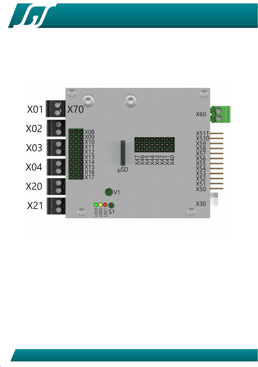
4 Connector overview
This section gives you an overview of the connectors. The exact function of
each connector can be found below.
Figure 1: connector overview
4.1 Connection of batteries cable (X60)
The connection is made with the green contact block. The connector is (X60). It
is a good practice to install a switch between battery and the power connector.

TVC-TRF-10-MBT
19
© SGS electronic 2006-2021
Fahrakku plus (+)
Fahrakku minus (-)
Figure 2: battery cable shown with polarity
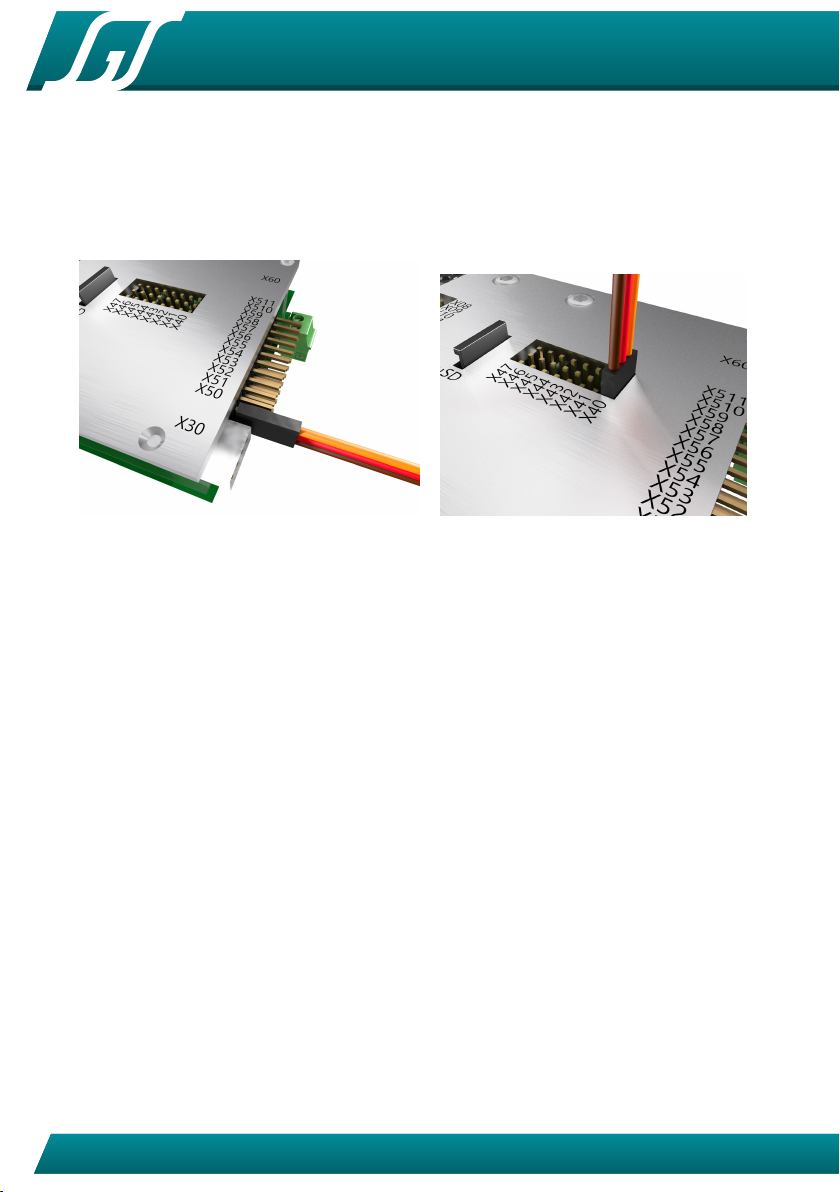
4.2 connection to the receiver (X50 to X511)
The connection to the receiver is made using jr patch cables. One side is plugged
into the module and one side is connected to the receiver.
picture 4 shows how the connectors are plugged into the module. The
ground (black or brown line of the servo cable) is closest to to the bottom of
the module. Most receivers have no mechanical polarity protection, so double
check polarity.
If the delivered cables does not match the length needed, they can simply
be replaced by longer or shorter versions.
Figure 3: servo connector signals
Figure 4: orientation servo input cables to the re-
ceiver
The module has an integrated BEC, so no additional BEC is needed. But if
you want to use one, or you have an additional ESC that has one integrated,
please do not operate your model with more than one BEC unit. This may lead
into damage if one of the BEC units is a switching voltage regulator (SBEC). In
this case pull the +5V (red( cable from all servo cables and isolate them with a
tape or shrink wrap.
TVC-TRF-10-MBT
20 © SGS electronic 2006-2021
4.3 connection of the servo outputs (X40 to X47)
The servos that are controlled by the module are connected to the connectors
X40 to X47. Picture 6 shows the orientation of the connector. The ground (black
or brown line of the servo cable) is closest to the center of the module.
Figure 5: Futaba servos have a plastic nozzle that
has to be removed
Figure 6: orientation servo output cables
The last servo position is stored with the module memory. Because of
that you do not have to expect bis servo moves when powering the module.
However, when powering the model, a short servo move may happen.
Make sure your servos can achieve the required position. When servo travel
is blocked current flow can be 300-500 mA instead of the usual 40mA at rest.
This can lead to hight temperatures of the module, because the BEC has to
deliver high currents.
Servo outputs that operate in parallel to a motor output behave like a gear
motor. Stick deflection results in rotation in proportion to motion. Release the
stick and the servo stops without returning to zero position. For that reason
only servos must be plugged in to this chanels. ESCs plugges to this channels
will not stop when returning to neutral, as most one would expect.
4.3.1 Connect the turret turn servo
Parallel to the esc output for turret rotation a servo output (X42) is controlled.
This simplifies control for models with small deflection like ”Jagdpanzer” or
Howitzer tanks. The servo functions are damped to provide realistic movements.
The speed and direction are proportional to stick deflection.
Table of contents
Other SGS electronic Control Unit manuals


Popular Control Unit manuals by other brands


CEL
CEL MeshConnect ZICM0868P0-1C Preliminary data sheet

cashco
cashco 521 Installation, operation & maintenance manual

CALEFFI
CALEFFI QuickSetter+ 132 Series manual

AMCI
AMCI SMD34E2 Frequently asked questions

Directed
Directed Directechs DB3 manual

Honeywell
Honeywell AlarmNet IGSMHS Installation and setup guide