SGS electronic TVC-TRF-10-MBT V2 User manual

TVC-TRF-10
(MBT V2)
Full option module with sound for RC-battle tanks
in 1 16th to1 25th scale
This module was developed to enable complete control of battle tanks.
This revised second edition of the module has been extended by the
following features:
–integrated battleunit
–polyphonic sound
–random sounds
–model change (up to three models can be controlled with one
transmitter)
–light control can the switched by RC
–automatic turn off
For different tanks there are versions available with sounds for::
#258120 HT1: Tiger 1 #258121 HT2: T-34
#258122 HT3: Panther #258123 HT4: Stug III
#258125 HT5: Panzer III
#258126 HT6: Walker Bulldog
#258102 MT1: Leopard 1 #258103 MT2: Leopard 2
#258107 MT6: Abrams #258110 MT9: T-55
instructions TVC-TRF-10-MBT_V2.odm Seite 1 von 29 Stand 13.10.11

Note:
Installation of the module requires intermediate to advanced
modeling skills Soldering skills are required to connect the wiring
Inexperienced modelers and persons under 16 should seek the
assistance of an experienced modeler
instructions TVC-TRF-10-MBT_V2.odm Seite 2 von 29 Stand 13.10.11

Overview:
This module will provide the following functions:
•proportional drive motor control with mixing
•proportional turret rotation with servo output and speed control
•proportional barrel elevation with servo output and speed control
•cannon fire and recoil with strobe LED flash and servo output
•MG LED
•polyphonic sounds for all functions (engine start stop idle,14 drive
stages, main gun, MG, turret turn, barrel elevation)
•automatic control of brake light, flashing light, rotating flasher
•battle-function
•model selection for up to three models
•automatic control of smoke pump and heating element
The controller is rated for an input of 7.2V to 12V. A 10A fuse protects
the module and the battery from over current. The module has 2
microprocessors with fail safe functions to prevent unintended operation
of the model.
The modul is equipped with a BEC circuit, that supplies the modul itself,
the receiver and the servos with a regulated 5V voltage.
scope of delivery:
–9 servo leads for X10 to X17 and/or X20 to X21
–speaker connection cable for X70
–connectors for X01, X02 and X60
–servo patch cable to connect the modul to the receiver
–10 resistors to connect LE
instructions TVC-TRF-10-MBT_V2.odm Seite 3 von 29 Stand 13.10.11

Function:
A proportional radio transmitter is required. It needs at least four
channels and max. six channels. The channels 5 and 6 can be plugged
optional. The functions of the channels are as follows:
Channel 1 - Proportional left right with integrated V-mixer. The
integrated mixer slows the inside track to a full stop. Deflection of the
stick while stopped causes the vehicle to pivot steer. (This channel
provides turn signal information)
Channel 2 - Proportional forward reverse. This channel also provides
the information for brake and reverse lights, and smoke generator.
Channel 3 - Proportional cannon elevation. With rapid stick operation to
full deflection the MG (upper limit) or the primary weapon (lower limit) is
fired. For the MG a lamp LED flickers to the sound, for the main gun an
LED is flashed. For the main gun a motor output is switched, and an
LED flashes. Recoil is also simulated with rapid retreat and slow return
of a servo output.
Channel 4 Proportional turret rotation
Channel 5 Controlling the light mode
Using this channel, the rotating flasher and the flasher can be controlled.
In addition there are two lamp outputs that can be used for individual
switch functions, e.g. light or beamers lamps.
If this channel leaves unplugged, all outputs are turned off. The rotating
flasher outputs are only active if a BattleUnit hit happens and the outputs
for the flashers become active when turning the model left right.
Channel 6 turn model of change model
Case the model is switched off by leaving the neutral position, the model
stops acting when channels 1 to 5 are controlled and the engine off
sound is played.
This feature can be used to play the engine start stop sound by the RC.
But it can the used to switch between up to three different models. To
archive that, the appropriate model must be switched on, when the
channel 6 switch is positioned in a unique position. The modul stores
this position as „turn on“ position. Leaves the switch this position, the
model becomes passive and can not be moved. However, in this state it
can still be fired by other tanks and model reacts to this by rumbling, hit
indicator and the hit counter increments.
instructions TVC-TRF-10-MBT_V2.odm Seite 4 von 29 Stand 13.10.11

To to this it is obvious, that you need receivers with the same channel
crystals. When using 2.4GHz receivers, they must be bound to the same
transmitter.
The use of this channel is optional.
Connection of the servo wires at the receiver
channe
l
connector optional Function
1 X50 no steering
2 X51 no throttle
3 X52 no cannon elevation and firing
4 X53 no turret rotation
5 X54 yes light mode control
6 X55 yes model select
channels 1 to 4 must be connected to the receiver, channel 5 and 6 can
be used optional.
instructions TVC-TRF-10-MBT_V2.odm Seite 5 von 29 Stand 13.10.11

Automatic functions:
Cannon:
When the cannon is fired, the following actions take place:
–the sound of the main gun is played
–the gun flash LED output is switched for about. 200milliseconds
–the gun motor output is switched for about. 800Milliseconds. This
output can be used to trigger a barrel recoil unit with stop switch.
–a servo output provides a rapid recoil and slow return to fire
position. The complete cycle must operate before firing the
weapon again.
–there is a rumble in the drives
–the modul transmits an infrared battle unit signal
MG:
The MG light flashes at approximately two times per second when
shooting and the sound module plays the recorded MG sounds.
instructions TVC-TRF-10-MBT_V2.odm Seite 6 von 29 Stand 13.10.11

automatic engine stop:
In case the radio is unoperated for about 2 minutes, the modul turns off
the engine and plays the engine stop sound. Additional the exhaust
simulation is switched off. (parking mode)
To wake the modul, just move the throttle stick, then the engine startup
sound will be played and all functions are available again.
When the modul is parking mode, random sounds are played. E.g. this
can be sound from construction machines, music or walkie talky noise.
These sounds, like all others on the modul, can be changed.
You can also change to the parking mode by turning off the radio. When
doing this, no random sound is played.
TIP:
If you use a failsafe receiver, the receiver delivers signal output when the
radio is turned off. For that reason the modul can not detect the
unpowered radio. Please turn off failsafe function or use a normal
receiver.
instructions TVC-TRF-10-MBT_V2.odm Seite 7 von 29 Stand 13.10.11

Automatic functions:
Exhaust simulation module:
The module will control a liquid smoke heater and pump fan . The
smoke liquid heater is switched on when the model receives a valid radio
signal. The outputs for the blowers and pump are operated as a function
of acceleration and speed. At idle the smoke is inactive. As the model
accelerates,smoke increases proportional to setting and duration of the
throttle. During steady throttle travel the output is reduced by 50% (by
means of PWM)
Reverse light:
The reverse light output is linked to channel 2 and is automatic. When
the throttle lever (channel 2) is in neutral or straight-ahead position the
reverse light circuit is turned off.
“Rotating” flasher light:
The flasher runs constantly at close to 1.5 cycles per second. The
flasher can be controlled by light mode 2.
Turn signals:
Starting from a minimum of 10% throttle the signal lights will flash left or
right as required. In lifting and clearing mode the light operate as hazard
lights. Because turn signal is not reasonable when digging, this
automatic function can be turned off, controlled by light mode 2.
Brake light:
The brake light is automatic. Lights go out automatically with resumed
throttle.
instructions TVC-TRF-10-MBT_V2.odm Seite 8 von 29 Stand 13.10.11
Installation:
Before installing the model it is best to connect the components on the
workbench. Familiarize yourself with the operation of the components.
Pay particular attention to the maximum travel of the servos.
You do not have to connect all loads. For basic operation it is sufficient
to power the modul and to connect all servo inputs that are not „optional“
to the receiver.
It is recommended to connect the speaker in this early state, because
you can hear the action that should be activated.
In the following section the position and orientation of the connectors are
explained. The exact function of each connector is described later in
detail.
instructions TVC-TRF-10-MBT_V2.odm Seite 9 von 29 Stand 13.10.11
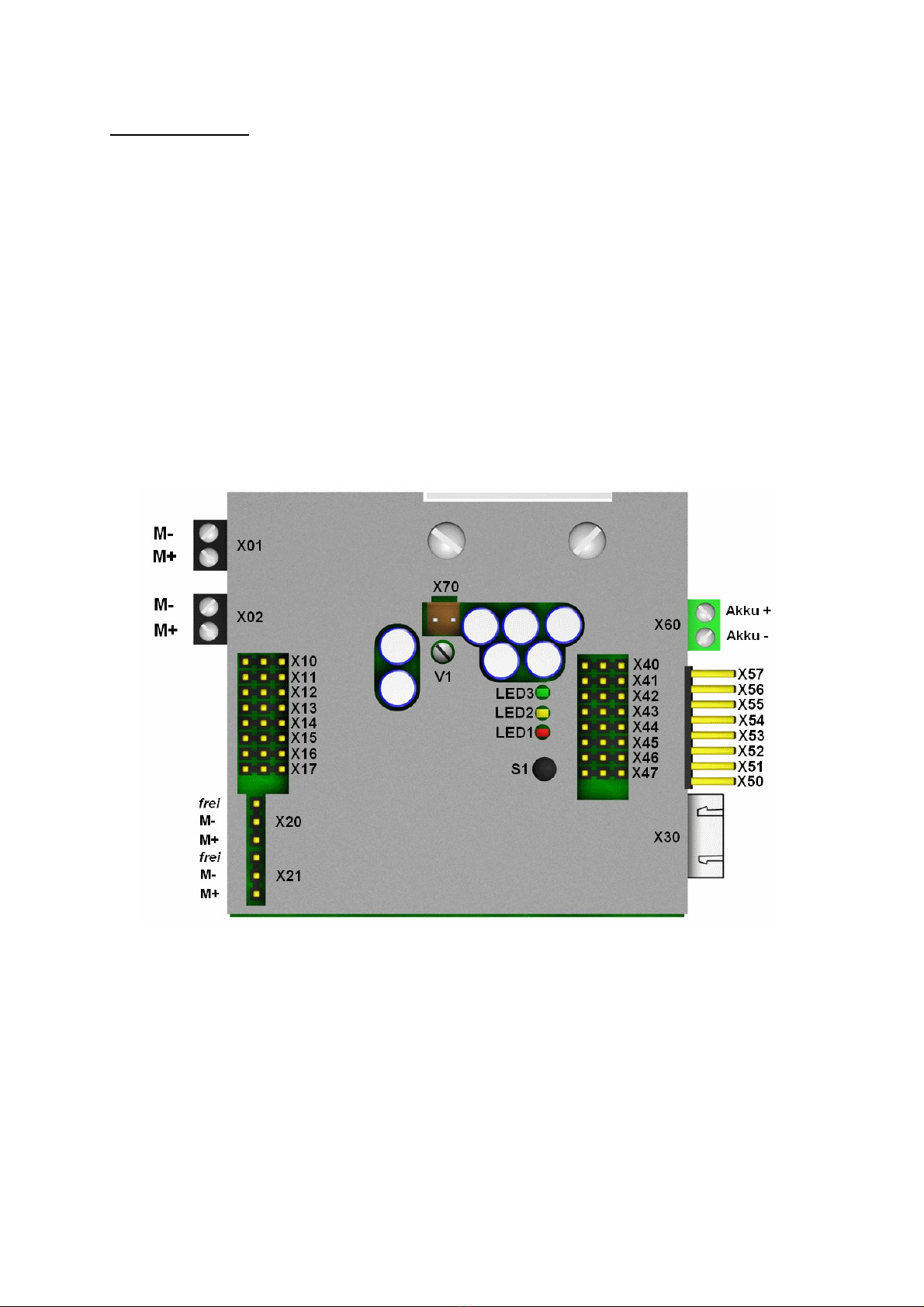
Abbildung 1: Connector Overview

connection of the servo inputs to the receiver (X50 to X57):
The connection to the receiver is
made using patch cables. One side
is plugged into the modul and one
side is connected to the receiver. If
the delivered cables does not match
the length needed, they can simply
be replaced by longer or shorter
versions.
The adjacent picture shows how the
connectors are plugged into the
modul.
The ground (black or brown line of
the servo cable) is closest to to the
bottom of the module.
connection of the servo outputs (X40 to X47):
The servos that are controlled by the
modul are connected to the
connectors X40 to X47.
Servos from Robbe Futaba or
Graupner JR can be connected
directly to the module. The ground
(black or brown line of the servo
cable) is closest to to the exterior of
the module.
The last servo position is stored with
the module memory. Because of that
you do not have to expect bis servo moves when powering the modul.
However, when powering the model, a short servo move may happen.
Make sure your servos can achieve the required position. When servo
travel is blocked current flow can be 300-500 mA instead of the usual
40mA at rest. This can lead to hight temperatures of the modul,
because the BEC has to deliver high currents.
instructions TVC-TRF-10-MBT_V2.odm Seite 10 von 29 Stand 13.10.11

connection of the motors (X20 and X21):
The motors that are connected to X20
and X21 leave the upper contact
unconnected.
connection of the switch outputs X10 to X17:
The switch outputs are used for light-
and simple motor functions. The
outputs are switched to ground (blue
and grey).
The left connection (red) is connected
to battery +. This is the same voltage
provided to the green connector. It is
protected by a fuse.
TIP: The left connection (permanent +) is the same for all eight
connectors. To reduce lead count, you can use one + for several loads.
instructions TVC-TRF-10-MBT_V2.odm Seite 11 von 29 Stand 13.10.11

Connection of batteries cable:
The connection is made with the green contact block. The connector is
(X60). It is a good practice to install a switch between battery and the
power connector. For your convenience you can choose our cable set
3013.
On the bottom side of the pcb are four fuses.
They protect the groups:
–speed controller (X01 and X02)
–speed controller (X20 and X21), switch outputs (X10 to X17)
–audioamplifier and cpu
–servo outputs (X40 to X47)
instructions TVC-TRF-10-MBT_V2.odm Seite 12 von 29 Stand 13.10.11
battery cable shown with polarity

Connection of drive motors:
The drive motors are attached to X01 and X02 at the black plug in
connectors. The motors must be properly radio-interference-suppressed
(install capacitors if required).
The motor outputs are marked so that when connecting the motor to +,
the corresponding chain run in forward direction. The best way to
connect the motors is as follows:
•prepare the model-chassis and a battery
•jack up the chassis
•connect the battery direct to the right motor. Mark the motor lead,
that must be connected to the positive pole of the battery, to run
the track in forward direction. Mark the positive lead with M+ and
the negativ lead with M-.
•do it the same way with the left motor
•connect the leads of the right motor to X01 as shown in the picture
obove.
•connect the leads of the left motor to X02 as shown in the picture
obove.
Case you have done so and the direction is still not correct, use the
servo reverse setting of you transmitter to fix it. Same for the steer
channel.
Note:
please don't confuse the servo leads connected to the throttle and the
steer channel.
instructions TVC-TRF-10-MBT_V2.odm Seite 13 von 29 Stand 13.10.11

Connect the turret and cannon elevation motor servos:
the turret rotation motor can be plugged to X21
the cannon elevation motor can be plugged to X20
The motor must be connected to the indicated terminals as per the
illustration.
In addition to these 2 motor outputs the Module provides 2 servo outputs
for turret rotation (X42) and cannon elevation (X41). These operate in
parallel to the motor outputs The servo functions are damped for
realistic movement results.
The servo is supplied by the integrated BEC. Servos from Robbe Futaba
or Graupner JR can be connected directly to the module. The
ground(black or brown Line of the servo cable) points to the exterior of
the Module. The speed and direction are proportional to stick deflection.
Connect the recoil servo:
The servo for the recoil is connected to X40
It is supplied by the integrated BEC. Servos from Robbe Futaba or
Graupner JR can be connected directly to the module. The ground(black
or brown Line of the servo cable) points to the exterior of the Module.
instructions TVC-TRF-10-MBT_V2.odm Seite 14 von 29 Stand 13.10.11
Abbildung 2: example for a recoil and elevation servo in one mechnical unit

Connecting the speaker:
The speaker connects at the brown 2 pole connector (X70) in the center
of the board. We recommend a 4 ohm speaker. An 8 or 16 ohm speaker
may be used but this will result in reduced sound volume. The volume
may be adjusted at the potentiometer (V1) directly below the connector.
The speaker needs to be installed in a box to prevent a feedback loop.
The presence of a box also improves bass response and sound
volume. The box should have as much volume as practical and should
not hinder airflow from the face of the speaker.
instructions TVC-TRF-10-MBT_V2.odm Seite 15 von 29 Stand 13.10.11
Connection of lighting and exhaust systems:
The lighting and exhaust system outputs are at battery voltage. evices
must be suitable for that voltage. If LE 's are used appropriate resistors
must be installed. These outputs can switch inductive loads such as
relays.
instructions TVC-TRF-10-MBT_V2.odm Seite 16 von 29 Stand 13.10.11
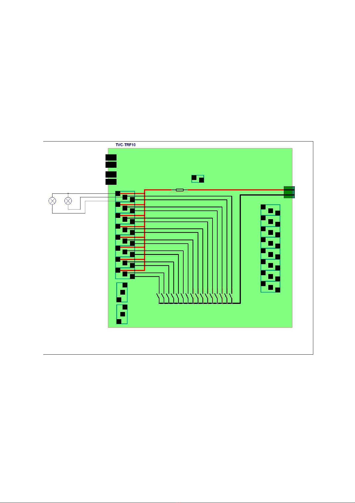
Illustration 3 connection diagram for lighting and smo e generator..

connector Left post Middle post Right post
X10 (+) MG LED (-)negative battery
terminal
(-) MG LED
X11 (+) rotating flasher 1+2 (-) rotating flasher 1 (-) rotating flasher 2
X12 (+) rotating flasher 3+4 (-) rotating flasher 3 (-) rotating flasher 4
X13 (+) cannon (-) cannon recoil (-) cannon LED
X14 (+) aux 1 and aux 2 (-) aux 1 (-) aux 2
X15 (+) reverse light and
brake light
(-) combat brake light (-) brake light
X16 (+) signal (-) signal left (-) signal right
X17 (+) Exhaust system (-)Exhaust system
heater
(-) Exhaust system
motor
Allocation of terminal posts for the lights, exhaust fan, and heater X10 to X17
instructions TVC-TRF-10-MBT_V2.odm Seite 17 von 29 Stand 13.10.11

Function of the light mode control
There are two light modes light mode 1 and light mode 2.
Lightmode 1 for auxillary output 1 and 2. They can be used for combat
light, beam light or any other consumer.
The lightmode 1 is changed by tipping the stick forward. The mode is
count up , 1 → 2 → 3 → 4 → 1, and so on.
When keeping the stick for about 2 seconds, the lightmode is reset to
1(all off).
light mode 1
state 1 2 3 4 1
auxlight 1 off On off On off
auxlight 2 off off On On off
The lightmode 2 controls the automatic functions of the warnblinker and
the rotating flasher. The lamp function is given by the table below.
The modes are called :
•road traffic 1
•road traffic 2
•road traffic 3
•combat 1
For example the turn flasher is not activated automaticly in combat
mode, while it is activated in road traffic 1 and 2 when steering.
The lightmode 2 is changed by tipping the stick backwards.The mode is
count up , road traffic1 → road traffic2 → road traffic3 → combat 1 →
road traffic1, and so on.
When keeping the stick for about 2seconds, the lightmode 2 is reset to
road traffic1.
instructions TVC-TRF-10-MBT_V2.odm Seite 18 von 29 Stand 13.10.11

light mode 2
state road traffic
1
road traffic
2
road traffic
3
combat
1
...
brake light auto auto auto off
combat brake light off off off auto
blinker left and
right
Auto
left right
Auto
left right
Warning
flasher
off
rotating light
off on
(rotating)
on (rotating) off
The light modes states are stored when changing the operation mode.
When the model is switched off by the model selector channel, all light
states are unchanged.
When the model is parked by turning of the transmitter, all light are
turned off.
TIP 1:
The four rotating lights are also activated in a random way for about
three seconds when the tank is hit by the battlesystem
TIP 2:
Typically, a three-stage switch is used on the transmitter.
Proportional channels with linear knops may complicate the selection of
the light mode, because the indexing is done by briefly returning to the
center position. This may be difficult with linear knops.
instructions TVC-TRF-10-MBT_V2.odm Seite 19 von 29 Stand 13.10.11
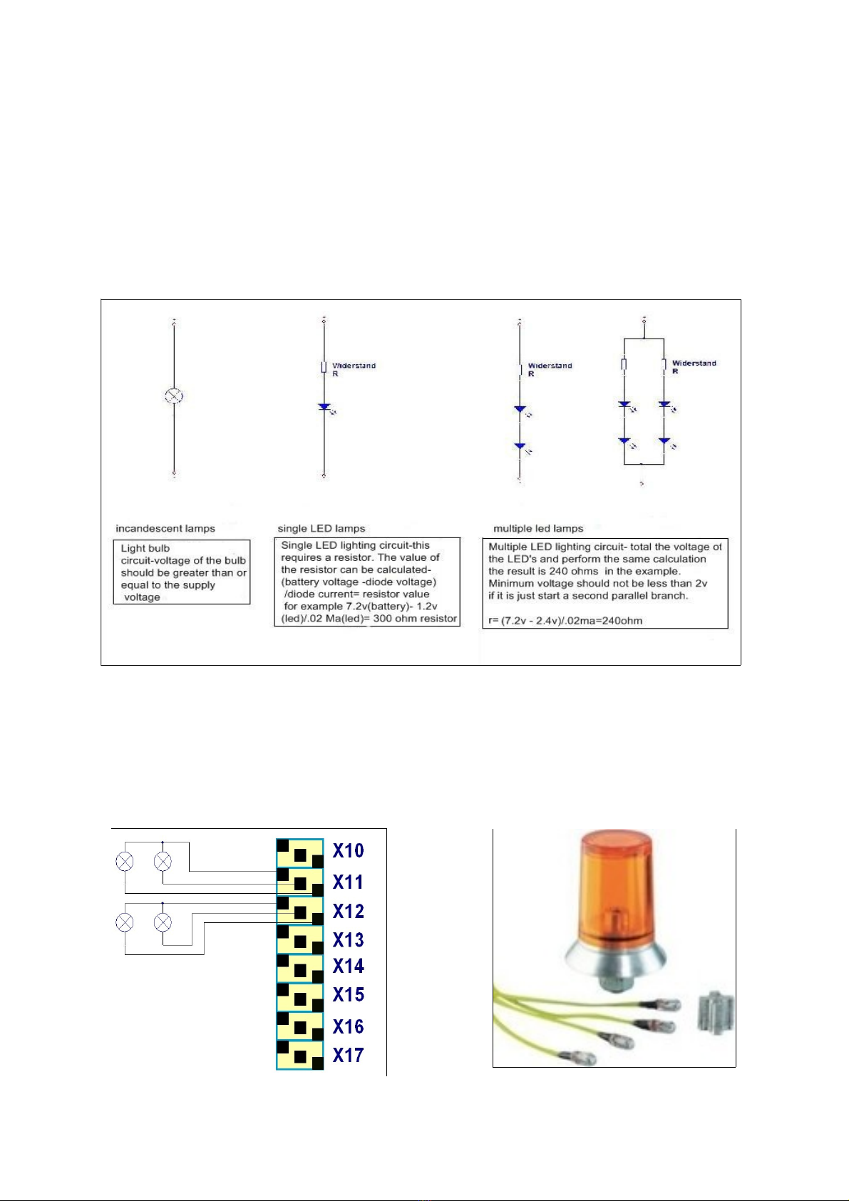
When connecting LED, please use suitable resistors. In the diagram
below the correct way to calculate the resistor value is show.
In any case you should connect the quite common resistors delivered
with the modul.
Note: Please never connect LED without resistor to the modul. This will
destroy the LED and or the modul.
Example: rotating flasher
The modul controls a rotating flasher with four lamps. Two lamps are
connected to X11 and two lamps are connected to X12.
Remember that the lighting outputs are at battery voltage. So when the
modul is powered with 12V the lamps must be rated for 12V.
l
instructions TVC-TRF-10-MBT_V2.odm Seite 20 von 29 Stand 13.10.11
Table of contents
Other SGS electronic Control Unit manuals


Popular Control Unit manuals by other brands


SMC Networks
SMC Networks VF1000 Series instruction manual

Parker Pneumatic
Parker Pneumatic CCJ1-1S Series Installation & service instructions

Pike
Pike RoboSign MK3 Operator's guide

Diehl
Diehl LoRaWAN CMi4160 user guide

Overland Tandberg
Overland Tandberg NEOxl 40 instructions

Elnec
Elnec DIL20W/PLCC20 ZIF manual