SGS electronic TVC-TRF-10-AAT User manual

TVC-TRF-10-AAT
1
© SGS electronic 2006-2021
TVC-TRF-10-AAT
Full option module with sound for RC-battle tanks in
1/16th to1/25th scale
This module was developed to enable complete control of Gepard Flak-
panzer. It can also control other modern air defense tracked vehicles such as
Roland or the Tunguskta (USSR).

TVC-TRF-10-AAT
2© SGS electronic 2006-2021
1 Note
Installation of the module requires intermediate to advanced modeling skills.
Soldering skills are required to connect the wiring. Inexperienced modelers and
persons under 16 should seek the assistance of an experienced modeler.
Always switch off power when working on the wiring.
Especial take care when connecting more than one receiver energy source.
Prevent the device from getting wet.
Check loads before connecting them to the modul at a current limited, or
fuse protected source.

TVC-TRF-10-AAT
3
© SGS electronic 2006-2021
Contents
1 Note 2
2 Introducing 6
2.1 FOmodulfeatures............................ 6
2.2 technology ................................ 7
2.3 scopeofdelivery............................. 7
2.4 accessories ................................ 7
2.5 Overview.................................. 7
2.5.1 build in functions . . . . . . . . . . . . . . . . . . . . . . . . 7
2.5.2 additional options . . . . . . . . . . . . . . . . . . . . . . . . 8
2.6 Radiorequirements ........................... 8
2.6.1 usableradios........................... 8
2.6.2 bestpractice........................... 9
3 function 11
3.1 manualcontrol.............................. 12
3.1.1 channel1............................. 12
3.1.2 channel2............................. 12
3.1.3 channel3............................. 12
3.1.4 channel4 ............................ 13
3.1.5 channel5............................. 13
3.1.6 channel6............................. 13
3.1.7 Channel 7 turn model off / change model . . . . . . . . . 14
3.1.8 Channel 8 Controlling the volume . . . . . . . . . . . . . . 14
3.2 Function of the light mode control . . . . . . . . . . . . . . . . . . 15
3.2.1 Tip................................. 16
3.3 Automaticfunctions........................... 16
3.3.1 35mmcanon........................... 16
3.3.2 MG................................. 16
3.3.3 searchradar ........................... 16
3.3.4 automatic engine stop . . . . . . . . . . . . . . . . . . . . . 16
3.4 drive-dynamic functions . . . . . . . . . . . . . . . . . . . . . . . . 17
3.4.1 Exhaust simulation module . . . . . . . . . . . . . . . . . . 17
3.4.2 Reverselight........................... 17
3.4.3 Rotating flasher light . . . . . . . . . . . . . . . . . . . . . . 17
3.4.4 Turnsignals ........................... 17
3.4.5 Brakelight ............................ 18

TVC-TRF-10-AAT
4© SGS electronic 2006-2021
4 Connector overview 19
4.1 Connection of batteries cable (X60) . . . . . . . . . . . . . . . . . . 20
4.2 connection to the receiver (X50 to X511) . . . . . . . . . . . . . . 20
4.3 connection of the servo outputs (X40 to X47) . . . . . . . . . . . . 21
4.3.1 Connect the turret and cannon elevation motor/servos . 22
4.3.2 Connection of targeting radar servos . . . . . . . . . . . . 23
4.3.3 Connection of search radar elevation servo . . . . . . . . 23
4.3.4 Connection of the park position sensor . . . . . . . . . . . 23
4.4 connection of the motors (X01 - X04 & X20 - X21) . . . . . . . . . 23
4.5 connection of drive motors . . . . . . . . . . . . . . . . . . . . . . . 23
4.6 connection of the switch outputs (X08 to X17) . . . . . . . . . . . 25
4.6.1 Connection of lighting and exhaust systems . . . . . . . . 25
4.7 Connecting the speaker (X70) . . . . . . . . . . . . . . . . . . . . . 26
5 Initialization 28
5.1 turnonsequence ............................ 28
5.2 operationmodes............................. 28
6 changing sound and software 29
6.1 Changingthesound........................... 29
6.2 Changing the software . . . . . . . . . . . . . . . . . . . . . . . . . 30
7 Practical tips 31
7.1 Neutralposition ............................. 31
7.2 Failsafereceiver ............................. 31
7.3 Do not use provisionally methods of connectivity . . . . . . . . . 31
7.4 Workonthewiring ........................... 31
7.5 Rotatingflasher ............................. 32
7.6 ConnectingLED ............................. 32
8 Glossary of terms 34
9 Technical data 35
10 Important 36
10.1Address .................................. 36
10.2Contact .................................. 36
10.3Documentdate.............................. 36

TVC-TRF-10-AAT
5
© SGS electronic 2006-2021
List of Figures
1 example radio stick assignment . . . . . . . . . . . . . . . . . . . . 11
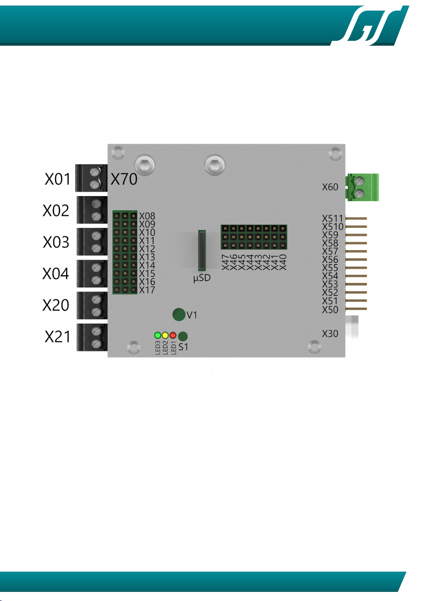
2 connectoroverview ........................... 19
3 battery cable shown with polarity . . . . . . . . . . . . . . . . . . . 20
4 servo connector signals . . . . . . . . . . . . . . . . . . . . . . . . . 21
5 orientation servo input cables to the receiver . . . . . . . . . . . . 21
6 Futaba servos have a plastic nozzle that has to be removed . . . 21
7 orientation servo output cables . . . . . . . . . . . . . . . . . . . . 21
8 motorconnectors ............................ 24
9 switchoutputs .............................. 25
10 speakerconnector............................ 26
11 position and orientation of the µSD card slot . . . . . . . . . . . . 29
12 rotating flasher wiring . . . . . . . . . . . . . . . . . . . . . . . . . . 32
13 LEDresistor................................ 33
14 resistor for LED groups . . . . . . . . . . . . . . . . . . . . . . . . . 33
List of Tables
1
Overview control channels. abbrevations refer to table 6 on page
34. ..................................... 14
2 lightmode ................................ 15
3 motor and servo outputs overview . . . . . . . . . . . . . . . . . . 22
4 Allocation of terminal posts for the lights, exhaust fan, and heater 26
5 boot-loader error codes . . . . . . . . . . . . . . . . . . . . . . . . 30
6 Abbrevation for the manipulators in the transmitter housing . . 34

TVC-TRF-10-AAT
6© SGS electronic 2006-2021
2 Introducing
This modul for recovery tanks is based on our 3th generation of the full option
modul. This module comes with a wide range of in- and outputs and is therefore
suitable for a wide varety of models. The user can switch the function between
any of the model types just by loading the software provided on our website
• Trucks
trailer trucks
tank transporter trucks
spezial function trucks
• construction machines
dumper trucks
hydraulic excavators
rope excavators
dozers
• tanks
main battle tanks mbt/pso
recovery tanks
anti aircraft tanks
armored person carrier
excavator tanks
amphibious tanks
• snow forming tracked vehicles
• tugs
2.1 FO modul features
•
6 integrated ESC with a drive capability of 2x10A and 4x3A, clocked with
16kHz
•
audio subsystem with 15W amplifier , volume can be controlled by a
trimmer or a rc chanel
• 20 light output chanels
• 8 servo outputs
• 4 inputs for sensors (e.g. gepard radar parking pos sensor)
• maximum control chanel count is 16; PPM, S-Bus, I-Bus are supported
•
sounds and firmware can be loaded using a uSD card to change the

TVC-TRF-10-AAT
7
© SGS electronic 2006-2021
modules function to all kind of model software we provide
2.2 technology
The controller is rated for an input of 7.2V to 16V. A 10A fuse protects the
module and the battery from over current. Integrated fail safe functions prevent
unintended operation of the model.
An internal BEC generates 5V to supply the receiver. The receiver is supplied
through the servo cables. The modul internally operates with 3.3V.
2.3 scope of delivery
Connecting cables and plugs are supplied with the module, which must be
connected/soldered on the load side:
• servo leads for receiver connection
• green connector for power supply X60
• black connector for speaker X70
• black connectors for X01 to X04, X20 and X21
2.4 accessories
Connecting cables for outputs X08 to X17 (light, smoke generator, etc.) are NOT
included in the delivery. These outputs can be used with standard three-pin
servo leads. We offer different contacting options for this in the accessories.
•FO-LS10
universal cable set with 8 servo leads, cable ties and 8 series
resistors for LED
•FO-AD13 universal adapter with contact spring force clamps
•TVC-TRF-AD4
Adapter for connectors of the electrical system in Tamiya
truck models
2.5 Overview
2.5.1 build in functions
This module will provide the following functions:

TVC-TRF-10-AAT
8© SGS electronic 2006-2021
•
proportional drive motor control with two mixing integrated speed con-
trollers
• proportional turret rotation with servo output and speed control
• proportional barrel elevation with servo output and speed control
• tow servo outputs for targeting radar rotation and elevation
• servo output for deploying and stowing search radar
•
control of search radar (speed control) with sensing for stowage position
•
polyphonic sounds for all functions (engine start/stop/idle,14 drive stages,
main gun, MG, turret turn, barrel elevation)
• main gun fire with led strobe
• machine gun fire with strobe
• automatic control of brake light, reverse light, flashing light
• automatic control of smoke pump and heating element
• Volime control by RC or at the modul
2.5.2 additional options
Anti Aircraft tanks turn the turret much faster than e.g. battle tanks. Therefore,
and because there are much more wires, the wiring between turret and hull is
challenging. To reduce the wire count, the modul TVC-TC13 can be used. All
control signals from the FO-modul in the hull to the turret are concentrated
on the SCALEBUS. This reduces the wire count from 15 to only 4. This lines
can be feed using a rotary feedthrough. To remove all wire connections two
SCALEBUS-Infrared-repeaters, GFMC-SBR10, can be used.
2.6 Radio requirements
2.6.1 usable radios
All common FM and 2.4GHz RC radios are supported. No special functions or
mixers are required in the transmitter. The simpler the radio, the easier the
commissioning.
In order to be able to control as many variants as possible, some functions of
the FO module work by storing operation modes or by differentiate the speed
of with which the stick is moved from the middle position.
For channels operating this way it is important that they are triggered starting

TVC-TRF-10-AAT
9
© SGS electronic 2006-2021
from the middle position.
This is for non-self-resetting channels, like
1. linear knobs
2. rotary knobs
3. non self centering sticks (throttel chanel for RC planes)
not automatically the case. An operation of the above functions should be done
with
1. three stage momentary switch
2. self centering sticks
.
In table 1 you can find the suggest kind of control elements for each chanel.
Note
Not self centering control elements must be placed in mid position
befor turning on the FO Modul.
2.6.2 best practice
We recommend testing the channels of your radio before installing the module.
Most radios today have their focus on operating RC planes. Control elements
are often not (all) intended to directly output their switching state. Their primary
task in flight radios is to manipulate the function / parameters of the mixers
built into the transmitter.
The failsafe function (if available) should be set to output the mid position
of all chanels.
The transmitter should not be set on the FO module. The servo travel in-
dicator on the transmitter display is more suitable, or a test setup with servos
connected directly to the receiver.
You can observe the following behavior:
1.
on a self centering stick a servo follows the movement of the stick. If you
let the stick go, the servos moves to mid position.
2.
having a linear or rotary knob on the chanel a servo follows the movement
and stays their even after untouching the control element
3.
with a three stage switch a servo can be moved to three positions. left,

TVC-TRF-10-AAT
10 © SGS electronic 2006-2021
mid, right. As the switch don’t move if you let him go, the servo will not
move also.
4.
using a three stage momentary switch a servo can also the moved to three
positions, mut it returns to mid after releasing the switch.

TVC-TRF-10-AAT
11
© SGS electronic 2006-2021
3 function
A proportional radio transmitter is required. It needs at least four channels and
max. eight channels. The channels 5,6,7 and 8 can be plugged optional.
To have maximum degree of freedom in controlling the turret, the module
can operate in three control modes that can be switched any time using one
channel on your RC. Using control mode 1 and 2, one stick is to control the tracks
and one stick is to control the semi automatic Gun and tracking radar. When
using control mode 3, one stick is to control the tracking radar independent of
the turret, using the second stick. The control mode is switched by a rc channel.
If this channel is unconnected, the module operates in control mode 2.
Figure 1: example radio stick assignment

TVC-TRF-10-AAT
12 © SGS electronic 2006-2021
3.1 manual control
Please note, we use the naming convention
channel
, but this does not mean,
that channel one of our module must be connected to your receiver channel
one. You are free in assignment.
3.1.1 channel 1
mode 1 and 2
Proportional left/right with integrated V-mixer The integrated
mixer slows the inside track to a full stop. Deflection of the stick while stopped
causes the vehicle to pivot steer. (This channel provides turn signal information)
mode 3 turret rotation proportional left/right
3.1.2 channel 2
mode 1 and 2 Proportional forward/reverse
This channel also provides the information for brake and reverse lights, and
smoke generator.
mode 3 barrel elevation proportional up/down
3.1.3 channel 3
Bei schneller Betätigung in die Maximalposition wird das MG (oberer Anschlag)
bzw. die Hauptwaffe (unterer Anschlag) ausgelöst. Für das MG flackert eine
Lampe/LED zum Sound, für die BKs wird eine LED angesteuert. Dies funktioniert
in allen Modi.
mode 1 barrel elevation and tracking radar proportional up/down.
The elevation of the targeting radar and the barrel elevation are move simulta-
neously. Additional a oscillating movement is added to the the tracking radar
movement.

TVC-TRF-10-AAT
13
© SGS electronic 2006-2021
mode 2 barrel elevation and tracking radar proportional up/down
The elevation of the targeting radar is directly operated; the gun carriage follows
as soon as the control stick is released.
mode 3 tracking radar proportional up/down
The elevation of the targeting radar is directly operated.
3.1.4 channel 4
mode 1 and 2
Turret rotation and targeting radar rotation proportional left/right
The targeting radar is steered directly until the turret blocks the view of the radar.
The turret follows the radar position as soon as the control stick is released.
This applies to small stick deflection. Greater stick deflection will operate the
turret directly. Please note that this is possible only with servo output the gear
motor output operates proportional to stick deflection(speed control).
mode 3
identical to control mode 1 and 2 but the turret rotation is controlled
separately
3.1.5 channel 5
Controlling the light mode
Using this channel, the rotating flasher, the
flasher can be controlled. In addition there are two lamp outputs that can
be used for individual switch functions, e.g. light or beamers lamps.
Controlling the search radar
The automatic radar exposing can be controlled
with this channel. This is also done automatic when the modell is switched of
by rc.
3.1.6 channel 6
This channel defines the control modes The three control modes change the
way the tracks, the turret and the tracking radar are controlled. The use of this
channel is optional. If it is not connected, control mode 2 is selected.

TVC-TRF-10-AAT
14 © SGS electronic 2006-2021
3.1.7 Channel 7 turn model off / change model
Case the model is switched off by leaving the neutral position, the model stops
running when channels 1 to 5 are controlled and the engine off sound is played.
This feature can be used to play the engine start/stop sound by the RC. But
it can be used to switch between up to three different models. To achieve
that, the appropriate model must be switched on, when the channel 7 switch is
positioned in a unique position. The module stores this position as „turn on“
position. When the switch leaves this position, the model becomes passive and
can not be moved. However, in this state it can still be fired by other tanks and
the model reacts by rumbling, hit indicator and incrementing the hit counter. To
do this you need receivers with the same channel crystals. When using 2.4GHz
receivers, they must be bound to the same transmitter.
Using this channel is optional.
3.1.8 Channel 8 Controlling the volume
If this channel is connected to a receiver, volume is controlled using this RC
channel. Otherwise the volume is controlled with Trimmer P1.
chan-
nel
plug op-
tional
ra-
dio
1 2 3
1 X50 no
StickS
steering steering turret rotation
2 X51 no
StickS
throttle throttle gun elevation
3 X52 no
StickS
cannon eleva-
tion, tracking
radar, elevation
and firing
cannon eleva-
tion, tracking
radar,elevation
and firing
tracking radar,
elevation and
firing
4 X53 no
StickS
turret rota-
tion, azimuth
tracking radar
turret rota-
tion, azimuth
tracking radar
azimuth track-
ing radar
5 X54 yes
TSMS
light mode control / search radar control
6 X55 yes
TSMS
control mode selection
7 X56 yes TSS model select
8 X57 yes Pot volume control
Table 1: Overview control channels. abbrevations refer to table 6 on page 34.

TVC-TRF-10-AAT
15
© SGS electronic 2006-2021
3.2 Function of the light mode control
With this channel the light control is put into different modes. In the different
light modes, the light outputs act like indicnonated in the table below. The light
is activated for the following scenarios:
• road traffic 1
• road traffic 2
• road traffic 3
• combat
• target practice
For example the turn flasher is not activated automatically in combat mode,
while it is activated in road traffic 1 and 2 when steering.
Sequence road
traffic 1
road
traffic 2
road
traffic 3
combat target
practice
brake light auto auto auto off auto
combat brake light off off off auto off
blinker left and right
auto
(left/right)
warning
flasher
auto
(left/right)
off
auto
(left/right)
rotating light 1,2,3,4 off
on (rotat-
ing)
on (rotat-
ing)
off
on (rotat-
ing)
light off off on off off
combat light off off off on off
Table 2: light mode
The lightmode is changed by tipping the stick. The mode is count up road
traffic 1 → road traffic 2 → road traffic 3 → combat → target practice → road
traffic 1, and so on. When keeping the stick for about 2 seconds, the lightmode
is reset to ”road traffic1”.
The light modes states are stored when changing the operation mode. When
the model is switched off by the model selector channel, all light states are
unchanged. When the model is parked by turning of the transmitter, all light
are turned off.
When the model is parked by turning of the transmitter, all light are turned
off.

TVC-TRF-10-AAT
16 © SGS electronic 2006-2021
3.2.1 Tip
Typically, a three-stage switch is used on the transmitter. Proportional channels
with linear knops may complicate the selection of the light mode, because the
indexing is done by briefly returning to the center position. This may be difficult
with linear knops.
3.3 Automatic functions
3.3.1 35mm canon
When the cannon is fired, the following actions take place:
• the sound of the main gun is played
• the gun flash LED output is flickering
3.3.2 MG
The MG light flashes at approximately two times per second when shooting
and the sound module plays the recorded MG sounds.
3.3.3 search radar
When the expose sequence is triggered, the search radar is deployed from its
stowed position. 1 second later the rotation motor is turned on. As soon as
it is commanded to return to the stowed position, Stowage requires a switch
to locate the correct position for the stowage sequence to commence. When
radar is stopped in position the controller waits 1 seconds and stows away.
3.3.4 automatic engine stop
In case the radio is unoperated for about 2 minutes, the module turns off the
engine and plays the engine stop sound. Additional the exhaust simulation is
switched off. (parking mode)
To wake the module, just move the throttle stick, then the engine startup
sound will be played and all functions are available again.
When the module is parking mode, random sounds are played. E.g. this
can be sound from construction machines, music or walkie talky noise. These

TVC-TRF-10-AAT
17
© SGS electronic 2006-2021
sounds, like all others on the module, can be changed.
You can also change to the parking mode by turning off the radio. When
doing this, no random sound is played.
TIP
• If no warmstart sound can be found, the cold start sound will be played.
•
If you use a failsafe receiver, the receiver delivers signal output when
the radio is turned off. For that reason the module can not detect the
unpowered radio. Please turn off failsafe function or use a normal receiver.
3.4 drive-dynamic functions
3.4.1 Exhaust simulation module
The module will control a liquid smoke heater and pump/fan. The smoke
liquid heater is switched on when the model receives a valid radio signal. The
outputs for the blowers and pump are operated as a function of acceleration
and speed. At idle the smoke is inactive. As the model accelerates, smoke
increases proportional to setting and duration of the throttle. During steady
throttle travel the output is reduced by 50% (by means of PWM)
3.4.2 Reverse light
The reverse light output is linked to channel 2 and is automatic. As soon as the
throttle lever (channel 2) is in neutral or forward position is, the reverse light is
switched off.
3.4.3 Rotating flasher light
The flasher runs constantly with approx. 1.5 cycles per second. When signal
faults occur or when the transmitter is switched off the flasher stops.
3.4.4 Turn signals
Starting from a minimum of 10% throttle the signal lights will flash left or
right as required. Das Warnblinklicht kann durch den Lichtmodus 2 ein- oder
ausgeschaltet werden.

TVC-TRF-10-AAT
18 © SGS electronic 2006-2021
3.4.5 Brake light
The brake light is automatic. Lights go out automatically with resumed throttle.
TVC-TRF-10-AAT
19
© SGS electronic 2006-2021
4 Connector overview
This section gives you an overview of the connectors. The exact function of
each connector can be found below.
Figure 2: connector overview
Please note that the direction of operation of each function is given by the
modul. While lights(blinker) and motors can easily be assigned by wiring , it is
not that easy for servos. In addition the servos parking positions are given by
the modul. Before mounting any servo into the model, chech the function on
your desktop and check carfully the operation direction. for channel 1 (steering)
:
• tracked drive directions
• blinker left/right
• turret rotation
• tracking radar left / right

TVC-TRF-10-AAT
20 © SGS electronic 2006-2021
for channel 2 (throttle):
• tracked drive directions
• brake and reverse light
• Gun elevation (up/down and parking position)
• tracking radar (up/down)
4.1 Connection of batteries cable (X60)
The connection is made with the green contact block. The connector is (X60). It
is a good practice to install a switch between battery and the power connector.
Fahrakku plus (+)
Fahrakku minus (-)
Figure 3: battery cable shown with polarity
4.2 connection to the receiver (X50 to X511)
The connection to the receiver is made using jr patch cables. One side is plugged
into the module and one side is connected to the receiver.
picture 5 shows how the connectors are plugged into the module. The
ground (black or brown line of the servo cable) is closest to to the bottom of
the module. Most receivers have no mechanical polarity protection, so double
check polarity.
If the delivered cables does not match the length needed, they can simply
be replaced by longer or shorter versions.
Table of contents
Other SGS electronic Control Unit manuals


