Nordelettronica NE205 11 User manual

KIT NE205_11KIT NE205_11
NE205_11NE205_11 NE206NE206 NE216_11NE216_11
NE198
NE198
IIISTRUZIONI D’USO
GBGB INSTRUCTIONS MANUAL
EEINSTRUCCIONES PARA EL USO
FFINSTRUCTIONS D’EMPLOI
DDBEDIENUNGSANLEITUNG
NE143PNE143P

22
33
FRANÇAIS
Schema d’installation......................... 4
Derivateur “NE205”................................. 11
Légende fusibles................................ 11
Fonctionnement................................. 11
Panneau de commande “NE216”............12
Descriptions....................................... 12
Alertes................................................ 12
Gérer les consommations.................. 12
Chargeur de batteries “NE143-P”........... 13
Description......................................... 13
Fonctionnement................................. 13
Profile de charge................................ 13
Attention............................................. 13
Caracteristiques techniques...............13
Protections......................................... 13
DEUTSCH
Installationsplan................................. 4
Abzweigdose “NE”205”........................... 14
Zeichenerklärung Sicherungen.......... 14
Betriebsweise.....................................14
Bedienungspaneel “NE216”.................... 15
Beschreibung..................................... 15
Alarme................................................ 15
Verbrauch...........................................15
Batterie-Ladegerät “NE143-P”................ 16
Beschreibung..................................... 16
Betriebsweise.....................................16
Ladeprofil........................................... 16
Achtung.............................................. 16
Technische Eigenschaften................. 16
Schutzvorrichtungen.......................... 16
ITALIANO
Schema d’installazione...................... 4
Derivatore “NE205”................................. 5
Legenda fusibili.................................. 5
Funzionamento.................................. 5
Pannello comandi “NE216”..................... 6
Descrizione........................................ 6
Allarmi................................................ 6
Gestione consumi.............................. 6
Carica batterie “NE143-P”.......................7
Descrizione........................................ 7
Funzionamento.................................. 7
Profilo di carica.................................. 7
Attenzione.......................................... 7
Caratteristiche tecniche..................... 7
Protezioni........................................... 7
ENGLISH
Installation diagram............................ 4
“NE205” shunt......................................... 8
Legend fuses......................................8
Operation........................................... 8
“NE216” control panel............................. 9
Description......................................... 9
Alarms................................................ 9
Consumption...................................... 9
“NE143-P” battery charger...................... 10
Description......................................... 10
Operation........................................... 10
Charging profile..................................10
Attention............................................. 10
Technical characteristics.................... 10
Protection........................................... 10
ESPAÑOL
Esquema de instalación..................... 4
Derivador “NE”205”................................. 17
Leyenda fusibles................................ 17
Funcionamiento..................................17
Tablero de mandos “NE216”................... 18
Descripción........................................ 18
Alarmas.............................................. 18
Gestión consumos............................. 18
Carga-baterías “NE143-P”...................... 19
Descripción........................................ 19
Funcionamiento................................. 19
Perfil de carga.................................... 19
Atención............................................. 19
Características técnicas..................... 19
Protecciones...................................... 19
44
-
+
-12V
B1
NE143-P 250W
+
12V
B2
NE198
230V
D+ AUX
1
AB
AUX
2
NE216
NE205
NE206
NE206
55
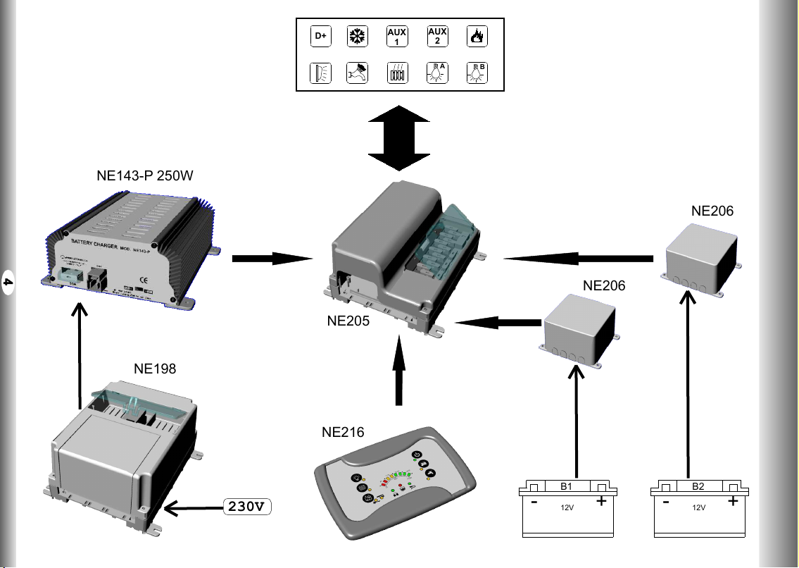
FUNZIONAMENTO:
Utenze azionate dal pannello comandi:
Con il pannello spento tutte le uscite sono disabilitate attraverso gli interruttori generali security box B1
e B2.
Con il pannello acceso si attiva l'interruttore generale security box B2.
L'interruttore security box B2 non si attiva se la tensione della batteria servizi è inferiore a 6Volt (questo
anche in presenza della rete 230Volt).
Le uscite: Luci_A e Luci_B, Luce esterna e Pompa sono azionate direttamente dai relativi tasti del
pannello comandi.
Utenze azionate dal D+:
Le uscite JP4, JP5 e JP6 sono attive solamente con il motore acceso. Con motore acceso e con
tensione della batteria del veicolo maggiore di 13,3Volt per più di 15 sec. si attiva l'uscita frigo ed i due
relè generali security box B1 e B2 (in questo modo avviene l'accoppiamento delle batterie). L'uscita
frigo e l'accoppiamento si disattivano immediatamente se la tensione scende sotto i 12Volt o
spegnendo il motore.
L'accoppiamento provvede alla ricarica della batteria servizi tramite l'alternatore. Il relè frigo permette
di alimentare a 12V il frigo trivalente sempre quando il motore è in moto.
La luce esterna si spegne automaticamente con il motore in moto.
DERIVATORE NE205_11DERIVATORE NE205_11 IIII
F1 20A
AUX
1
F2 20A
F3 10A
F4 10A
F5 5A
F6 3A
F7 20A
F8 20A
F9 30A
F10 3A
MOD. NE205
V. A
DISTRIBUTION 12V
12V DISTRIBUTION
B
A
AUX
2
D+
www.nordelettronica.it
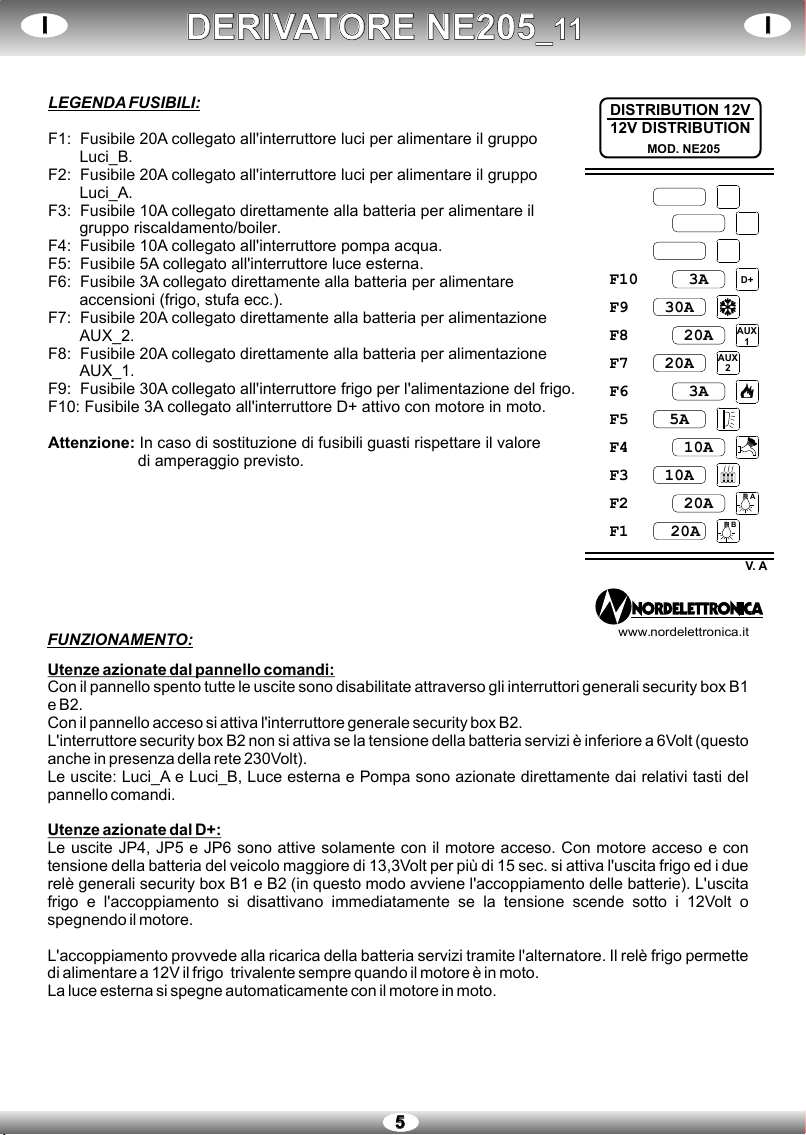
LEGENDA FUSIBILI:
F1: Fusibile 20A collegato all'interruttore luci per alimentare il gruppo
Luci_B.
F2: Fusibile 20A collegato all'interruttore luci per alimentare il gruppo
Luci_A.
F3: Fusibile 10A collegato direttamente alla batteria per alimentare il
gruppo riscaldamento/boiler.
F4: Fusibile 10A collegato all'interruttore pompa acqua.
F5: Fusibile 5A collegato all'interruttore luce esterna.
F6: Fusibile 3A collegato direttamente alla batteria per alimentare
accensioni (frigo, stufa ecc.).
F7: Fusibile 20A collegato direttamente alla batteria per alimentazione
AUX_2.
F8: Fusibile 20A collegato direttamente alla batteria per alimentazione
AUX_1.
F9: Fusibile 30A collegato all'interruttore frigo per l'alimentazione del frigo.
F10: Fusibile 3A collegato all'interruttore D+ attivo con motore in moto.
Attenzione: In caso di sostituzione di fusibili guasti rispettare il valore
di amperaggio previsto.
PANNELLO COMANDI NE216_11PANNELLO COMANDI NE216_11 IIII
66
1
9
8
7
2
3
654
10
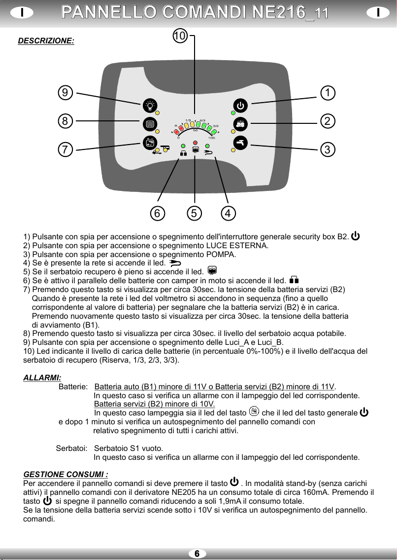
DESCRIZIONE:
1) Pulsante con spia per accensione o spegnimento dell'interruttore generale security box B2.
2) Pulsante con spia per accensione o spegnimento LUCE ESTERNA.
3) Pulsante con spia per accensione o spegnimento POMPA.
4) Se è presente la rete si accende il led.
5) Se il serbatoio recupero è pieno si accende il led.
6) Se è attivo il parallelo delle batterie con camper in moto si accende il led.
7) Premendo questo tasto si visualizza per circa 30sec. la tensione della batteria servizi (B2)
Quando è presente la rete i led del voltmetro si accendono in sequenza (fino a quello
corrispondente al valore di batteria) per segnalare che la batteria servizi (B2) è in carica.
Premendo nuovamente questo tasto si visualizza per circa 30sec. la tensione della batteria
di avviamento (B1).
8) Premendo questo tasto si visualizza per circa 30sec. il livello del serbatoio acqua potabile.
9) Pulsante con spia per accensione o spegnimento delle Luci_A e Luci_B.
10) Led indicante il livello di carica delle batterie (in percentuale 0%-100%) e il livello dell'acqua del
serbatoio di recupero (Riserva, 1/3, 2/3, 3/3).
ALLARMI:
Batterie: Batteria auto (B1) minore di 11V o Batteria servizi (B2) minore di 11V.
In questo caso si verifica un allarme con il lampeggio del led corrispondente.
Batteria servizi (B2) minore di 10V.
In questo caso lampeggia sia il led del tasto che il led del tasto generale
e dopo 1 minuto si verifica un autospegnimento del pannello comandi con
relativo spegnimento di tutti i carichi attivi.
Serbatoi: Serbatoio S1 vuoto.
In questo caso si verifica un allarme con il lampeggio del led corrispondente.
GESTIONE CONSUMI :
Per accendere il pannello comandi si deve premere il tasto . In modalità stand-by (senza carichi
attivi) il pannello comandi con il derivatore NE205 ha un consumo totale di circa 160mA. Premendo il
tasto si spegne il pannello comandi riducendo a soli 1,9mA il consumo totale.
Se la tensione della batteria servizi scende sotto i 10V si verifica un autospegnimento del pannello.
comandi.

77
CARICA BATTERIE NE143-PCARICA BATTERIE NE143-P IIII
DESCRIZIONE:
L' NE143-P è un Carica Batterie per accumulatori al piombo e al gel. Le batterie devono avere una tensione
nominale di 12V ed una capacità non inferiore a 50Ah.
FUNZIONAMENTO:
Il caricabatterie impiega una combinazione di carica a Corrente Costante CCe Tensione
Costante TC. Ciò permette di ridurre in maniera significativa il tempo di carica e di non
danneggiare in modo permanente le batterie. Il caricabatterie inizia a caricare a CC finché
la batteria non raggiunge un valore di tensione pari a VOC dopodichè commuta
nel funzionamento TC. In questa fase il dispositivo fornisce una tensione costante
pari a VOC/VF (14,4/13,8 GEL-14,7/13,8Pb), la corrente di carica si abbassa gradualmente e la batteria può
essere lasciata permanentemente collegata al carica batterie senza danneggiamento.
PROFILI DI CARICA:
Utilizzare l'interruttore posizionato sulla parte frontale del pannello per selezionare il profilo di carica a
seconda del tipo di batteria da ricaricare.
ATTENZIONE :
- Tenere l'apparecchio in luogo asciutto e - Se il cavo di alimentazione o i morsetti di
sufficientemente aerato. connessione alla batteria sono danneggiati questi
- Non fare manutenzioni senza aver staccato devono essere sostituiti con articoli analoghi
l'alimentazione 230V. disponibili presso il costruttore o presso l'assistenza
- Non ostruire le prese d'aria poste sul coperchio. tecnica.
- Evitare di ricaricare batterie non ricaricabili. - Prima di collegare l'alimentazione del carica
- Scollegare l'alimentazione prima di collegare o batterie ad un gruppo elettrogeno accertarsi che
scollegare la connessione alla batteria. l'uscita 230V di quest'ultimo sia stabilizzata.
- Le batterie al piombo acido producono internamente Quando il LED rosso interno è acceso, è necessario
durante la carica gas esplosivi: evitare la formazione di togliere l'alimentazione per azzerare la protezione.
fiamme o scintille e posizionare le batterie in uno spazio
ben ventilato.
PROTEZIONI:
Il carica batterie ha le seguenti protezioni:
-Protezione da inversioni di polarità.
-Protezione da sovraccarico.
-Protezione da corto-circuito.
-Protezione da sovratensione.
Prima di effettuare la carica leggere attentamente il foglio di istruzioni.
Soltanto per utilizzo interno/Non esporre alla pioggia.
CARATTERISTICHE TECNICHE:
Ingresso: 230V ±20% 50/60Hz 1,9A
Corrente massima di uscita (I ): 17A cont.
B
Potenza massima: 250W
Voc Vf
IB
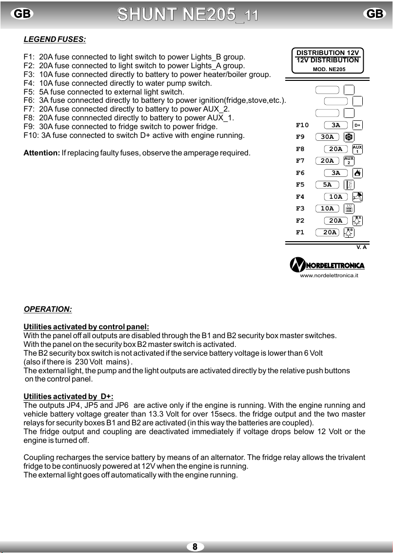
LEGEND FUSES:
F1: 20A fuse connected to light switch to power Lights_B group.
F2: 20A fuse connected to light switch to power Lights_A group.
F3: 10A fuse connected directly to battery to power heater/boiler group.
F4: 10A fuse connected directly to water pump switch.
F5: 5A fuse connected to external light switch.
F6: 3A fuse connected directly to battery to power ignition(fridge,stove,etc.).
F7: 20A fuse connected directly to battery to power AUX_2.
F8: 20A fuse connnected directly to battery to power AUX_1.
F9: 30A fuse connected to fridge switch to power fridge.
F10: 3A fuse connected to switch D+ active with engine running.
Attention: If replacing faulty fuses, observe the amperage required.
OPERATION:
Utilities activated by control panel:
With the panel off all outputs are disabled through the B1 and B2 security box master switches.
With the panel on the security box B2 master switch is activated.
The B2 security box switch is not activated if the service battery voltage is lower than 6 Volt
(also if there is 230 Volt mains) .
The external light, the pump and the light outputs are activated directly by the relative push buttons
on the control panel.
Utilities activated by D+:
The outputs JP4, JP5 and JP6 are active only if the engine is running. With the engine running and
vehicle battery voltage greater than 13.3 Volt for over 15secs. the fridge output and the two master
relays for security boxes B1 and B2 are activated (in this way the batteries are coupled).
The fridge output and coupling are deactivated immediately if voltage drops below 12 Volt or the
engine is turned off.
Coupling recharges the service battery by means of an alternator. The fridge relay allows the trivalent
fridge to be continuosly powered at 12V when the engine is running.
The external light goes off automatically with the engine running.
SHUNT NE205_11SHUNT NE205_11 GBGBGBGB
88
F1 20A
AUX
1
F2 20A
F3 10A
F4 10A
F5 5A
F6 3A
F7 20A
F8 20A
F9 30A
F10 3A
MOD. NE205
V. A
DISTRIBUTION 12V
12V DISTRIBUTION
B
A
AUX
2
D+
www.nordelettronica.it

CONTROL PANEL NE216_11CONTROL PANEL NE216_11 GBGBGBGB
99
DESCRIPTIONS:
1) Push button with warning light for turning on and off the B2 security box master switch.
2) Push button with warning light for turning on and off the EXTERNAL LIGHT.
3) Push button with warning light for turning PUMP on and off.
4) If there is main power the led goes on.
5) If the recycling tank is full the led goes on.
6) If the parallel battery is active with camper engine running the led goes on.
7) Press this button to view service battery (B2) voltage for approx. 30 secs.
When there is power the voltmeter leds illuminate in sequence (up to that corresponding to the
battery value) to signal that the service battery B2 is charging.
Press again this button to view the start-up battery (B1) voltage for approx. 30 secs.
8) Press this button to view the drinking water tank level for approx. 30 secs.
9) Push button with warning light for turning on and off the INTERNAL LIGHTS.
10) LED indicating the battery level (as a percentage 0%-100%) and the level of water in the recycling
tank (Reserve, 1/3, 2/3, 3/3).
ALARMS:
Batteries: Vehicle battery (B1) less than 11V or service battery (B2) less than 11V.
In this case an alarm goes off and the corresponding led flashes.
Service battery (B2) less than 10V.
In this case both the led for button and the general button led flash
and after 1 minute the control panel turns itself off, together with all live parts.
Tanks: Tank S1 empty.
In this case an alarm goes off and the corresponding led flashes.
CONSUMPTION:
To turn on the control panel press the button .
On stand-by (with no live parts) the control panel with NE205 shunt consumes a total of approx.
160mA. When button is pressed the control panel turns itself off and total consumption is
reduced to just 1.9mA.
If the service battery voltage drops below 10V the control panel automatically turns itself off.
1
9
8
7
2
3
654
10
1010
BATTERY CHARGER NE143-PBATTERY CHARGER NE143-P GBGBGBGB
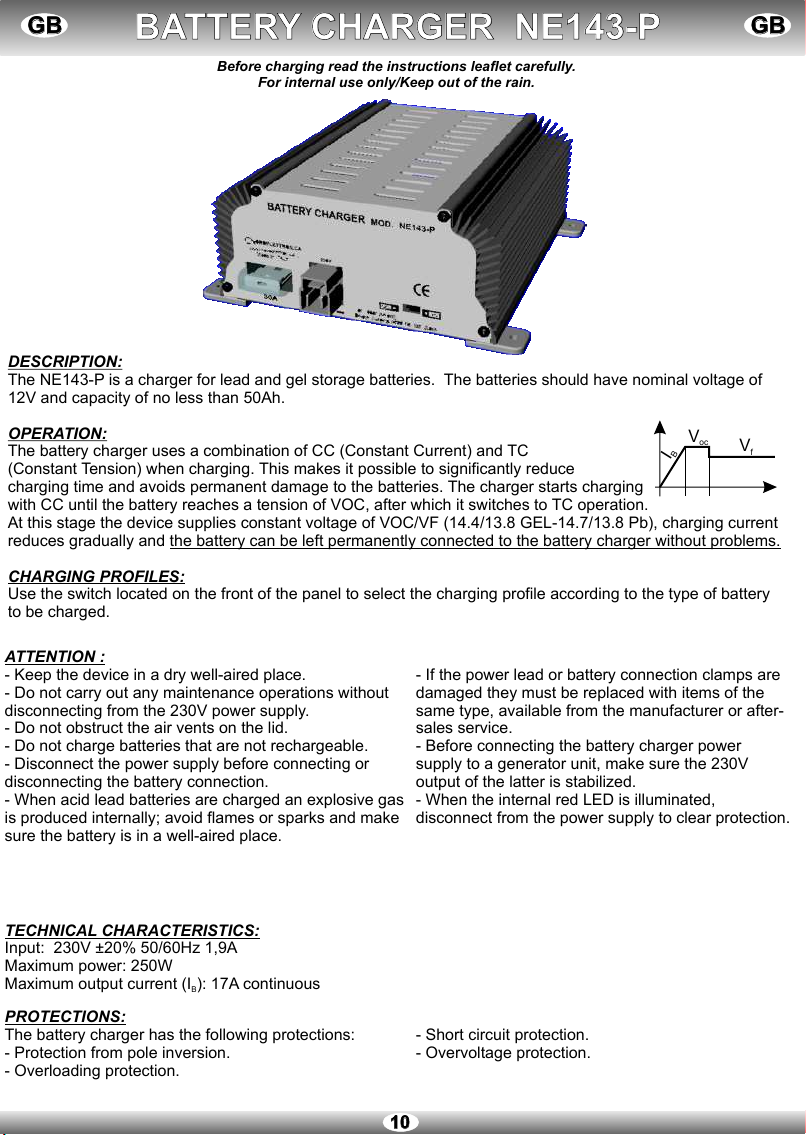
DESCRIPTION:
The NE143-P is a charger for lead and gel storage batteries. The batteries should have nominal voltage of
12V and capacity of no less than 50Ah.
OPERATION:
The battery charger uses a combination of CC (Constant Current) and TC
(Constant Tension) when charging. This makes it possible to significantly reduce
charging time and avoids permanent damage to the batteries. The charger starts charging
with CC until the battery reaches a tension of VOC, after which it switches to TC operation.
At this stage the device supplies constant voltage of VOC/VF (14.4/13.8 GEL-14.7/13.8 Pb), charging current
reduces gradually and the battery can be left permanently connected to the battery charger without problems.
CHARGING PROFILES:
Use the switch located on the front of the panel to select the charging profile according to the type of battery
to be charged.
ATTENTION :
- Keep the device in a dry well-aired place. - If the power lead or battery connection clamps are
- Do not carry out any maintenance operations without damaged they must be replaced with items of the
disconnecting from the 230V power supply. same type, available from the manufacturer or after-
- Do not obstruct the air vents on the lid. sales service.
- Do not charge batteries that are not rechargeable. - Before connecting the battery charger power
- Disconnect the power supply before connecting or supply to a generator unit, make sure the 230V
disconnecting the battery connection. output of the latter is stabilized.
- When acid lead batteries are charged an explosive gas - When the internal red LED is illuminated,
is produced internally; avoid flames or sparks and make disconnect from the power supply to clear protection.
sure the battery is in a well-aired place.
PROTECTIONS:
The battery charger has the following protections:
- Protection from pole inversion.
- Overloading protection.
- Short circuit protection.
- Overvoltage protection.
Before charging read the instructions leaflet carefully.
For internal use only/Keep out of the rain.
TECHNICAL CHARACTERISTICS:
Input: 230V ±20% 50/60Hz 1,9A
Maximum output current (I ): 17A continuous
B
Maximum power: 250W
Voc Vf
IB

1111
FONCTIONNEMENT:
Servitudes actionnées du panneau de commandes :
Quand le panneau est éteint, toutes les sorties sont hors service ainsi que les boites relais B1 et B2.
Quand le panneau est allumé s’active le circuit B2.
L'interrupteur security box B2 n'entre pas en service si la tension de la batterie de service est
inférieure à 6 Volts (et ce même en présence d'un réseau 230Volts).
Les sorties del'interrupteur LUMIÈRES, l'éclairage externe et de la pompe sont activées directement
par les touches correspondantes sur panneau de commande.
Utilisation des commandes par D+:
Les sorties JP4, JP5 et JP6 ne sont en service que si le moteur tourne. Quand le moteur tourne et que
la tension de la batterie du véhicule est supérieure à 13,3 Volts après une temporisation de 15 sec. on
met en service la sortie réfrigérateur et les deux relais généraux security box B1 et B2 (on réalise ainsi
le couplage des batteries). La sortie réfrigérateur et le couplage se désactivera immédiatement si la
tension descend sous 12Volts ou en éteignant le moteur.
C'est le couplage qui assure la recharge de la batterie de service via l'alternateur.
Le relais réfrigérateur permet d'alimenter la puissance 12V du réfrigérateur quand le moteur est en
marche.
L'éclairage externe s'éteint automatiquement quand le moteur est en tourne.
DERIVATEUR NE205_11DERIVATEUR NE205_11 FFFF
F1 20A
AUX
1
F2 20A
F3 10A
F4 10A
F5 5A
F6 3A
F7 20A
F8 20A
F9 30A
F10 3A
MOD. NE205
V. A
DISTRIBUTION 12V
12V DISTRIBUTION
B
A
AUX
2
D+
www.nordelettronica.it
LÉGENDE FUSIBLES :
F1: Fusible 20A raccordé au circuit qui alimente le groupe des Lumières
_B.
F2: Fusible 20A raccordé au circuit qui alimente le groupe des Lumières
_A.
F3: Fusible 10A raccordé directement à la batterie pour alimenter le
groupe chauffage/chauffe-eau.
F4: Fusible 10A raccordé à l'interrupteur pompe à eau.
F5: Fusible 5A raccordé à l'interrupteur de l'éclairage externe.
F6: Fusible 3A raccordé directement à la batterie pour alimenter les
allumages (réfrigérateur, plaque de cuisson, etc.).
F7: Fusible 20A raccordé directement à la batterie pour l'alimentation du
AUX_2.
F8: Fusible 20A raccordé directement à la batterie pour l'alimentation du
AUX_1.
F9: Fusible 30A raccordé à l'interrupteur réfrigérateur pour l'alimentation
du réfrigérateur.
F10: Fusible 3A raccordé à l'interrupteur D+ en service et le moteur en
marche.
Attention : En cas de remplacement de fusibles défaillants, respecter le
calibre conseillé.

PANNEAU DE CONTROLE NE216_11PANNEAU DE CONTROLE NE216_11 FFFF
1212
1) Bouton avec voyant d'allumage ou d'extinction du disjoncteur security box B2.
2) Bouton avec voyant d'allumage ou d'extinction de l'ÉCLAIRAGE EXTERNE.
3) Bouton avec voyant d'allumage ou d'extinction de la POMPE.
4) La led s'allume en présence du réseau.
5) La led s'allume quand le réservoir de recyclage est plein.
6) La led s'allume si le batteries sont couplées avec le camping-car en marche.
7) Appuyer sur cette touche pour visualiser pendant 30 sec. environ la tension de la batterie de
services (B2). Quand le réseau est présent, les leds du voltmètre s'allument en séquence (jusqu'à
celui correspondant à la valeur de la batterie) ils indiquent que la batterie de services B2 est en
train d'être chargée. Appuyer de nouveau sur cette touche pour visualiser pendant 30 sec. Environ
la tension de la batterie de démarrage (B1).
8) Appuyer sur cette touche pour visualiser pendant 30 sec environ le niveau du réservoir d'eau
Potable.
9) Bouton avec voyant d'allumage ou d'extinction de l' ÉCLAIRAGE INTERNE.
10) Leds indiquant l’état de charge des batteries (en pourcentage 0%-100%) et du niveau de l’eau
Propre (Reserve, 1/3, 2/3, 3/3).
ALERTES:
Batterie: Batterie auto (B1) inférieure à 11V ou Batterie de services (B2) inférieure à 11V.
Dans ce cas, une alerte se déclenchera et vous verrez clignoter la led
correspondante.
Batterie de services (B2) inférieure à 10V.
Dans ce cas, la led de la touche et la led de la touche générale Clignoteront .
Une minute plus tard le tableau de commande ainsi que toutes
les charges actives s'éteindront.
Réservoirs: Réservoir S1 vide.
Dans ce cas il y aura une alerte et la led correspondante s'allumera.
GÉRER LES CONSOMMATIONS :
Pour allumer le panneau de commande il faut enfoncer la touche .
En stand-by (sans charges actives) le panneau de commande avec le dérivateur NE205 engendrent
une consommation totale de 160mA environ. Appuyer sur la touche pour éteindre le tableau des
commandes et descendre ainsi à 1,9mA seulement la consommation totale. Si la tension de la
batterie de service descend sous les 10V, le panneau de commande s'éteindra de lui-même.
DESCRIPTIONS:
1
9
8
7
2
3
654
10
1313
CHARGEUR DE BATTERIES NE143-PCHARGEUR DE BATTERIES NE143-P FFFF
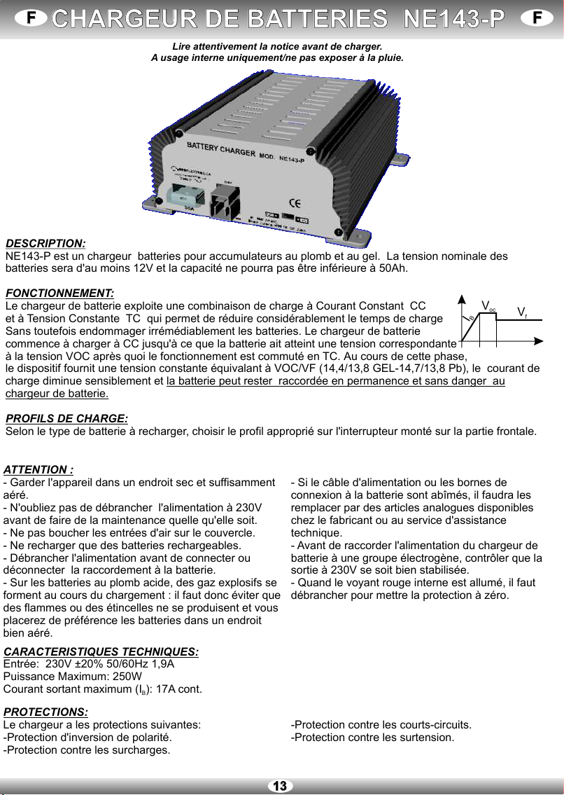
DESCRIPTION:
NE143-P est un chargeur batteries pour accumulateurs au plomb et au gel. La tension nominale des
batteries sera d'au moins 12V et la capacité ne pourra pas être inférieure à 50Ah.
FONCTIONNEMENT:
Le chargeur de batterie exploite une combinaison de charge à Courant Constant CC
et à Tension Constante TC qui permet de réduire considérablement le temps de charge
Sans toutefois endommager irrémédiablement les batteries. Le chargeur de batterie
commence à charger à CC jusqu'à ce que la batterie ait atteint une tension correspondante
à la tension VOC après quoi le fonctionnement est commuté en TC. Au cours de cette phase,
le dispositif fournit une tension constante équivalant à VOC/VF (14,4/13,8 GEL-14,7/13,8 Pb), le courant de
charge diminue sensiblement et la batterie peut rester raccordée en permanence et sans danger au
chargeur de batterie.
PROFILS DE CHARGE:
Selon le type de batterie à recharger, choisir le profil approprié sur l'interrupteur monté sur la partie frontale.
ATTENTION :
- Garder l'appareil dans un endroit sec et suffisamment - Si le câble d'alimentation ou les bornes de
aéré. connexion à la batterie sont abîmés, il faudra les
- N'oubliez pas de débrancher l'alimentation à 230V remplacer par des articles analogues disponibles
avant de faire de la maintenance quelle qu'elle soit. chez le fabricant ou au service d'assistance
- Ne pas boucher les entrées d'air sur le couvercle. technique.
- Ne recharger que des batteries rechargeables. - Avant de raccorder l'alimentation du chargeur de
- Débrancher l'alimentation avant de connecter ou batterie à une groupe électrogène, contrôler que la
déconnecter la raccordement à la batterie. sortie à 230V se soit bien stabilisée.
- Sur les batteries au plomb acide, des gaz explosifs se - Quand le voyant rouge interne est allumé, il faut
forment au cours du chargement : il faut donc éviter que débrancher pour mettre la protection à zéro.
des flammes ou des étincelles ne se produisent et vous
placerez de préférence les batteries dans un endroit
bien aéré.
PROTECTIONS:
Le chargeur a les protections suivantes:
- . - .
- .
-Protection contre les courts-circuits.
Protection d'inversion de polarité Protection contre les surtension
Protection contre les surcharges
Lire attentivement la notice avant de charger.
A usage interne uniquement/ne pas exposer à la pluie.
CARACTERISTIQUES TECHNIQUES:
Entrée: 230V ±20% 50/60Hz 1,9A
Courant sortant maximum (I ): 17A cont.
B
Puissance Maximum: 250W
Voc Vf
IB

1414
BETRIEBSWEISE:
Über das Bedienungspaneel gesteuerte Verbraucher:
Bei ausgeschaltetem Bedienungspaneel werden alle Ausgänge über die Hauptschalter Security Box
B1 und B2 deaktiviert. Der Schalter Security Box B2 wird nicht aktiviert, wenn die Spannung der
Servicebatterie unter 6Volt liegt (auch bei Netzspannung von 230Volt).
Die Ausgänge der Außenbeleuchtung, der Lichtschalter (BELEUCHTUNG_A und
BELEUCHTUNG_B) und der Pumpe werden direkt über die entsprechenden Tasten auf dem
Bedienungspaneel aktiviert.
Von D+ aktivierte Verbraucher:
Die Ausgänge JP4, JP5 und JP6 sind nur bei laufendem Motor aktiviert. Bei laufendem Motor und
Spannung der Fahrzeugbatterie mehr als 15 Sekunden lang über 13,3Volt wird der
Kühlschrankausgang und die zwei Hauptrelais Security Box B1 und B2 aktiviert (auf diese Weise
erfolgt die Kopplung der Batterien). Der Kühlschrankausgang und die Kopplung werden sofort
deaktiviert, wenn die Spannung unter 12V sinkt oder der Motor abgestellt wird.
Die Kopplung sieht ein Wiederaufladen der Batterie über den Drehstromgenerator vor. Das
Kühlschrankrelais ermöglicht die Stromversorgung mit 12V bei laufendem Motor.
Die Außenbeleuchtung schaltet bei laufendem Motor automatisch aus.
ABZWEIGDOSE NE205_11ABZWEIGDOSE NE205_11 DDDD
F1 20A
AUX
1
F2 20A
F3 10A
F4 10A
F5 5A
F6 3A
F7 20A
F8 20A
F9 30A
F10 3A
MOD. NE205
V. A
DISTRIBUTION 12V
12V DISTRIBUTION
B
A
AUX
2
D+
www.nordelettronica.it
ZEICHENERKLÄRUNG DER SICHERUNGEN :
F1: Sicherung 20A angeschlossen an den Lichtschalter zur Versorgung
der Lichtgruppe B.
F2: Sicherung 20A angeschlossen an den Lichtschalter zur Versorgung
der Lichtgruppe A.
F3: Sicherung 10A direkt angeschlossen an die Batterie zur Versorgung
von Heizung/Boiler.
F4: Sicherung 10A angeschlossen an den Schalter der Wasserpumpe.
F5: Sicherung 5A angeschlossen an den Schalter der
Außenbeleuchtung.
F6: Sicherung 3A direkt angeschlossen an die Batterie zur Versorgung
von Einschaltungen (Kühlschrank, Ofen, usw…).
F7: Sicherung 20A direkt angeschlossen an die Batterie zur Versorgung
von AUX_2.
F8: Sicherung 20A direkt angeschlossen an die Batterie zur Versorgung
von AUX_1.
F9: Sicherung 30A angeschlossen an den Kühlschrankschalter zur
Versorgung des Kühlschranks.
F10:Sicherung 3A angeschlossen an den Schalter D+ aktiv mit laufendem
Motor.
Achtung: Beim Auswechseln von defekten Sicherungen auf den
vorgesehenen Amperewert achten.

BEDIENPANEL NE216_11BEDIENPANEL NE216_11 DDDD
1515
1) Leuchtdrucktaste zum Einschalten oder Ausschalten des Hauptschalters Security box B2.
2) Leuchtdrucktaste zum Einschalten oder Ausschalten der Außenbeleuchtung.
3) Leuchtdrucktaste zum Einschalten und Ausschalten der Pumpe.
4) Beim Anschluss an den Netzstrom schaltet das Led ein.
5) Wenn der Wassertank voll ist, schaltet das Led ein.
6) Sind beide Batterien gleichzeitig bei fahrendem Camper aktiviert, schaltet das Led ein
7) Beim drücken dieser Taste wird die Spannung der Servicebatterie (B2) ca. 30 Sekunden lang
angezeigt. Bei Anschluss an den Netzstrom schalten die Led des Voltmeters hintereinander ein (bis
zum dem Batteriewert entsprechenden), um anzuzeigen, dass die Servicebatterie B2 aufgeladen
wird. Beim Drücken wieder dieser Taste wird die Spannung der Startbatterie (B1) ca. 30 Sekunden
lang angezeigt.
8) Beim Drücken dieser Taste wird der Stand im Trinkwassertank ca. 30 Sekunden lang angezeigt.
9) Leuchtdrucktaste zum Einschalten und Ausschalten der Innenbeleuchtung.
10) Led zur Anzeige des Ladestands der Batterien (in Prozenten 0%-100%) und des Wasserstands im
Tank (Reserve, 1/3, 2/3, 3/3).
ALARME:
Batterie: Autobatterie (B1) unter 11V oder Servicebatterie (B2) unter 11V.
In diesem Fall erscheint eine Alarmanzeige durch Blinken des entsprechenden Led.
Servicebatterie (B2) unter 10V.
In diesem Fall leuchtet sowohl das Led der Taste als auch das Led der
Haupttaste auf und nach zirka 1 Minute schaltet das Bedienungspaneel
Mit allen aktiven Ladungen automatisch aus.
Tanks: Tank S1 leer.
In diesem Fall erscheint eine Alarmanzeige durch Blinken des entsprechenden Led.
VERBRAUCH:
Zum Einschalten des Bedienungspaneels die Taste drücken.
In der Modalität Stand-by (ohne angeschlossene Lasten) hat das Bedienungspaneel mit dem
Nebenschluss NE205 einen Gesamtverbrauch von zirka 160mA. Beim Drücken der Taste schaltet
das Bedienungspaneel aus und der Gesamtverbrauch wird auf 1,9mA reduziert.
Sinkt die Spannung der Servicebatterie unter 10V, schaltet das Bedienungspaneel automatisch aus.
BESCHREIBUNG:
1
9
8
7
2
3
654
10

1616
DDDD
BESCHREIBUNG:
NE143-P ist ein Batterie-Ladegerät für Bleiakkumulatoren und Gelakkumulatoren. Die Batterien müssen eine
Nennspannung von 12V und eine Kapazität von mindestens 50Ah aufweisen.
BETRIEBSWEISE:
Das Batterieladegerät arbeitet mit einer Ladekombination von Gleichstrom und konstanter
Spannung TC. Dadurch wird die Ladezeit stark reduziert und die Batterien werden nicht
permanent beschädigt. Das Ladegerät beginnt mit Gleichstrom zu laden bis die Batterie
einen Spannungswert gleich VOC erreicht hat; dann schaltet es auf TC- Betrieb um.
In dieser Phase liefert das Ladegerät konstante Spannung VOC/VF (14,4/13,8 GEL-14,7/13,8Pb), der
Ladestrom senkt sich schrittweise und die Batterie kann permanent angeschlossen bleiben, ohne beschädigt
zu werden.
LADEPROFILE:
Mit Hilfe des Schalters auf der Vorderseite der Bedienungstafel je nach Art der zu ladenden Batterie das
Ladeprofil einstellen.
ACHTUNG :
- Das Ladegerät an einem trockenen und ausreichend - Sind das Speisekabel oder die Anschlussklemmen
belüfteten Ort aufbewahren. an die Batterie beschädigt, müssen sie durch
- Bei Wartungsarbeiten vorher die 230V Stromzufuhr gleichwertige Artikel ersetzt werden, die beim
ausstecken. Hersteller oder dem Kundendienst erhältlich sind.
- Die Luftlöcher auf dem Deckel nicht verstopfen. - Vor dem Anschließen des Ladegerätes an ein
- Keine nicht aufladbaren Batterien laden. Elektroaggregat sicherstellen, dass der 230V
- Die Stromzufuhr vor dem Ein/oder Ausstecken des Ausgang des Letzteren stabilisiert ist.
Anschlusses an die Batterie unterbrechen. - Schaltet das interne LED ein, muss die Zufuhr
- Saure Bleibatterien erzeugen während des Ladens im unterbrochen werden, um den Schutz auf Null zu
Inneren explosives Gas: darauf achten, dass sich keine Stellen.
Flammen oder Funken bilden und die Batterie an einem
gut belüfteten Ort positionieren.
SCHUTZVORRICHTUNGEN:
Das Ladegerät ist mit folgenden Schutzvorrichtungen
ausgestattet: -Kurzschlussschutz.
-Schutz vor Polaritätsumkehr. -Überspannungsschutz.
-Überlastschutz.
Vor dem Laden die Bedienungsanleitung sorgfältig durchlesen.
Nur für den Gebrauch in geschlossenen Räumen/Nicht dem Regen aussetzen.
TECHNISCHE EIGENSCHAFTEN:
Eingang: 230V ±20% 50/60Hz 1,9A
Max. Ausgangsstrom (I ): 17A gleichstrom
B
Höchstleistung: 250W
Voc Vf
IB
BATTERIE-LADEGERÄT NE143-PBATTERIE-LADEGERÄT NE143-P

FUNCIONAMIENTO:
Utilizaciones accionadas desde el tablero de mandos :
Con el tablero apagado todas las salidas son deshabilitadas mediante los interruptores generales
security box B1 y B2. Con el tablero encendido se activa el interruptor general security box B2.
El interruptor security box B2 no se activa si la tensión de la batería servicios es inferior a 6Voltios (esto
también en presencia de la red de 230Voltios).
Las salidas luz exterior, el interruptor LUCES (LUCES_A y LUCES_B) y bomba son accionadas
directamente con los botones correspondientes del tablero de mandos.
Utilizaciones accionadas por el D+:
Las salidas JP4, JP5 y JP6 son activas solamente con el motor encendido. Con el motor encendido y
con tensión de la batería del vehículo mayor de 13,3Voltios durante más de 15 seg. se activa la salida
frigorífico y los dos relés generales security box B1 y B2 (de este modo se produce el acoplamiento de
las baterías). La salida frigorífico y el acoplamiento se desactivan inmediatamente si la tensión
desciende por debajo de los 12Voltios o apagando el motor.
El acoplamiento realiza la recarga de la batería de los servicios mediante el alternador. El relé
frigorífico permite alimentar a 12V el frigorífico trivalente siempre que el motor esté arrancado.
La luz exterior se apaga automáticamente con el motor arrancado.
L'éclairage externe s'éteint automatiquement quand le moteur est en tourne.
F1 20A
AUX
1
F2 20A
F3 10A
F4 10A
F5 5A
F6 3A
F7 20A
F8 20A
F9 30A
F10 3A
MOD. NE205
V. A
DISTRIBUTION 12V
12V DISTRIBUTION
B
A
AUX
2
D+
www.nordelettronica.it
LEYENDA FUSIBLES :
F1: Fusible 20A conectado al interruptor luces para alimentar el grupo
Luces_B.
F2: Fusible 20A conectado al interruptor luces para alimentar el grupo
Luces_A.
F3: Fusible 10A conectado directamente a la batería para alimentar el
grupo calefacción/calentador.
F4: Fusible 10A conectado al interruptor bomba agua.
F5: Fusible 5A conectado al interruptor luz exterior.
F6: Fusible 3A conectado directamente a la batería para alimentar
encendidos (frigorífico, estufa etc.).
F7: Fusible 20A conectado directamente a la batería para alimentación
AUX_2.
F8: Fusible 20A conectado directamente a la batería para alimentación
AUX_1.
F9: Fusible 30A conectado al interruptor frigorífico para la alimentación
del frigorífico.
F10: Fusible 3A conectado al interruptor D+ activo con motor arrancado.
Atención: En caso de tener que sustituir los fusibles averiados respetar
el valor de amperaje previsto.
1717
DERIVADOR NE205_11DERIVADOR NE205_11 EEEE

1) Botón con indicador luminoso para encendido o apagado del interruptor general security box B2.
2) Botón con indicador luminoso para encendido o apagado de la Luz Exterior.
3) Botón con indicador luminoso para encendido o apagado de la Bomba.
4) Si está presente la tensión de red se enciende el led.
5) Si el depósito de recuperación está lleno se enciende el led.
6) Si está activo el paralelo de las baterías con la autocaravana arrancada se enciende el led
7) Pulsando este botón se visualiza durante 30 seg. aproximadamente la tensión de la batería de los
servicios (B2). Cuando está presente la tensión de red los led del voltímetro se encienden en
secuencia (hasta el que corresponde al valor de batería) para señalar que la batería de los
servicios B2 está cargando. Pulsando nuovmente este botón se visualiza durante 30 seg.
aproximadamente la tensión de la batería de arranque (B1).
8) Pulsando este botón se visualiza durante 30 seg. aproximadamente el nivel del depósito de agua
potable.
9) Botón con indicador luminoso para encendido o apagado del interruptor general Luces Interiores.
10) Led que indica el nivel de carga de las baterías (con porcentaje 0%-100%) y el nivel del agua en
el depósito de recuperación (Reserva 1/3, 2/3, 3/3).
ALARMAS:
Baterías: Batería auto (B1) menor de 11V o Batería servicios (B2) menor de 11V.
En este caso se verifica una alarma con brillo intermitente del led correspondiente.
Batería servicios (B2) menor de 10V.
En este caso parpadea tanto el led del botón como el led del botón general
y transcurrido 1 minuto se verifica un auto-apagado del tablero de mandos
con correspondiente apagado de todas las cargas activas.
Depósitos: Depósito S1 vacío.
En este caso se produce una alarma con el parpadeo del led correspondiente.
GESTIÓN DE CONSUMOS:
Para encender el tablero de mandos hay que pulsar el botón . En modalidad stand-by (sin cargas
activas) el tablero de mandos con el derivador NE205 tiene un consumo total de 160mA
aproximadamente. Pulsando el botón se apaga el tablero de mandos reduciendo a tan sólo 1,9mA
el consumo total. Si la tensión de la batería de los servicios desciende por debajo de los 10V se
produce un auto-apagado del tablero de mandos.
TABLERO DE MANDOS NE216_11TABLERO DE MANDOS NE216_11 EEEE
DESCRIPCIÓN:
1818
1
9
8
7
2
3
654
10

1919
EEEE
DESCRIPCIÓN:
El NE143-P es un cargabaterías para acumuladores de plomo y de gel. Las baterías tienen que tener una
tensión nominal de 12V y una capacidad no inferior a los 50Ah.
FUNCIONAMIENTO:
El cargabaterías utiliza una combinación de carga con Corriente Constante CC y Tensión
Constante TC. Esto permite reducir de manera significativa el tiempo de carga y no
dañar de forma permanente las baterías. El cargabaterías comienza a cargar a CC hasta
que la batería no alcanza un valor de tensión igual a VOC, luego conmuta en el funcionamiento TC. En esta
fase el dispositivo suministra una tensión constante igual a VOC/VF (14,4/13,8 GEL-14,7/13,8Pb), la corriente
de carga desciende gradualmente y la batería puede dejarse permanentemente conectada al cargabaterías
sin que se estropee.
PERFILES DE CARGA:
Utilice el interruptor colocado en la parte frontal del panel para seleccionar el perfil de carga según el tipo de
batería a recargar.
ATENCIÓN:
- Guarde el aparato en un lugar seco y suficientemente - Si el cable de alimentación o los terminales de
ventilado. conexión a la batería están dañados hay que
- No intervenga con operaciones de mantenimiento sin sustituirlos con artículos análogos que podrán ser
haber desconectado antes la alimentación de 230V. suministrados por el constructor o por la asistencia
- No obstruya las tomas de aire colocadas en la tapa. técnica.
- Evite recargar baterías no recargables. - Antes de conectar la alimentación del
- Desconecte la alimentación antes de conectar o cargabaterías a un grupo electrógeno comprobar
desconectar la conexión a la batería. que la salida de 230V de éste último se haya
- Las baterías de plomo ácido producen internamente estabilizado.
durante la carga gases explosivos: evite que se formen - Cuando el LED rojo interno está encendido, es
llamas o chispas y ponga las baterías en un espacio necesario quitar la alimentación para poner a cero la
bien ventilado. protección.
PROTECCIONES:
El cargabaterías tiene las siguientes protecciones:
- Protección contra inversiones de polaridad.
- Protección contra sobrecarga.
- Protección contra cortocircuito.
- Protección contra sobretensión.
Antes de efectuar la carga leer atentamente la página de instrucciones.
Sólo para utilización en interior/ No exponer a la lluvia.
CARACTERÍSTICAS TÉCNICAS:
Entrada: 230V ±20% 50/60Hz 1,9A
Corriente máxima de salida (I ): 17A cont.
B
Potencia máxima: 250W
Voc Vf
IB
CARGA-BATERÍAS NE143-PCARGA-BATERÍAS NE143-P
Powered by TCPDF (www.tcpdf.org)Powered by TCPDF (www.tcpdf.org)
This manual suits for next models
4
Table of contents
Languages:
Other Nordelettronica Control Unit manuals


