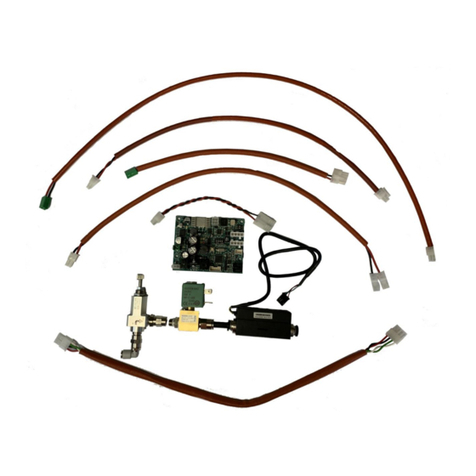
SGS electronic TVC-B30L User manual

TVC-B30L
1
© SGS electronic 2006-2023
TVC-B30L
30A dual speed controller with light control for 1/10 scale and
larger RC tracked vehicles
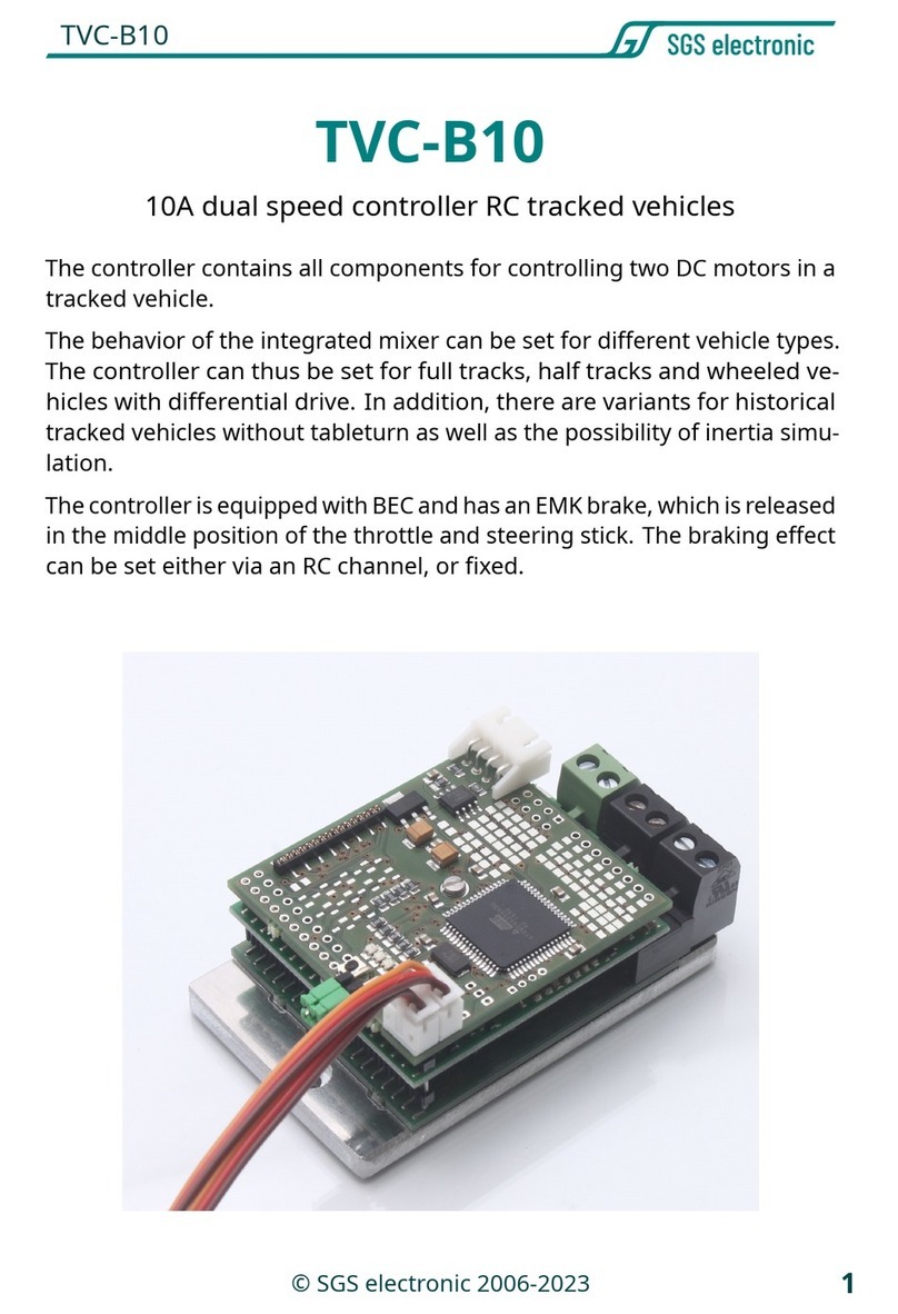
The controller contains all components for controlling two DC motors in a
tracked vehicle.
The behavior of the integrated mixer can be set for different vehicle types.
The controller can thus be set for full tracks, half tracks and wheeled ve-
hicles with differential drive. In addition, there are variants for historical
tracked vehicles without tableturn as well as the possibility of inertia simu-
lation.
The controller is equipped with BEC and has an EMK brake, which is released
in the middle position of the throttle and steering stick. The braking effect
can be set either via an RC channel, or fixed.

TVC-B30L
2© SGS electronic 2006-2023
1 Note
Installation of the module requires intermediate to advanced modeling
skills. Soldering skills are required to connect the wiring. Inexperienced
modelers and persons aged under 16 years old should seek the assistance
of an experienced modeler. Always switch off power when working on
the wiring. Especial take care when connecting more than one receiver
energy source. Prevent the device from getting wet. Check loads before
connecting them to the modul at a current limited, or fuse protected
source.

TVC-B30L
3
© SGS electronic 2006-2023
Contents
1 Note 2
2 Introduction 6
2.1 Technology................................. 6
2.2 Scopeofdelivery............................. 7
3 Functional description 8
3.1 Manualcontrol .............................. 8
3.1.1 Channel 1 - proportional forward/back . . . . . . . . . . 8
3.1.2 channel 2 - proportional left/right . . . . . . . . . . . . . 8
3.1.3 Channel 3 - Light mode control . . . . . . . . . . . . . . . 8
3.1.4 channel 4 - EMF brake . . . . . . . . . . . . . . . . . . . . . 8
3.2 Function of light mode switching . . . . . . . . . . . . . . . . . . 9
3.2.1 Lightmode1........................... 9
3.3 Drive dynamic functions . . . . . . . . . . . . . . . . . . . . . . . . 10
3.3.1 Reversinglights ......................... 10
3.3.2 Aroundlight ........................... 10
3.3.3 Indicator Left + Right . . . . . . . . . . . . . . . . . . . . . . 10
3.3.4 Brakelight ............................ 11
4 Installation 12
5 Connections 13
5.1 Batteryconnection............................ 13
5.2 Connecting the motors . . . . . . . . . . . . . . . . . . . . . . . . . 14
5.3 Connecting the servo cables . . . . . . . . . . . . . . . . . . . . . 14
5.4 BECjumpers................................ 15
5.5 Anschluss der Lichtausgänge . . . . . . . . . . . . . . . . . . . . . 16
5.6 Scalebus operation (optional) . . . . . . . . . . . . . . . . . . . . . 17
6 Commissioning 19
6.1 Startup ................................... 19
6.2 Correct driving direction . . . . . . . . . . . . . . . . . . . . . . . . 19
6.3 EMFbrake ................................. 20
6.3.1 Setting via an RC channel of the controller . . . . . . . . 20

TVC-B30L
4© SGS electronic 2006-2023
6.3.2 Without RC channel with pushbutton . . . . . . . . . . . 20
6.4 Errorstates ................................ 21
6.5 Changing the mixing function . . . . . . . . . . . . . . . . . . . . 22
6.5.1 How to change mixer function . . . . . . . . . . . . . . . . 22
7 Glossary of terms 24
8 Technical data 26
9 Important 27
9.1 Warning .................................. 27
9.2 Environmental protection . . . . . . . . . . . . . . . . . . . . . . . 27
9.3 Address................................... 28
9.4 Contact ................................... 28
9.5 Documentdate.............................. 28
9.6 Documentation.............................. 28
List of Figures
1 mountingholes.............................. 12
2 connectionsoverview.......................... 13
3 Assignment of the connector for power supply . . . . . . . . . 13
4 pinoutservocable............................ 14
5 servocableposition........................... 15
6 do not forward BEC voltage to receiver . . . . . . . . . . . . . . 16
7 forward BEC voltage to receiver . . . . . . . . . . . . . . . . . . . 16
8 Belegung der Lichtausgänge . . . . . . . . . . . . . . . . . . . . . 17
List of Tables
1 Overviewrcinputs............................ 9
2 Lightmode1 ............................... 9
3 Lightmode2 ............................... 10
4 servo cable assignment . . . . . . . . . . . . . . . . . . . . . . . . 15
5 Belegung der Lichtausgänge . . . . . . . . . . . . . . . . . . . . . 16
6 Errorcodes ................................ 21

TVC-B30L
6© SGS electronic 2006-2023
2 Introduction
The controller is designed for an input voltage range from 6.5V to 24V.
This means that the controller works with the 6 cell NC packs commonly
used in the RC car sector, but also with lead batteries up to 24V. Two stan-
dard automotive fuses protect the model and the battery from excessive
currents.
The controller has a built-in BEC circuit to power the receiver from the drive
battery.
Please note that the removable BEC current decreases as the supply voltage
increases.
To disconnect the internal BEC regulator from the receiver supply, a jumper
must be removed.
As a failsafe function, an extensive plausibility check of the transmitter
signals is integrated in the software.
In addition, the controller has a temperature monitoring of the output
stage.
It switches off at 75°C and can be switched on again at 65°C and above.
To do this, the transmitter sticks must be set to the neutral position to
prevent a sudden start after the controller has cooled down.
2.1 Technology
The controller is microprocessor controlled. The processor operates with
16MHz clock frequency.
The output stage is constructed of N-channel MOSFETs, which have an
inrush resistance of only 0.008 Ohm and a continuous current capability of
60A. Three of these transistors each form a power stage branch, enabling
peak currents of up to 180A. To make effective use of the low internal
resistance, the output stage transistors are driven by sophisticated MOSFET
push-pull output stages with integrated charge pump.
Under normal ambient conditions, a continuous current of 30A is achieved.
The controller operates with a PWM frequency of 16kHz.

TVC-B30L
7
© SGS electronic 2006-2023
2.2 Scope of delivery
The controller is supplied with the connectors for the motor connection
and the battery connection.

TVC-B30L
8© SGS electronic 2006-2023
3 Functional description
3.1 Manual control
A radio remote control with at least one proportional channel is required
to control the module. To use all functions, four RC channels are required.
3.1.1 Channel 1 - proportional forward/back
Direction of rotation for the motor. From the throttle channel is also derived
reverse light on/off, brake light).
3.1.2 channel 2 - proportional left/right
The control of the turn signals is derived from this channel. It is usually
connected to the steering channel with a V-cable, parallel to the steering
servo. If the channel is not connected, the turn signals only function as
warning turn signals.
3.1.3 Channel 3 - Light mode control
This channel can be used to switch the all-round light and the hazard
warning lights, as well as two freely assignable outputs. If the channel is
not used, the rotating beacon is permanently active and the hazard lights
are switched off. The two freely assignable outputs are also switched off.
3.1.4 channel 4 - EMF brake
This channel can be used to set the braking effect of the holding brake. If
this channel is not connected, the brake function can be permanently set
on the controller.

TVC-B30L
9
© SGS electronic 2006-2023
Channel connector optional function
1 X50 no gas
2 X51 yes steering
3 X52 yes light control
4 X53 yes brake action
Table 1: Overview rc inputs
3.2 Function of light mode switching
There are two light modes which are controlled independently by RC chan-
nel.
3.2.1 Light mode 1
Light mode 1 controls two outputs for universally usable lamps (auxlight
1 and 2). They can be used, for example, for the low beam, the front
headlights or searchlights.
Light mode 1 is switched on by tapping the control element from the
center position to
front
. The modes are switched on by briefly tapping the
channel (1 � 2 � 3 � 4 � 1, etc.). Long pressing (approx. 2s) always selects
”state 1” (all off).
state 1 2 3 4
auxlight 1 off on off on
auxlight 2 off off on on
Table 2: Light mode 1
Light mode 2 Light mode 2 controls the automatic light functions for the
turn signal and the rotating light. In the different light modes, the lamp
outputs are switched as shown in the table.
By pressing the key for a long time (approx. 2s), ”state 1” is always selected.
After switching on, the model is in light mode ”state 1”.

TVC-B30L
10 © SGS electronic 2006-2023
state 1 2 3 4
Hazard warning lights off on off on
Rotating light 1,2,3,4 off off on (Running lights) on (Running lights)
Table 3: Light mode 2
Note
Typically, one uses a channel with three-position pushbutton on
the transmitter side (A pushbutton with automatic center position). Propor-
tional channels with sliding or rotary potentiometers make the selection
of the light mode more difficult, because the switching should be done by
short actuation with reset to the center position. This is difficult to handle
with sliding or rotary potentiometers.
3.3 Drive dynamic functions
3.3.1 Reversing lights
The reverse light output is turned on as soon as the throttle lever steers
backward. Once the throttle is in neutral or straight, the reverse light is
turned off.
3.3.2 Around light
The rotating light runs at approximately 1.5 revolutions per second. It is
turned on/off by light mode 2.
3.3.3 Indicator Left + Right
From a minimum speed of approx. 10% of the maximum speed, the auto-
matic blinker switches on. When the steering is in the right position, the
right turn signal is flashing, when the steering is in the left position, the left
turn signal output flashes with a frequency of approx. 1Hz. The automatic
turn signal is only active in the driving mode. The hazard warning light can
be switched on or off by the light mode 2.

TVC-B30L
11
© SGS electronic 2006-2023
3.3.4 Brake light
The brake light turns on automatically when the vehicle is decelerating.
The more deceleration, the longer the brake light is on. If acceleration is
resumed, the brake light switches off immediately.

TVC-B30L
12 © SGS electronic 2006-2023
4 Installation
Six M3 screws are provided for mounting the controller. The drill holes are
partially located under the plug-in terminals. If necessary, the controller
can also be screwed onto an aluminum surface to increase the cooling
capacity. In this case, the heat shrink tubing in the contact area should be
removed and thermal paste should be used.
Figure 1: mounting holes

TVC-B30L
13
© SGS electronic 2006-2023
5 Connections
Figure 2: connections overview
5.1 Battery connection
Fahrakku plus (+)
Fahrakku minus (-)
Figure 3: Assignment of the connector for power supply
Power is supplied via the green, plug-in screw terminal. Please pay atten-
tion to the correct polarity of the supply voltage! (see figure 3).
It makes sense to include a switch in the positive supply line to the battery
to switch the model on/off. Never switch the minus in RC model building,
because the minus also the reference potential of the servo signals.
There are two automotive fuses for the motor output stages on the circuit
board. They are pluggable and can be easily replaced if necessary.

TVC-B30L
14 © SGS electronic 2006-2023
If one of the power stage fuses has blown, the BEC still works and the LED
indicates the function. However, the corresponding motor output stage
no longer supplies power. In addition, the BEC circuit also has a fuse. This
is soldered onto the circuit board. If this fuse has blown, the BEC no longer
supplies voltage and the controller no longer shows any function.
5.2 Connecting the motors
Black, plug-in screw terminals are provided for the drive motors. One
motor is connected to each screw terminal. The motors must be radio
interference suppressed, as is usual in model building.
5.3 Connecting the servo cables
The controller is equipped with JR servo cables. The pinout is shown in
figure 4.
Figure 4: pinout servo cable

TVC-B30L
15
© SGS electronic 2006-2023
Figure 5: servo cable position
chan-
nel
Stecker connector Function
1 X50 no throttle
2 X51 yes steering
3 X52 yes light control
4 X53 yes break
Table 4: servo cable assignment
5.4 BEC jumpers
The controller contains a BEC circuit that generates a regulated voltage of
5V from the voltage of the drive battery to supply the receiver and servos.
Since in function models often several controllers with BEC are installed,
but the parallel operation is problematic under certain circumstances, the
connection of the installed BEC to the receiver can be disconnected. Two
green jumpers are used for this purpose.
If the jumpers are inserted vertically, the internal BEC voltage is passed on
to the receiver and from there to the servos.
If the jumpers are inserted horizontally (or are not inserted), the voltage is
not passed on. In this case, another module must supply the receiver with
power.

TVC-B30L
16 © SGS electronic 2006-2023
12345678910
1. Aux
-
2. Aux
-
1.
Run-
dum-
licht
-
2.
Run-
dum-
licht
-
3.
Run-
dum-
licht
-
4.
Run-
dum-
licht
-
Rück-
fahrschein-
werfer
-
Brem-
slicht
-
Blinker
rechts
-
Blinker
links -
1. Aux
+
2. Aux
+
1.
Run-
dum-
licht
+
2.
Run-
dum-
licht
+
3.
Run-
dum-
licht
+
4.
Run-
dum-
licht
+
Rück-
fahrschein-
werfer
+
Brem-
slicht
+
Blinker
rechts
+
Blinker
links +
Table 5: Belegung der Lichtausgänge
Figure 6: do not forward BEC voltage
to receiver
Figure 7: forward BEC voltage to re-
ceiver
5.5 Anschluss der Lichtausgänge
Die Ausgänge schalten die Akkuspannung, daher muss der angeschlossene
Verbraucher für diese Spannung geeignet sein. Wird der Regler z.B. mit
einem 12 Volt Akku betrieben, sollte der Verbraucher ebenfalls für 12V
Nennspannung ausgelegt sein. Bei LEDs sind entsprechende Vorwider-
stände vorzusehen.
Das Schaltvermögen pro Kanal beträgt 300mA.

TVC-B30L
17
© SGS electronic 2006-2023
Figure 8: Belegung der Lichtausgänge
5.6 Scalebus operation (optional)
As an alternative to control via the receiver and the servo cables, the
controller can also be controlled via the scale bus. To do this, the controller
is connected to the other modules with the scale bus cable (white, four-pin
connector).
For example, the FO module TVC-MF-10 can control the controller. The
controller switches to scale bus mode if no servo signal is present at the
two servo cables when it is switched on. Accordingly, the servo cables must
not be plugged into the receiver during scale bus operation.
In scale bus mode, the controlling module specifies the mixing function.
Therefore, a controller for a half-track vehicle can also be operated with an
FO module for a battle tank.
The controller then works as a full track mixer.
Not only the information for controlling the drive motors, but also the
information for the auxiliary drives is sent via the scale bus.
If no jumper is plugged in, the information of the drives is output.

TVC-B30L
18 © SGS electronic 2006-2023
If coding bridges are plugged into servo cables 1 or 2, the motor outputs
are controlled as specified in the description of the FO module.
Example tracked vehicle:
1. No coding jumper plugged
→Controller works as drive controller (drive chains)
2. coding jumper plugged into servo cable 1
→
Controller works as tower control (barrel elevation and tower rota-
tion)
It is of course possible to connect several controllers to the scale bus. It is
also possible for two controllers to output the same information.

TVC-B30L
19
© SGS electronic 2006-2023
6 Commissioning
6.1 Startup
1.
Connectconnect the drive battery on the transmitter the throttle and
control levers to the center position (the corresponding trim as well).
on the receiver. The green LED lights up for approx. 1s.
2.
The green LED on the board flashes until the controller has detected
the center position of the channels. If zero point detection is not
possible, the LED does not light up. The zero point is not determined
again until the receiver is switched on/off.
3. If the green LED is continuously on, the vehicle is ready to drive.
This automatic calibration is done in this way at
every
switch-on. I.e., the
position detected at power-up is stored as the neutral position. This applies
to both steering and speed.
6.2 Correct driving direction
The direction of travel depends on the mechanical arrangement of the
engines in the vehicle. Usually, the motors are mounted so that the motor
shafts are in opposite directions. As a result, the motors must be connected
with different polarity in order to drive in one direction.
Of course the correction of the driving direction can be done directly on
transmitters with the servo reverse setting. If the transmitter does not
have this possibility, you can proceed as follows:
1.
model moves forward when steered backward and vice versa: Change
connections on both motors (reverse polarity).
2.
Model moves left when steered to the right and vice versa: Change con-
nections from both motors, reversing polarity. (connecting line from
motor 1 to motor 2 and vice versa).
3.
The directional control is set to neutral, but the model does not drive
straight ahead: Correct with steering trim

TVC-B30L
20 © SGS electronic 2006-2023
6.3 EMF brake
The controller has an adjustable EMF brake. It is activated by moving the
throttle and steering sticks to the center position.
The braking effect with which the brake is applied is indicated by the yellow
LED. The longer the yellow LED is on, the stronger the braking effect.
• LED Off corresponds to 0% braking effect.
• LED On corresponds to 100% braking action.
The setting can be made in two ways: Via an RC channel of the controller,
so it can be changed via the transmitter at any time, or a button on the
controller. Mode A is automatically selected if the brake channel is inserted
in the receiver when switching on.
6.3.1 Setting via an RC channel of the controller
Here, the braking effect is adjusted directly via the transmitter. As soon
as you press the corresponding slider/rotary knob, you will see that the
pulse/pause ratio changes.
You can thus at any time, for example, lightly brake and further strengthen
the braking effect.
If you have a channel free on your RC system, we recommend this method.
Make sure that they do not stop from full speed with full braking effect, this
puts a lot of strain on the entire drive train. The braking effect is indicated
by the duration of the yellow LED.
6.3.2 Without RC channel with pushbutton
If you want to change the braking effect, you must press the button. The
button is located between the light connector and the jumpers for the BEC.
Use a thin stick made of plastic or wood to press the button. The push
button has a clearly noticeable pressure point.
If you move the throttle in one direction the on phase of the yellow LED
gets longer and longer, in the other direction shorter and shorter until it is
completely off. The stronger the lever deflection, the faster the adjustment.
Table of contents
Other SGS electronic Controllers manuals

