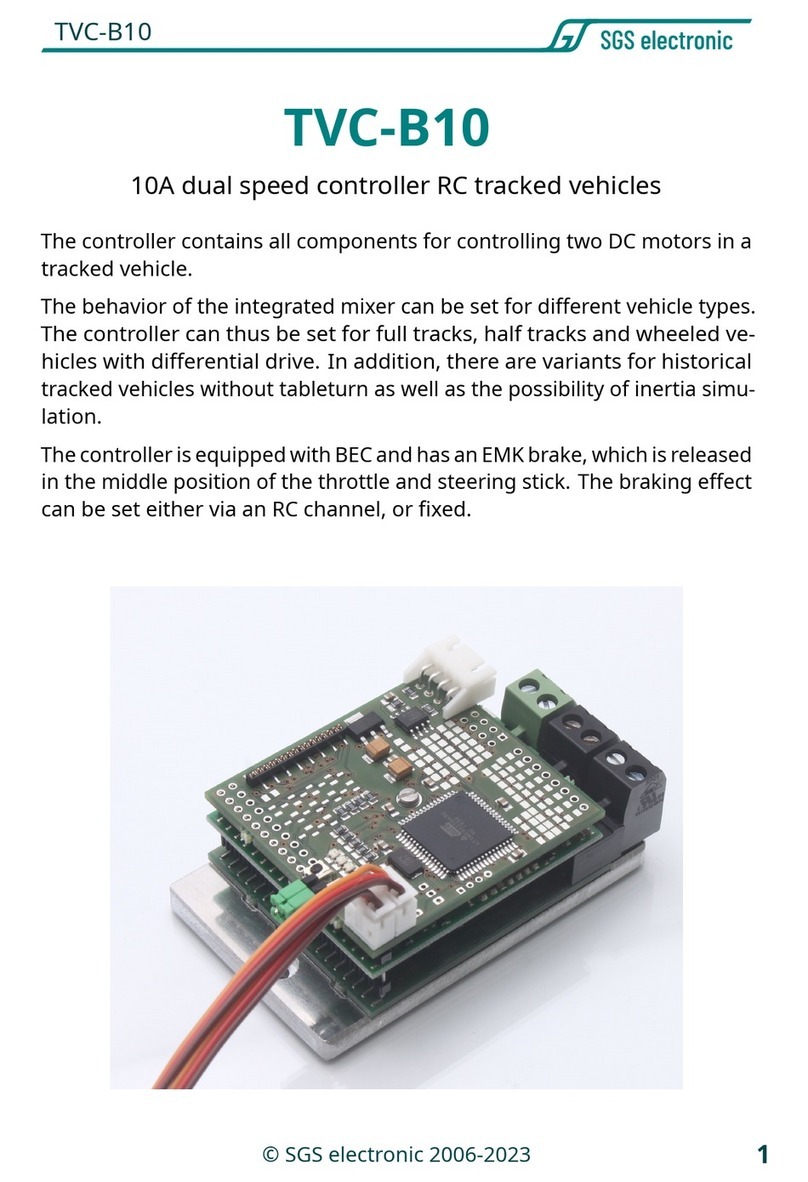
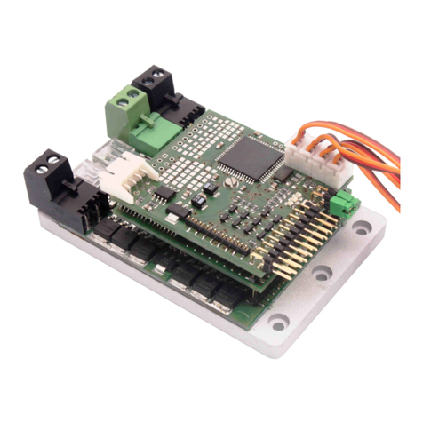
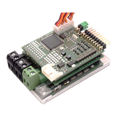
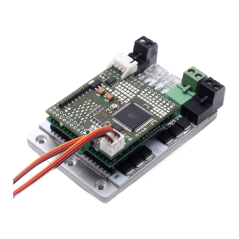
SGS electronic TVC-B100 User manual

TVC-B100
1
© SGS electronic 2006-2023
TVC-B100
100A dual speed controller for RC tracked vehicles
The controller contains all components for controlling two DC motors in a
tracked vehicle.
The behavior of the integrated mixer can be set for different vehicle types.
The controller can thus be set for full tracks, half tracks and wheeled
vehicles with differential drive. In addition, there are variants for historical
tracked vehicles without tableturn as well as the possibility of an inertia
simulation.
The controller has an adjustable EMF standstill brake, which is triggered in
the center position of the throttle and steering stick.

TVC-B100
2© SGS electronic 2006-2023
1 Note
Installation of the module requires intermediate to advanced modeling
skills. Soldering skills are required to connect the wiring. Inexperienced
modelers and persons aged under 16 years old should seek the assistance
of an experienced modeler. Always switch off power when working on
the wiring. Especial take care when connecting more than one receiver
energy source. Prevent the device from getting wet. Check loads before
connecting them to the modul at a current limited, or fuse protected
source.

TVC-B100
3
© SGS electronic 2006-2023
Contents
1 Note 2
2 Introduction 5
2.1 Technology................................. 5
3 Installation 6
3.1 mounting.................................. 6
3.2 Driving battery and motors . . . . . . . . . . . . . . . . . . . . . . 6
3.3 connecting the receiver . . . . . . . . . . . . . . . . . . . . . . . . . 7
3.4 EMFbrake ................................. 8
4 Commissioning 10
4.1 startup ................................... 10
4.2 error acknowledgement . . . . . . . . . . . . . . . . . . . . . . . . 10
4.3 Correct driving direction . . . . . . . . . . . . . . . . . . . . . . . . 11
4.4 Scalebusoperation ........................... 12
4.5 Changing the mixing function . . . . . . . . . . . . . . . . . . . . 13
4.5.1 How to change mixer function . . . . . . . . . . . . . . . . 13
5 Glossary of terms 15
6 Technical data 17
7 Important 18
7.1 Warning .................................. 18
7.2 Environmental protection . . . . . . . . . . . . . . . . . . . . . . . 18
7.3 Address................................... 19
7.4 Contact ................................... 19
7.5 Documentdate.............................. 19
7.6 Documentation.............................. 19
List of Figures
1 Connectionsoverview.......................... 6

TVC-B100
5
© SGS electronic 2006-2023
2 Introduction
The controller is designed for an input voltage range from 12V to 36V. Two
standard automotive fuses (strip fuse) protect the model and the battery
from excessive currents.
In addition, the controller has electronic overload protection (
2t
monitor-
ing) and electronic temperature monitoring of the power output stage.
2.1 Technology
The controller is microprocessor controlled. The processor works with
16MHz clock frequency. The software is coded in C and assembler.
As a failsafe function, an extensive plausibility check of the transmitter
signals is integrated in the software.
The power amplifier is built with N-channel MOSFETs, which have an inrush
resistance of only 0.001 Ohm and a current capability of 180A. To make
effective use of the low internal resistance, the output stage transistors are
driven by sophisticated push-pull MOSFET output stages with integrated
charge pump.
Under normal ambient conditions, a maximum continuous current of 100A
is achieved. The controller operates with a PWM frequency of 16kHz.
. To prevent ground loops and resulting interference, the servo inputs
are galvanically isolated. Accordingly, the receiver not is supplied by the
controller.
The housing of the controller is CNC milled from aluminum.

TVC-B100
6© SGS electronic 2006-2023
3 Installation
3.1 mounting
The module can be screwed onto a flat surface with max. six M5 screws.
Ideally, the module should be mounted on a large metal surface to improve
heat dissipation.
The housing of the controller is on the ground potential.
Figure 1: Connections overview
3.2 Driving battery and motors
High, high-frequency currents flow between the drive battery in both
directions. Provide a low-resistance connection between the drive
battery and the controller and use a suitable switch or a high-current
relay. Use only fuses for protection. We strongly advise against the

TVC-B100
7
© SGS electronic 2006-2023
use of electromagnetically tripped circuit breakers, anti-flash devices
for limiting the starting current, rechargeable batteries with electronic
current limiting, etc. We strongly advise against this.
The drive battery and drive motors are connected to the M5 screw terminals
via ring cable lugs.
Insulate the ring cable lugs with the enclosed heat shrink tubing to avoid
short circuits. Clamp the enclosed ring cable lugs in the following order
(from bottom to top):
1. washer
2. ring cable lug
3. washer
4. Toothed lock washer
5. nut
Use a suitable ring or socket wrench to tighten the nut. Tighten the nut
so that the toothed lock washer is compressed by approx. 0.5 mm. When
tightening the nut, align the line in the desired direction when tightening.
Please do not twist the already tightened ring cable lug by force.
Too much torque on the nut can damage the PCB!
A mix-up of the connection terminals for the power supply must be
avoided at all costs!
It makes sense to provide a switch at the supply line from the battery
to switch the model on/off. Commercially available battery switches or
high-load relays are suitable for this purpose. The motors must be radio
interference suppressed, as is usual in model building.
3.3 connecting the receiver
The controller feeds itself from the drive battery with a built-in switching
regulator. The three servo lines are galvanically isolated from the controller.
The receiver is therefore not supplied with power from the controller, but
must be supplied from another power source.
This is usually from a receiver battery. The input circuit also requires the
receiver supply voltage (approx. 15mA) and obtains this from the receiver

TVC-B100
8© SGS electronic 2006-2023
battery through the servo leads.
The servo cables are labeled.
3.4 EMF brake
The controller has an adjustable EMF brake. It is activated by moving the
throttle and steering stick to the center position.
The braking effect with which the brake is applied is indicated by the yellow
LED. The longer the yellow LED is on, the stronger the braking effect.
• LED Off corresponds to 0% braking effect.
• LED On corresponds to 100% braking action.
note
When the brake is active (stick in center position and braking effect
set greater than 0%) you can hear a hiss from the motors. This is the
modulated braking current. As soon as you drive off or deactivate the
brake, the noise disappears.
The adjustment of the brake can be done in two ways: Via an RC channel of
the controller (so it can be changed via the transmitter at any time) or via
a button on the controller. Adjustment via an RC channel of the controller
Here the braking effect is adjusted directly via the transmitter. As soon as
you press the corresponding slider/knob, you will see that the pulse/pause
ratio changes.
You can use it at any time, for example, light braking and further increase
the braking effect.
If you have a channel free on your RC system, we recommend this method.
Make sure that they do not stop from full speed with full braking effect,
this puts a lot of stress on the entire drive train.
Without RC channel with button on the controller If you want to change
the braking effect, you have to press the button. There is a small hole
under the three LEDs for this purpose. Use a thin stick made of plastic or
wood to push the button. The button has a clearly noticeable pressure
point. If you move the throttle in one direction the on phase of the yellow
LED gets longer and longer, in the other direction shorter and shorter
until it is completely off. The stronger the lever deflection, the faster the

TVC-B100
9
© SGS electronic 2006-2023
adjustment.
The green LED lights up continuously as soon as you take the lever out of
the neutral position to indicate that the controller is making a change.
If you press the button again, the brake setting is saved and is retained
even after switching off and on again.
LED function
red Error (overtemperature, overcurrent,short circuit)
yellow
EMF Brake Brake effect (flashes with variable duty cycle) ;In
Scalebus mode it is permanently on
green operating status
Table 1: LED-Codes

TVC-B100
10 © SGS electronic 2006-2023
4 Commissioning
4.1 startup
1. Put the throttle and steering levers into the receiver.
2.
If the brake is to be adjusted via the transmitter, it must also be
plugged into a free channel of the receiver.
3. Switch on transmitter
4.
Set brake, throttle and steering levers to center position (The corre-
sponding trim as well).
5.
Turn on receiver power supply. Note that the controller does not
provide receiver power (BEC voltage) due to galvanic isolation.
6. Switch on the drive voltage (= supply voltage of the controller).
7.
The LED on the board flashes until the controller has detected the
center position of the channels. If zero point detection is not possible,
the green LED flashes and the yellow one is permanently on. A new
determination of the zero point is only done after switching on/off
the driving voltage. If the driving voltage is interrupted, please wait
until the LEDs on the controller have gone out. This takes some
seconds, because of the integrated switching regulator and the large
capacities. the green LED is on continuously, the vehicle is ready to
run.
This automatic calibration is done in this way at every switch-on. I.e. the
position detected at switch-on is stored as the neutral position. This applies
to all channels except for the brake channel.
4.2 error acknowledgement
The controller shuts down in the event of overtemperature,undervoltage,
overvoltage, excessive motor currents, excessive current source impedance,
and loss of receive signal. It indicates these error conditions by flashing
the green LED (blink code) and lighting the red LED.
Special attention should be paid to the overvoltage error during regenera-
tive power supply. A regenerative overvoltage fault is triggered when the

TVC-B100
11
© SGS electronic 2006-2023
blink
code
meaning reset
double
no valid signal at control inputs
connect servo channels and
switch on/off
triple overtemperature let cool down
quad overcurrent (2t) shutdown
throttle and steering in neutral
fivefold undervoltage supply voltage
apply minimum voltage , throt-
tle and steering in neutral posi-
tion
sixfold overvoltage at regen switch supply off/on
seven-
fold
overvoltage supply voltage switch supply off/on
eightfold
hardware overcurrent or fuse
failure
throttle and steering in neutral
position
Table 2: Error codes
power from the motor is prevented from being fed back to the battery via
the controller. Generally this is called too high impedance of the power
source. In particular, this can be caused by, among other things:
1.
too small wire cross-section between battery and controller. circuit
breakers between battery and controller (do not use circuit breakers
for alternating current)
2. batteries with built-in electronic current limiter
3. operation on an alternator without buffer battery
4. operation on an electronic power supply unit
5. high contact resistance in the connections
If this error has occurred once, components and connections should be
checked carefully. Since this error is very critical, it can only be acknowl-
edged by switching the supply voltage off/on.
4.3 Correct driving direction
The direction of travel depends on the mechanical arrangement of the
engines in the vehicle. Usually, the motors are mounted so that the motor
shafts are in opposite directions. As a result, the motors must be connected

TVC-B100
12 © SGS electronic 2006-2023
with different polarity in order to travel in one direction.
Of course, correcting the direction of travel can be done directly on trans-
mitters with the servo reverse setting. If the transmitter does not have this
facility, the following procedure can be followed:
1.
model moves forward when steered backward and vice versa: Change
connections on both motors (reverse polarity).
2.
Model moves left when steered to the right and vice versa: Change con-
nections from both motors, reversing polarity. (connecting line from
motor 1 to motor 2 and vice versa).
3.
The directional control is set to neutral, but the model does not drive
straight ahead: Correct with steering trim
4.4 Scalebus operation
As an alternative to control via the servo connectors, the controller can
also be controlled via the Scalebus. To do this, connect the controller to
the other modules using the scale bus cable (white, four-pin connector).
For example, the FO module TVC-MF-10 can control the controller. The
controller switches to Scalebus mode if there is no servo signal on the
servo cables when it is switched on.

TVC-B100
13
© SGS electronic 2006-2023
4.5 Changing the mixing function
Different vehicles and transmission types need different mixers. In the
past, we offered different versions of the controller (”OG”, ”CM”, ”HT”, etc.).
With this controller, you can now define the mixer function yourself. An
overview of the available mixers is shown in table 3 on page 14.
Notes
Note that the maximum current consumption of mixers with table-
turn is not significantly higher because the drives work against each other
in tableturn.
Be careful when operating with inertia simulation. The vehicle then natu-
rally reacts with a delay to the commands of the radio remote control.
4.5.1 How to change mixer function
1.
Connect everything as described under commissioning and switch
on the transmitter.
2.
press the button when switching on the controller. The setting mode
is indicated by the red and yellow LEDs lighting up.
3.
With the throttle and steering channel you can now select nine posi-
tions by setting the sticks in left/right stop or leave neutral position.
The position number is indicated by the red LED flashing while the
green LED is lit. If the green LED goes out, the cycle starts again.
4.
For example, if the red LED flashes three times, mixer number three
of the table is selected. save this, hold the sticks in position and press
the button again.
5. Then release the stick. Now the mixer is selected and saved.

TVC-B100
14 © SGS electronic 2006-2023
Code
drive type name
table-
turn
vehicle type description
1 full track
simulation
superposition
gearbox 100%
yes
tracked con-
struction
machines,
modern
tanks, snow
groomers
Simulation of the driving behavior
of a mechanical superimposed trans-
mission without limitation of the
drive power
2 full track
simulation
superposition
gearbox 80% /
60%
yes
tracked con-
struction
machines,
modern
tanks, snow
groomers
Simulation of the driving behavior
of a mechanical superimposed trans-
mission with straight-line driving lim-
ited to 80% and steering limited to
60%. Only when cornering is 100%
given to the drives to account for the
increased friction.
3
half track/
wheeled
classic mixer no
wheeled on-
struction
machines,
halftracks
The chain inside the curve is reduced
from 100% to 50% of the driving
speed at steering angle
4 full track
mechanical
superimposed
gearbox
yes
modern
tanks, snow
groomers
This setting is for mechanical super-
imposed gear units
5 full track
no mixer, sin-
gle chain con-
trol
yes
Operation via
manual mixer
or mixer in ra-
dio
This variant has no mixer, only a
brake that acts when both drives
come to a standstill.
6 full track
classic mixer
with tableturn
yes
tracked con-
struction
machines,
modern
tanks, snow
groomers
Mixing function as used e.g. by
Tamiya
7 full track
classic mixer
without table-
turn
no
historical
construction
machinery and
tanks
Mixing function as used for exam-
ple in Tamiya but when cornering the
chain does not run backwards.
8 full track
simulation
superposition
gearbox 100%
and inertia
simulation
yes
tracked con-
struction
machines,
modern
tanks, snow
groomers
Table 3: list of optional mixing functions available

TVC-B100
15
© SGS electronic 2006-2023
5 Glossary of terms
BEC Battery Eliminator Circuit
This circuit replaces a extra Battery needed for the receiver and con-
nected servos, by generating a fixed voltage from the drive battery.
ESC Electronic Speed Controller
This is a unit to control the speed and direction of a DC motor.
LED Light Emmitting Diode
A light-emitting diode (LED) is a semiconductor device that emits
visible light when an electric current passes through it. Benefits of
LEDs are low power requirement and long life. Disadvantages is the
more complicated wiring, compared to a classic bulb, it has a polarity
and a resistor is needed to limit the current.
Scalebus
The Scalebus is a development of
SGS electronic
to connect con-
trollers and modules to compose solutions for complex RC models.
SBus
The Sbus has been introduced by
Futaba
to simplify the wiring be-
tween RC Receivers and servos / esc.
SBus
The SBus was introduced by the company
Futaba
to simplify the
wiring between receiver and servos/controllers. This is especially
useful for models with many controllers.
IBus
The IBus was introduced by the company
Flysky
to simplify the wiring
between receiver and servos/controllers. This is especially useful for
models with many controllers.
SUMD
The SUMD sum signal has been introduced by the company
Graup-
ner
to simplify the wiring between receiver and servos/controllers.
This is especially useful for models with many controllers.

TVC-B100
16 © SGS electronic 2006-2023
Abbre-
vation
meaning explanation
Stick Stick Stick not self centering
StickS S
tick
Selfcentering
self centering Stick
TSMS T
hree
S
tage
M
omentary
Switch
self centering momentary switch with three
stages
TSS T
hree
S
tage
Switch
switch with three stages
Pot Potentiometer linear- or rotary knob
PotC Pot
entiometer
with Center key
linear- or rotary knob with a center key
Table 4: Abbrevation for the manipulators in the transmitter housing

TVC-B100
17
© SGS electronic 2006-2023
6 Technical data
Rated motor current (per motor) 100 amps
up to 30s: 150 amps
Supply voltage drive 12V to 36V
Supply voltage servo input 3.3V to 8.0V
PWM frequency 16kHz
Typical maximum power dissipation 22W
Typical voltage drop in power stage 0.15V
Dimensions (height without connectors) 165 ×105 ×17mm
distance screws row 154mm
Screw spacing 35mm
Bore diameter 5.2mm
Software version 02.01.20

TVC-B100
18 © SGS electronic 2006-2023
7 Important
This equipment described above has been tested and inspected for quality
and function. And it is intended for installation and use only as described
above. This equipment does not contain any user serviceable parts. The
supplier accepts no responsibility, financially or otherwise, for damages
caused by use or misuse of the equipment described above. The equip-
ment must be protected from exposure to water to prevent short circuit.
Do not open the equipment or attempt to change function, wiring, or doc-
umentation in any way. Do not connect to incorrect voltage or reverse the
battery polarity. Do not use in a careless or abusive fashion around persons
or property. Do not attempt to repair. Any legitimate use, e.g. Installa-
tion in a model makes the user responsible to ensure that the operating
instructions and non-liability agreement are provided to the purchaser of
the module described above.
Do operate the device only in the permissible operating conditions. Do
not make any changes to the controller through. The device shall not be
exposed to splashing water or rain (causing a short circuit).
7.1 Warning
Due to choking hazard caused by small parts that may be swallowed, this
product is not suitable for children under 6 years of age.
7.2 Environmental protection
For defective devices, repair is possible in many cases. Please contact us. If
you do decide to dispose of the device, you will be making a contribution to
environmental protection if you return the device to a municipal collection
point for recycling. Electronic devices do not belong in household waste.

TVC-B100
19
© SGS electronic 2006-2023
7.3 Address
SGS electronic
Zeppelinstraße 36
47638 Straelen
Germany / Europe
7.4 Contact
Web www.sgs-electronic.de
Email [email protected]
Ust-IdNr.: DE 249033623
WEEE-Reg.-Nr.: DE 90290947
7.5 Document date
This document was created on 2023-03-31 01:05:02+02:00
7.6 Documentation
We reserve the right to make updates, changes or additions to the infor-
mation and data provided.
The documentation that accompanies your product applies.
Please note that documents obtained later via download may not corre-
spond to the status of your module.

TVC-B100
20 © SGS electronic 2006-2023
Table of contents
Other SGS electronic Controllers manuals
Popular Controllers manuals by other brands
Samson
Samson FOUNDATION 3730-5 Mounting and operating instructions
Servomech
Servomech ILA 15 A Installation, operation and maintenance manual

TREND
TREND IQ251 installation instructions

Gree
Gree XE70-33/H owner's manual
flamco
flamco MeiTronic W10B user manual
Mitsubishi Electric
Mitsubishi Electric FX3U-4AD installation manual

Tamarack Technologies
Tamarack Technologies Airetrak 1A ADVANTAGE Product guide
Woodward
Woodward 723PLUS Installation and operation manual

Pentair
Pentair FLECK SXT user manual
ITC
ITC VersiControl 22500-RGBW Series Install instructions
kincrome
kincrome K13350 instruction manual
Stober
Stober SR6 Commissioning instructions

