Shakmat Modular Knight's Gallop User manual

ALGO-RHYTHMIC GENERATOR
BUILDING GUIDE
KNIGHT’S GALLOP

Table of Contents
01. Components List + Tools
02. PCB Sides
03. Important Note
04. Top PCB Assembly
04_1. Diode 1N4148
04_2. Laying Resistors
04_3. Zenner Diode
04_4. Capacitors
04_5. Quartz
04_6. 78L05 Regulator
04_7. Standing Resistors
04_8. Jack Connectors
04_9. Potentiometers
04_10. IC Sockets
04_11. PCB Male Header
04_12. Power Supply Header
05. Bottom PCB Assembly
05_1. Standing Resistors
05_2. Push Buttons
06. Top & Bottom PCB’s Assembly
07. LED’s Mounting
08. IC’s, Nuts, Bolt & Caps
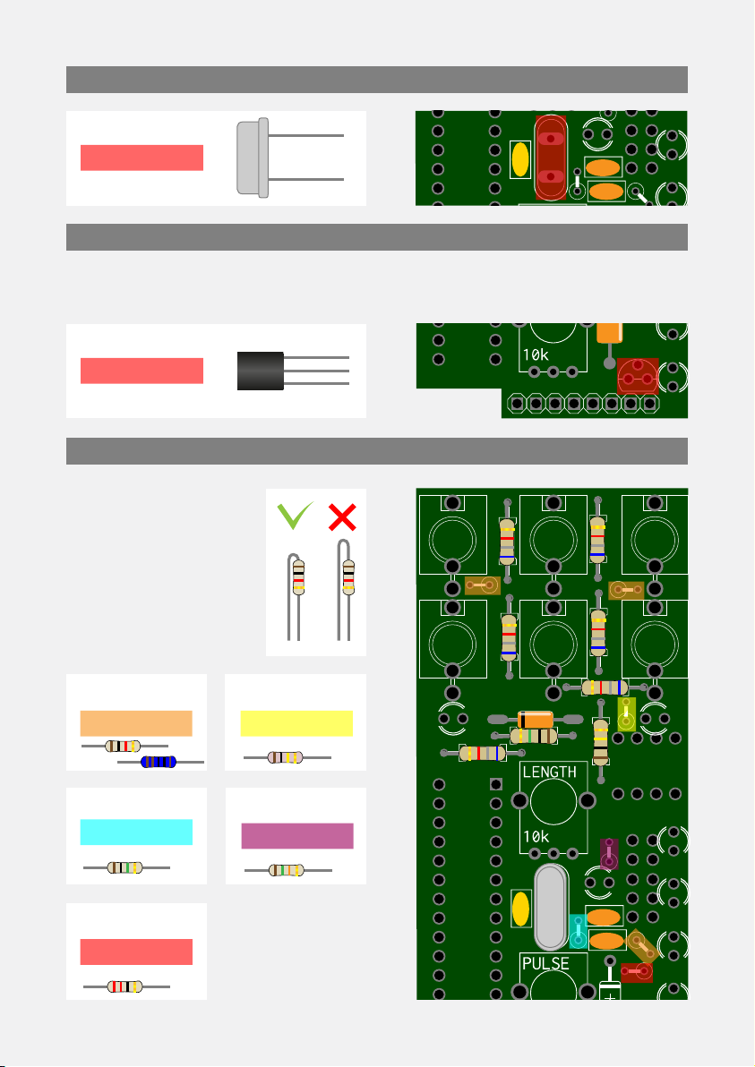
01. Components List + Tools
Resistors
6,8 kΩ
X6 — Pack 1/5
R7 → R10, R19, R20
100 kΩ
X6 — Pack 2/5
R15, 25, R3 → R6
1 kΩ
X5 — Pack 1/5
R11, R12, R16, R21, R26
1 MΩ
X2 — Pack 2/5
R1, R2
22 Ω
X1 — Pack 1/5
R27
15 kΩ
X1 — Pack 2/5
R14
Capacitors
22 pF
X2 — Pack 2/5
C1 + C2
100 nF
X1 — Pack 1/5
C3
Diodes
1N4148
X1 — Pack 1/5
D1
1N4742 Zenner
X1 — Pack 2/5
D10
Quartz
16 MHz
X1 — Pack 2/5
Q1
Jack Knurled Nuts
X6 — Pack 4/5
on jack connectors
Potentiometers
X2 — Pack 3/5
P1 & P2
Potentiometers Nuts
X2 — Pack 4/5
on potentiometer
Push Buttons
X4 — Pack 3/5
PB1 → PB4
Push Buttons Caps
X4 — Pack 3/5
on push buttons
M3 Panel Nut
X1 — Pack 4/5
on panel screw
M3 Screws
X2 — Pack 4/5
on panel
Chroma Caps Knobs
X2
on potentiometers
Top PCB (big)
X1 — Pack 5/5
Bottom PCB (small)
X1 — Pack 5/5
Aluminum Panel
X1
Power ribbon Cable
X1
Tools
Soldering Iron
Solder
Cutting Pliers
Masking Tape
LED’s
White LED
X1 — Pack 1/5
L+ LED
Amber LED
X7 — Pack 2/5
LED M1 → LED M5,
LED SM1 + LED SM2
Green LED
X2 — Pack 3/5
LED1 + LED2
IC’s
8 Pin IC Socket
X1 — Plastic Tubbing
ICS1
LM358 OpAmp
X1 — Plastic Tubbing
on ICS1
28 Pin IC Socket
X1 — Plastic Tubbing
ICS2
ATMEGA328
X1 — Plastic Tubbing
on ICS2
78L05
X1 — Pack 1/5
IC3
Miscellanous
Power Supply Header
X1 — Pack 3/5
PSH1
PCB Male Header
X1 — Pack 3/5
PH1
Jack Connectors
X6 — Pack 3/5
J1 → J6
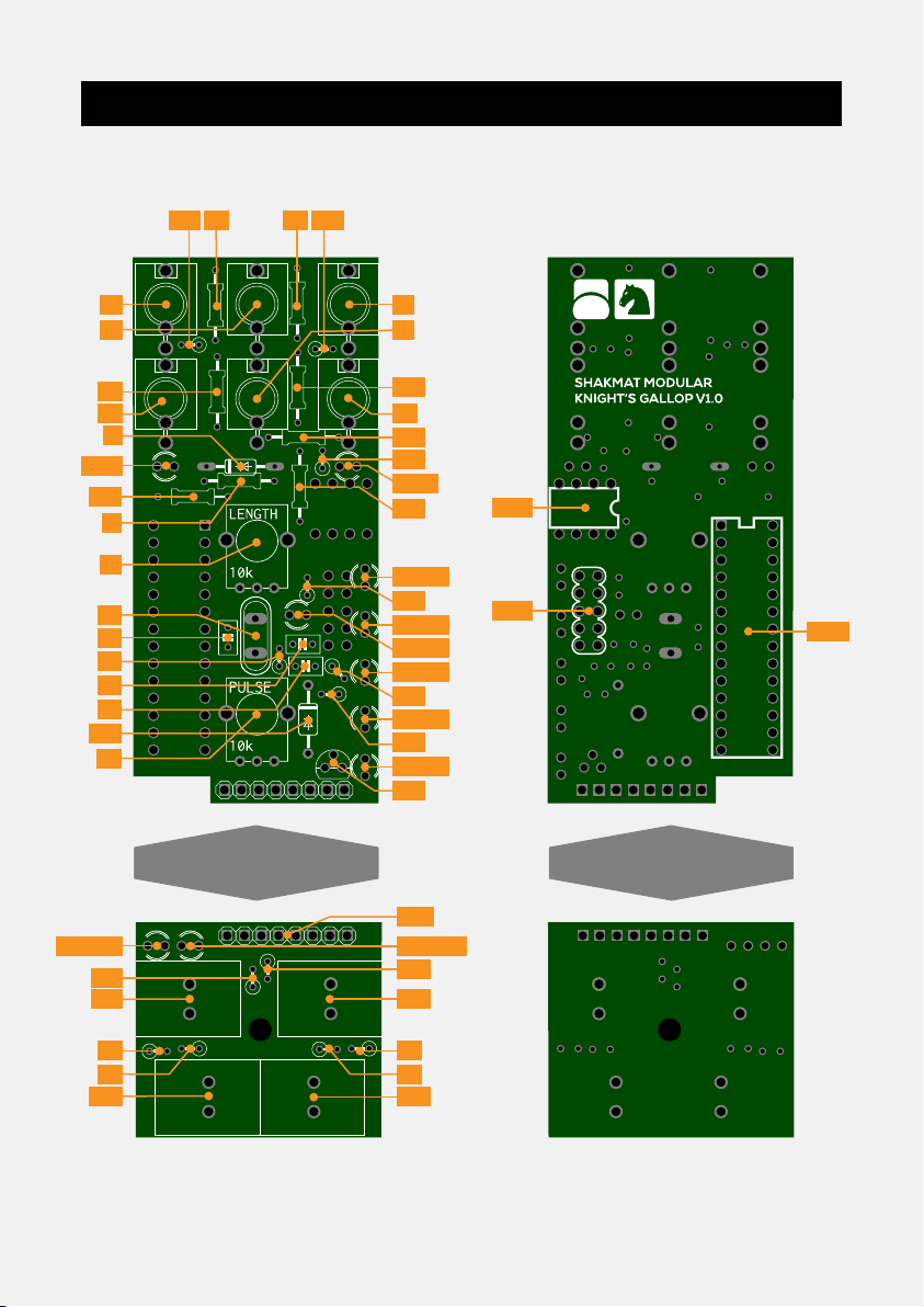
02. PCB Sides
Front Rear
R9R26 R16
R10
R20
R25
R14
R12
R27
L+ LED
LED2
R7
J4 J6
R8
R15
LED M1
LED M2 PSH1
ICS1
ICS2
LED M3
LED M4
LED M5
IC3
J1 J3
J2
D1
R2
R19
P1
P2
C3
C1
C2
D10
R1
Q1
J5
LED1
R3
PB1
PB2
R11
LED SM1
R5
R4
PB3
PB4
R21
PH1
LED SM2
R6
If you feel you're going to build this kit without looking at the steps, just
remember that it is very important to join the two PCB’s in a strict
parallel alignment. If you don't want the final build to have hard to press
buttons, please pay attention to that. We also recommand to have a look
to the steps 04_9 that require unexpected cuts for the potentiometers.
Don’t split the packs open & mix components, somes are virtually indistin-
guishable (like the 3 different color LED that all appear clear when inac-
tive). We strongly recommand to only take the component(s) you need
and let the other in their corresponding pack.
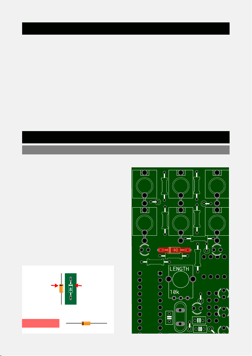
This build has two dierent
diodes : a tiny one and a bigger
one. This steps only concern
the 1N4148, that´s to say the
tiny one. Please note that the
diode orientation has to match
the PCB silkscreen. The white
line on the silkscreen has to
match the black bar on the
component, as on the
following picture.
03. Important Note
04. Top PCB Assembly
04_1. Diode 1N4148
White line
on PCB
Black line on
component
1N4148
X1 Pack 1/5
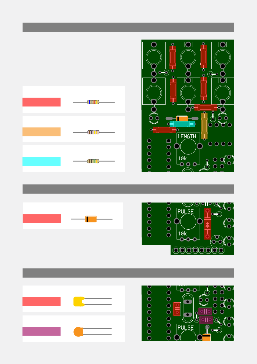
As in step 4_1, be carefull to the
diode polarity. You’ve to match the
silkscreen and component black line.
Here's a picture of the top PCB with
placement of the resistors by
values. There’s no polarity to
observe with resistors.
04_4. Capacitors
04_2. Laying Resistors
04_3. Zenner Diode
6.8k
100k
1M
X6
A
B
C
X1
X1
Zenner
X1
100nF
22pF
X1
A
B
X2
Pack 1/5
Pack 2/5
Pack 2/5
Pack 2/5
Pack 1/5
Pack 2/5 B
B
A
A A
A A
A
ACB
Only one leg of the
resistors have to be
bent before solde-
ring. Don’t bend the
leg too high or it will
cause short-circuit
with the panel.
Bend the middle leg of the 78L05. Then place the component on the PCB,
the flat side of it has to correspond to the flat side of the silkscreen.
04_5. Quartz
16 MHz
X1 Pack 2/5
78L05
X1 Pack 1/5
04_6. 78L05 Regulator
04_7. Standing Resistors
1k 100k
1M B
C
D
X3 Pack 1/5
X1 Pack 2/5
X1 Pack 1/5
X1 Pack 2/5
15k
X1 Pack 2/5
22
EE
AA
D
B
A
A
C
OR

There are 6 jack connectors, that
have to sit tight and flush with the
PCB. Be sure to push them all the
way through before soldering.
04_8. Jack Connectors
04_9. Potentiometers
X2 Pack 3/5
First you'll have to remove a little piece on the potentiometer as shown in
the picture. Then, you can place and solder them.
Cut
X6 Pack 3/5
Jack

Now, let’s flip the PCB and conti-
nue. We’re going to solder the two
ICs sockets. Be attentive to their
orientation. The red lines on the
picture show the right position.
04_10. IC Sockets
04_11. PCB Male Header
X1 Pack 3/5
Header
The PCB header is also mounted on the back of the top PCB. For now we
are taking care of the short legs side of the header. Be very carefull with
this piece : it has to lay completely flat with the PCB and perfectly perpen-
dicular. We recommand you to place de header and solder one leg then
verify it’s alignment before soldering the seven remaining legs.
X1 Plastic Tubbing

04_12. Power Supply Header
X1
Header
05. Bottom PCB Assembly
05_1. Standing Resistors
05_2. Push Buttons
1k
100k
A
B
X2
X4
Pack 1/5
Pack 3/5
Pack 2/5
AA
Button
X4 Pack 3/5
four buttons, then flip the PCB and
press it against your table in order
to ensure that every button is well
placed.
The buttons are easy to plug & solder but they need to be thoroughly
pushed on the PCB. Before soldering, we recommand to place the
BBB B
OR
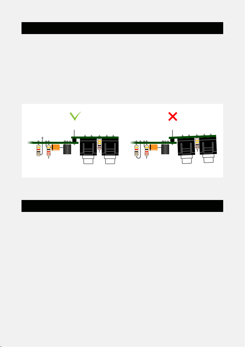
06. Top & Bottom PCB’s Assembly
07. LED’s Mounting
Be very carefull that the header you’re soldering is well passed through all
the bottom PCB holes and that the two PCB’s are perfectly horizontal. If
there is a gap between the header and the PCB’s, or if they’re not correc-
tly aligned, the push button could be pourly placed and hard to press.
As you did before, we recommand you to only solder one pin of the
header and check the alignment before soldering the seven other pins.
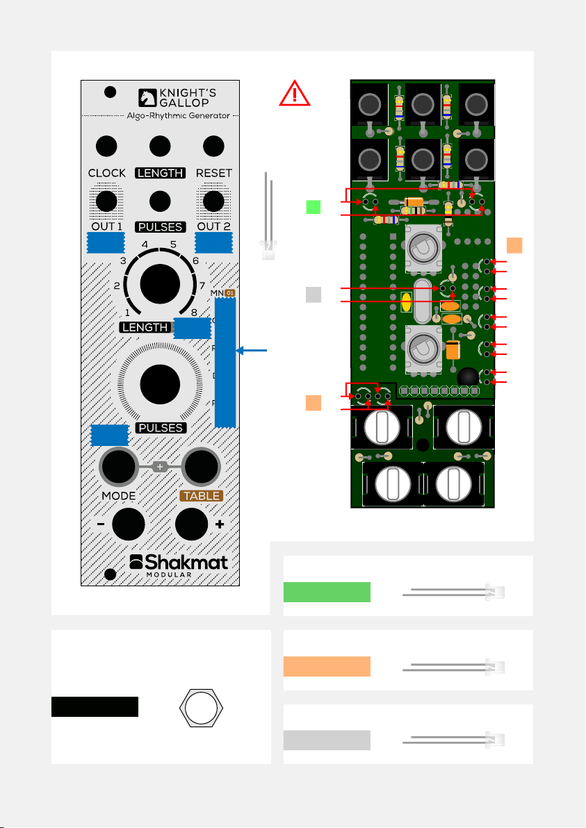
To get well soldered LED flush with the panel, you need to assemble the
front panel to the PCB. We recommand you to do this by finger tighten-
ning the two hex nuts on the potentiometers.
A good way to do this is to use masking tape to cover the panel LED holes.
Therefore you can place the LED on the PCB, assemble them with the
potentiometer nuts and push LED’s through the panel until they sit flush
and stick to the tape. Then you can solder them.
Be carefull with the LED polarity, the long leg is always the positive side.
Please refer to the following picture to know wich LED goes where. You
also need to pay attention to not mix LED’s from different packs, when
inactive the clear LED’s are very hard to differenciate from each other.
Masking
tape
LED
POLARITY
+-
+
-
+
+
-
-
+
-
+
-
+
-
+
-
+
-
Green
Amber
White
X2
A
B
C
X7
X1 Pack 1/5
Pack 2/5
Pack 3/5
Nuts
X2 Pack 4/5
A
C
B
B

08. IC’s, Nuts, Bolt & Caps
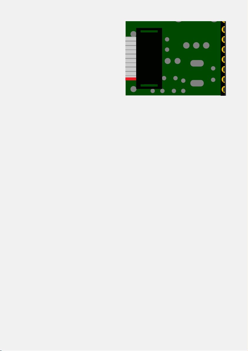
It’s now time to plug the IC’s in their sockets. Make sure the IC orientation
matches the socket orientation as on the following picture.
You can now place the six knurled nuts on the jack connectors and the M3
nut on the screw that is mounted on the back side of the panel. The func-
tion of this nut is to retain the bottom PCB to retreat when the buttons
are pushed.
Do not screw the M3 nut to far or it will push the bottom PCB out of it’s
parallelism with the top PCB and interfer with the buttons caps. Just
tighten it until it sits flush with the bottom PCB. To prevent this nut to
move over time, we recommand you to put a small amount of nail polish
on it. Some glue will also do the trick but can be very problematic to
remove if you need to unscrew this nut. Finally, mount the four buttons
caps and two potentiometers knobs. That’s it, you’ve finished !
X2 Plastic Tubbing
X6 Pack 4/5
X1 Pack 4/5
X4 Pack 3/5 X2
www.shakmatmodular.com
Plug the power cable and make
sure the red side of the ribbon
matches the -12V on the PCB.
Now let's plug the module in your
system and test it. The module
LEDs doesn't blink if the module
isn't running. So don't panic if
the modules seems quiet when
nothing is connected to it.
A fast and easy way to check if the module is working is to feed the clock
input with a trig gate signal and mangle with the potentiometers, both
LEDs should be blinking.
If ever you get some troubles or questions, send us an email at
support@shakmatmodular.com.
To download the Knight’s Gallop User Manual, go to our website and
navigate to the support section.
-12V
Table of contents


