Shakmat Mod Medusa User manual

12HP Eurorack Module Built & designed in E.U. www.shakmat.com

1
B
D
G
C
E
F
H
A
2
3
7
8
9
4
I
L
M
J
K
5
6
The Mod Medusa is an algorhythmic LFO. It delivers four
correlated or independent modulation channels synced to a
clock. Their timing fits rhythmic patterns, such as euclidean
ones famously used in trigger sequencing.
You won't run out of modulation waveforms anytime soon, as
the Mod Medusa has symmetry and waveshape controls. The
assignable inputs can be used to control each channel's
amplitude and mess with the wave sequencing using ratcheting
and track & hold.
Introduction
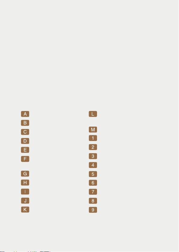
Mode / Assignable Gate
button & LEDs
Symmetry potentiometer
Clock input
VCA CV input
Length CV input
Symmetry CV input
Shape CV input
Density CV input
Reset input
Assignable Gate input
Outputs
Output activity LED
Tap tempo button
Unipolar button
Length potentiometer
Peak Sync button
Table / division
button & LEDs
Density potentiometer
Shape potentiometer
Shift left button
Shift right button
Length+/Menu button

The Mod Medusa requires a standard 2x5 pin eurorack power
cable. Make sure the red stripe on the cable matches the -12V
side of the Mod Medusa power header.
Installation
Sequencer
In a traditional Euclidean sequencer, the density sets the
number of pulses per cycle. Turned fully counterclockwise, it
mutes the sequencer. Turned clockwise, the sequencer
generates more and more triggers per cycle.
But Mod Medusa is not a trigger generator, so what is
different? In the case of our algorhythmic LFO, simply replace
the word trigger with waveform cycle, and you get the kind of
modulation presented in Fig. 01:
Fig. 01 — Euclidean sequencer vs euclidean LFO
Euclidean Sequencer
Note how each cycle
adapts its timing
to fit between
two consecutive
triggers.
Of course, the density
parameter is CV
controllable.
Euclidean LFO

Clock the module by inserting a clock signal into the clock input [1]
or by tapping the tap button [B]. Like a classic Euclidean sequen-
cer, the Mod Medusa gives several controls on the source pattern:
Length [D], Density [G], and Shift [I&J].
Pattern length can be set by the dedicated potentiometer [D] and
CV input [3]. Available lengths are 1 to 8 step. Pressing the Length+
button [K] allows access from 9 to 16 step long patterns.
It is possible to shift the sequence forward or backward by a step
using the two shift +/- buttons [I&J]. Holding the two buttons for
two seconds will remove any shifting, and the 4 mode LEDs [L] will
blink to confirm the shift reset. The reset input [7] causes the wave
sequence to return to the first step.
Waveforms
The Mod Medusa accurately controls generated waveform
symmetry [M] and waveshape [H]. Symmetry continuously balances
the rise and fall time of the generated waveforms. Shape morphs the
waveform continuously, scanning from a sigmoid, through
exponential, logarithmic, and linear shapes, to a sinusoidal curve.
Both parameters have a dedicated potentiometer and CV input.
Tables
Mod Medusa's heart relies on sequence tables originating in
algorithms used in our Knight's Gallop and White Gallop modules.
The current table can be changed using the button + LEDs menu [F].
Green LEDs :
1. As Straight As Possible
2. Classic Euclidean
3. Revised Euclidean
4. Anti-euclidean
Amber LEDs :
5. Descelerando
6. Accelerando
7. Divided Sequences
8. Fill Next
The uni button [C] switches between unipolar (0 – 5V) and bipolar
(- 5/ +5V) LFOs. In unipolar mode, the button is lit.
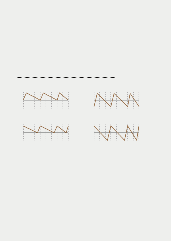
When the Peak Sync function [E] is off, the beginnings of the
waves are synced to the incoming clock signal. Activating it
synchronizes the peaks of the waves to the clock signal.
Changing polarity and peak sync applies to all four channels when
in correlated mode. In independent mode, each channel can have
different polarity and peak sync status.
Polarity & Peak Sync
The controls on the panel always set the parameters of the first
output. The other three outputs are correlated to the first channel,
giving different modulation signals with a “polyrhythmic” feeling.
This correlation changes based on the mode selected.
Modes
A. Correlated Outputs
Fig. 02 — How Peak Sync changes synchronization
Unipolar wave, Peak Sync Off
Unipolar wave, Peak Sync On
Bipolar wave, Peak Sync Off
Bipolar wave, Peak Sync On
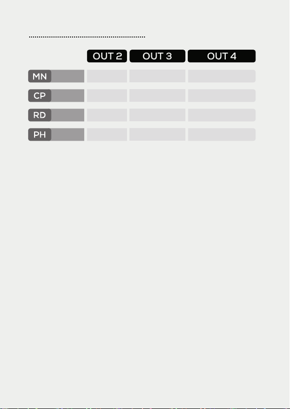
MN (main)
The sequences of channels 2, 3, and 4 are logically derived from
the channel 1 sequence.
CP (compute)
The sequences of channels 2, 3, and 4 are mathematically
associated with those of channel 1. For example, in L/2 & C/2, if
the channel 1 sequence is 12 steps long with 4 cycles, the
associated sequence has 12/2 = 6 steps length with 4/2 = 2
cycles.
RD (random)
Channel 2 and 3 randomly switch to the L/2 & C/2 pattern with a
low and high probability, respectively, while the channel 4
sequence is fully random.
PH (phase)
Each channel is shifted by L/4. With certain settings, this gives a
feeling of quadrature modulation.
In independent mode, you can individually set each channel's
parameters: length, density, shift, shape, symmetry, table, polarity,
and peak syncing.
B. Independent Outputs
Fig. 03 — Correlated outputs modes
BackwardMain
Compute
Random
Phase
Inverted 1 cycle per length
L/2 & C/2 2xL/3 & 2xC/3 L-C
Soft Fill Hard Fill Random
L/4 shift L/2 shift 3L/4 shift

The options menu allows to divide the incoming clock, assign a
function to the Assignable Gate input [8], and assign which
channels are impacted by the VCA input [2].
To enter, press the Length+/Menu button [K] for two seconds. The
Uni and Peak Sync buttons [C&E] start blinking. To exit, press the
Length+/Menu button for two seconds.
Menu
The Gate Input [8] can be assigned to perform one of eight
different options. You can toggle between them while in options
menu, using the Assignable Gate button [L] and LEDs:
A. Assignable Gate Input
When assigned to a rachet, receiving a gate at the beginning of an
LFO cycle will cause the cycle rate to be multiplied by the ratchet
ratio.
In independent mode, CV inputs
only act on channel 1.
Press the Mode button [L] for two seconds. A mode LED [L] starts
blinking, indicating which channel is edited. Use the Mode button
to switch between channels. Use the controls to set the channel
parameters. Press the Mode button for two seconds to exit.
Ratchet
x2
Ratchet
x4
Ratchet
x3
Random
Ratchet
Steady LED
Ratchet
Accelerando
Track
& Hold
Ratchet
Deccelerando
One-Shot
Blinking LED

The module's current state can be stored by pressing and holding
the unipolar button [C] for two seconds. This stores both the
correlated or independent mode settings.
Current State Storing
When assigned to Track & Hold, the outputs track the LFO cycles
normally while the incoming gate is high, and hold their value
when the gate is low. Using triggers instead of gates will give a
Sample & Hold feeling, better suited to create stepped values.
When assigned to One-Shot, the LFO cycles will only start when a
gate is received at the beginning of the cycle.
While in the options menu, you can use the shift buttons [I&J] and
the activity LEDs [A] to assign which channels the VCA input [2]
controls. The input is unipolar (0-5V) and normalized to 5V.
B. VCAs
While in the options menu, you can use the table button [F] and
LEDs to apply a division of the incoming clock signal (1 to 8).
C. Clock Divider
You can use the tap button [B] to replicate a gate
received at the A Gate input [8]. In the options
menu, simultaneously press the mode button [K]
and the tap button [B] to change between having
the tap button acting as a tap tempo (green) or a
manual gate (red).

Specifications
Size
12 HP
Depth
21 mm
Current Draw
55 mA @ +12V
30 mA @ -12V
CV inputs
-5 to +5V
VCA CV input
0 to +5V
CV outputs
-5 to +5V
Assignable gate input
-5 to +5V
www.shakmat.com
Other manuals for Mod Medusa
1
Table of contents
Other Shakmat Recording Equipment manuals


Popular Recording Equipment manuals by other brands


Odiseimusic
Odiseimusic Travel Sax 2 user manual

Entrematic
Entrematic Ditec COM400MKB instructions

PULSEEIGHT
PULSEEIGHT P8-AD340 Quick reference guide

AL Tech
AL Tech PVR 6600 instruction manual

i3 International
i3 International 4i00XX Series Quick connection guide

B-Tech
B-Tech BT8500 Assembly and installation