Shakmat Harlequin's Context User manual

Shakmat
Harlequin’s Context
Building Guide
12HP Eurorack Module Built & designed in E.U. www.shakmat.com

Table of contents
www.shakmat.com •
Preamble
Component list & necessary tools
PCB details
Top PCB assembly
4.1 Front
4.1.1 Electrolytic capacitors
4.2 Back
4.2.1
Male headers (1x4 pin)
4.2.2
Power header (2x8 pin)
Tactical Plan assembly
Top PCB final assembly
6.1 Front
6.1.1 Jack connectors
6.1.2
Potentiometers & nuts
PCB stacking
Bottom PCB assembly
8.1 Front
8.1.1 Push buttons & display
Front panel preparation
LED mounting
Finish
First startup routine
Debug
.................................................................................................................................. 2
................................................................................... 3
............................................................................................................................4-5
................................................................................................................ 6
.............................................................................................................................. 6
.................................................................................... 6
.............................................................................................................................. 7
................................................................................ 7
............................................................................... 8
......................................................................................................... 9
..................................................................................................... 10
............................................................................................................................ 10
............................................................................................. 10
................................................................................ 11
......................................................................................................................... 12
....................................................................................................... 13
............................................................................................................................ 13
................................................................................ 13
..................................................................................................... 14
.................................................................................................................. 15-16
........................................................................................................................................ 17
.............................................................................................................. 18
....................................................................................................................................... 19
1.
2.
3.
4.
5.
6.
7.
8.
9.
10.
11.
12.
13.

www.shakmat.com •
02/19
Thank you for purchasing a Shakmat DIY kit !
We spare no effort in our kit packing process to prevent any mistakes or
missing parts. In this document as well, we do our best to describe the assem-
bly process in the most practical and comprehensive way. If by any chance
there is a missing/damaged part in your kit or if you have any suggestion, feel
free to contact us via shakmat.com.
We strongly advise you NOT to spill all the bags open and mix their
components. Some of them are virtually indistinguishable (like LEDs that
all appear clear when inactive). We recommend to only take the neccesary
component out of its bag, or to empty the bags in separate & marked contai-
ners. For each step, next to the component’s graphic representation, there is a
reference indicating where to find it (i.e. P1 for Pack 1, or LP for Loose Part).
The assembly process will be dramatically simplified if you follow the order
defined by this building guide. We tested various orders of steps before finding
the most convenient, and the one presented here is the best!
1. Preamble

www.shakmat.com •
03/19
Pack 1
4x Amber LEDs
1x 7 segment display
8x Push buttons
8x Round push button caps
4x M3 metal screws
2x M3 nylon screws
2x 14mm nylon spacers
6x Jack connector nuts
4x Metal potentiometer nuts
Pack 2
2x 20 pin male header
2x 20 pin female header
1x 2x8 pin power header
4x 4 pin male header
4x WhiteLEDs
4x Green LEDs
3x 22 µF electrolytic capacitors
4x Metal potentiometers
6x Jack connectors
2. Component list & necessary tools
Pack 3
1x Top PCB
1x Bottom PCB
1x Tactical Plan
Loose parts
1x Front Panel
4x Black rubber knobs
1x Power cable
1x User manual
1x Cheat Sheet
Necessay tools
Soldering iron
Solder
Cutting pliers
Masking tape

www.shakmat.com •
04/19
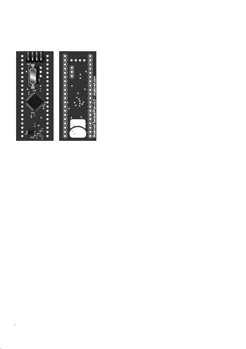
3. PCB details
Top PCB
Front & back
Bottom PCB
Front & back
C1
C2
C3
-12V
www.shakmat.com •
05/19
Tactical Plan
Front & back

www.shakmat.com •
06/19
C1
C2
C3
4. Top PCB assembly
Solder the three 22µF capacitors.
You must pay attention to the orienta-
tion of these components. The long
leg indicates the positive side,
therefore it has to match the + sign
on the PCB silkscreen.
4.1 Front
4.1.1 Electrolytic capacitors (x3) P2
-12V
www.shakmat.com •
07/19
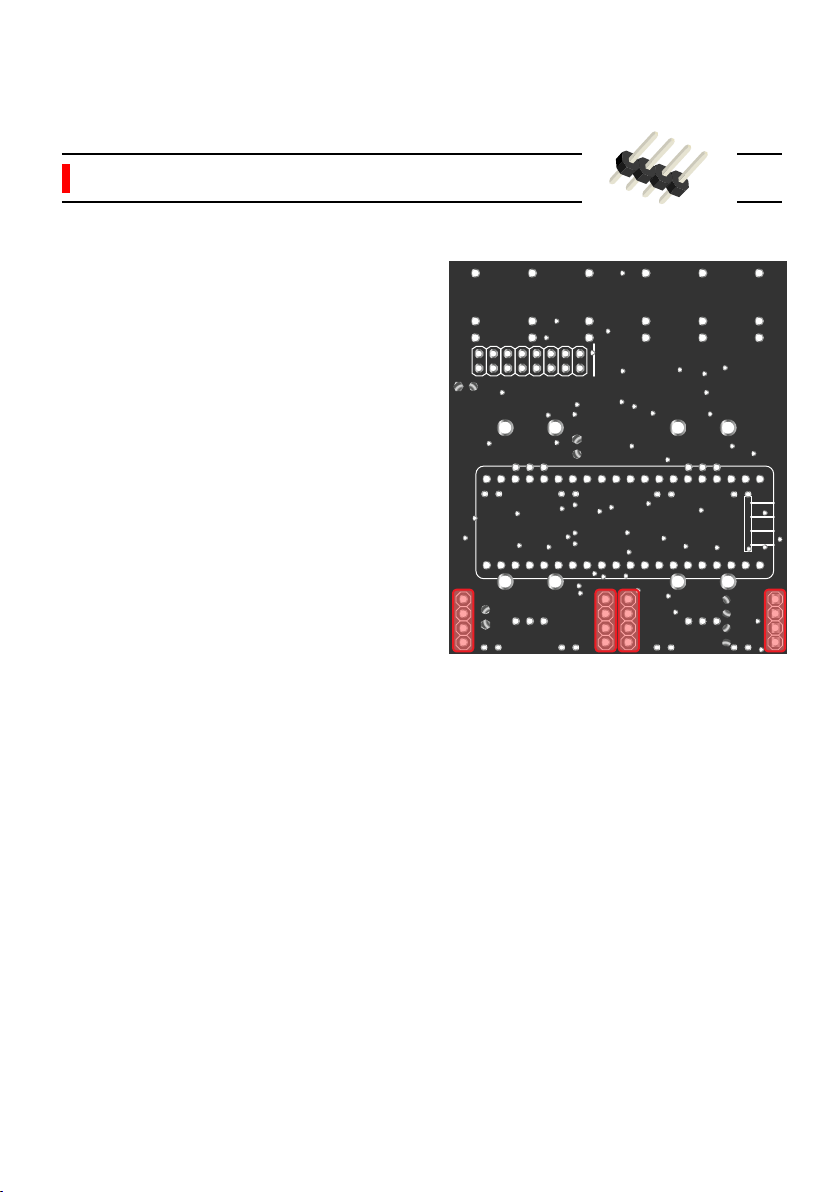
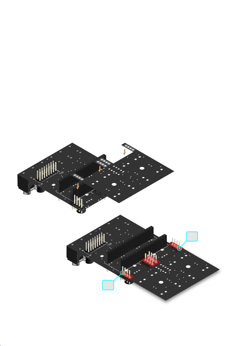
Flip the PCB and place a 4 pin male
header, with the short pin side
through the hole. We will solder these
four headers one by one. Be sure to
lay them flat and upright. Those
headers will later join the two PCBs
together so they need to be perfectly
perpendicular.
We recommend you only solder one
of the pins. Then reheat your solde-
red point and simultaneously press
the plastic part of the header against
the PCB until it’s flat. Take off the
soldering iron but keep pressing.
Avoid touching the pins themselves
because they will become hot very
quickly and move out of alignment
within their plastic bracket. Once you
are satisfied with you placement,
solder the remaining pins.
4.2 Back
4.2.1 Male headers (4pin) (x4) P2
www.shakmat.com •
08/19
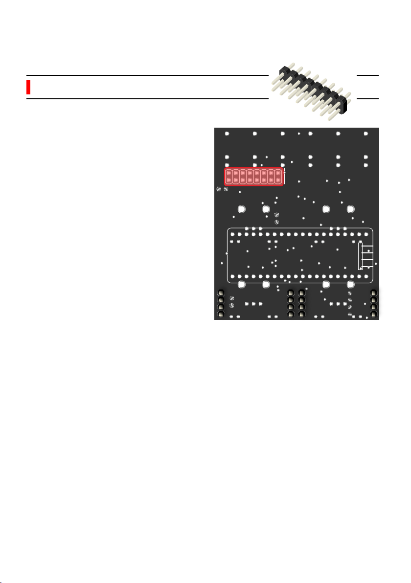
Place the power header, the short pin
side in the holes and solder only one
of the pins. Check the alignment and
correct with the same method as for
a single row header. Then, once your
component is upright and flat on the
PCB, solder the remaining pins.
4.2.2 Power header P2
-12V

www.shakmat.com •
09/19
2x
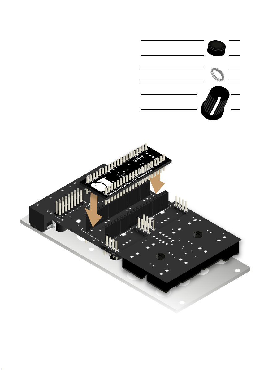
5. Tactical Plan assembly
5.1 Male & Female headers (x2) P2
Now, we are going to stack the Tactical Plan with the top PCB. For this we
use two 20 pin pairs of male & female headers. First assemble the headers,
then place them on the Tactical Plan, female side down. Then assemble the
two boards toghether and solder one pin, on each side, for each header. Once
the PCBs are held together and correctly aligned, you can solder all the remai-
ning points.
Be VERY careful with the soldering of the female part of the headers. Once
the potentiometers will be in place, those solder points will be inaccessible.
After everything is well soldered, disconnect the Tactical Plan and proceed to
the next step with the top PCB.

www.shakmat.com •
10/19
Flip the PCB around and solder the
six jack connectors. Be sure to lay
them completely flat on the PCB
before soldering. If those jacks aren’t
perpendicular, the front panel will be
very hard to mount.
If one of the jacks is not perfectly
perpendicular with the PCB, you can
reheat the pads and push it down
with your thumb to re-align.
6.1 Front
6.1.1 Jack connectors (x6) P1
6. Top PCB final assembly
C1
C2
C3
www.shakmat.com •
11/19
C1
C2
C3
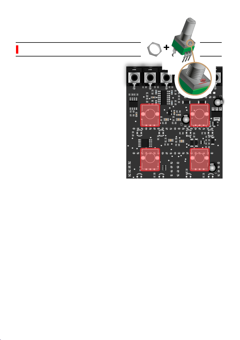
Before soldering, you will have to cut
a little metal piece off the top of each
potentiometer, as shown in the
picture. This little stud prevents the
front panel from sitting properly. Use
some small & sharp cutting pliers for
this task.
Then, place the 4 potentiometers on
the PCB. Be sure that no metal part
of the potentiometer touches a
soldering point from the previous
step. Mount the front panel and
tighten the potentiometers nuts (this
will ensure a proper placement of
the pots) and then solder them.
Once you have soldered everything,
remove the nuts, the front panel and
proceed to the next step.
6.1.2 Potentiometers & nuts (x4) P1&P2
Cut!
4x
www.shakmat.com •
12/19
7. PCB stacking
It’s now time to join and solder the two PCBs together. Be very careful during
this step. If you solder every pin and the PCBs arn’t well aligned, you will likely
not be able to correct it and will encounter all sorts of problems on your way to
the end of this build.
The first step is to assemble the two PCBs as shown above, and only solder
the first pin of the small vertical header. It is vey important that you firmly hold
the two PCBs against each other while soldering this point. There must be no
gap between the PCBs and the header’s black plastic part between them.
Once you’ve soldered the first point, you can move on to the second header
as shown below. Repeat the same procedure as for the first point for all of the
four points listed. Once they are all perfect, without any gap between the
PCBs and headers, you can solder every remaining point.
02
01
www.shakmat.com •
13/19
8.1 Front
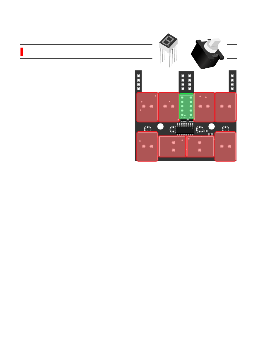
8.1.1 Push buttons (x8) & display P1
8. Bottom PCB assembly
Before placing and soldering the
push buttons, place the 7 segment
display on the PCB. Pay attention to
the orientation, the dot is on the
bottom line. Sometimes, its legs can
be a little bent thus hard to get
through the holes. So place the
display but don’t solder it and then
the buttons.
The buttons need to be upright and
pushed well against the PCB. An
imprecise mounting will result in a
cap scrapping against the front
panel. We recommend you to place
the buttons, then flip the PCB
(holding the buttons in place with a
piece of cardboard) and press it
against a table.
At the final step, if a button is not well
aligned with the front panel, you can
gently re-heat its solder points and
push it into alignment.

www.shakmat.com •
14/19
9. Front panel preparation
Place some masking tape over every LED
hole on the front panel. Make sure not to
block any other component’s hole with the
tape. The LEDs are special flat top models
intended to be mounted flush with the front
panel. The masking tape will help you to
do this neatly.
You also need to screw the two nylon
spacers on each of the two studs at the
back of the front panel. Screw them until
the end of the thread. These spacers will
assure the stability & alignment of the
PCB’s bottom half.
Nylon spacer (x2) P1

www.shakmat.com •
15/19
10. LED mounting
Placing the LEDs requires a
specific orientation due to their
polarity. The long legs are the
positive side and they all go into
the left holes of the top PCB. For
the bottom PCB, place the long leg
in the upper hole.
Place all the LEDs through the
PCBs. Be aware of LED colors
(some of their legs can be coloured
to help you differenciate them).
LED POLARITY!
Green LEDs ( Ax4) P2
White LED ( Cx4) P2
Amber LEDs ( Bx4) P1
C1
C2
C3

www.shakmat.com •
16/19
Potentiometer nuts (x4) P1
Nylon screw (x2) P1
Assemble the PCBs & front panel with the four nuts on the potentiomers
and the two nylon screws through the bottom PCB into the spacers. Once
everything is well secured, push every LED through their hole until they sit
flush with the panel and stick to the tape. Once they are all in place, you
can solder and trim the legs.
Finally, solder only one leg of the 7 segment display and check that it sits
well against the front panel window. Triple check the display alignment
through the front panel window. When all of its legs are soldered, it is
imposible to correct its placement. Once it’s nicely placed, you can solder
the remaining legs of the display and trim them.
www.shakmat.com •
17/19
11. Finish
You’re almost done! The last thing
to do is to place the tactical plane
on the top PCB. Pay attention to
the orientation. The Shakmat logo
must be on the left side as shown
here.
Place all the push button caps.
Tighten the knurled nuts on the
jack sockets. Push the four knobs
onto their metal potentiometer.
Button caps (x8) P1
Jack nuts (x6) P1
Knobs (x4) LP

www.shakmat.com •
18/19
12. First startup routine
Make sure all the potentiometers are fully counterclockwise when turning
on your Harlequin’s Context for the first time. Plug in the power cable and
make sure the red side of the ribbon matches the -12V on the PCB. Now let's
plug the module into your system and test it. The module identifies the first time
it turns on and automatically starts the calibration, test and factory reset
routines.
Turn on your rack. The Harlequin’s display shows a “C” for calibration.
• Patch the channel A output into the CV input and press the Scene 1 button
• Patch the channel B output into the CV input and press the Scene 2 button
• Patch the channel C output into the CV input and press the Scene 3 button
• Patch the channel D output into the CV input and press the Scene 4 button
The calibration is now done and the Harlequin automatically switches to the
test routine :
• Each output produces a ramp (saw up LFO)
• CV input positive voltage values are displayed on the 7 segment display
• When an active gate is received in the gate input, the screen turns off
Therefore, patch each channel’s output into the CV input (the 7 segment
display will give values from 0 to F). Patch one of the outputs into the gate
input (the 7 segment display should slowly blink).
To test the white and amber LEDs, press each of the eight buttons of your
Harlequin’s Context. When pressed, each button lights an individual LED up.
The green LEDs show the potentiometer value by their intensity. Turn all the
potentiometers fully clockwise until all the green LEDs are fully on. You will exit
the test routine when all the potentiometers are fully clockwise.
Now hold the first Scene button until the display shows the letter “F”.
Press the Store button to start the Factory Reset routine. This operation will
clear all the non volatile memory, slot by slot, and the display will show the slot
currently being cleared (from 1 to G).
Once the Factory Reset routine is done, the module will start normally.

www.shakmat.com •
18/19
13. Debug
The module does not turn on
Check the orientation of the Tactical plan.
Re-check the electrolytic capacitors and power cable orientation.
The module is stuck in the calibration routine, or one or several outputs
are not working
Check the jack connectors & Tactical plan soldering.
One or several LEDs are not working
Check the LEDs solder points and LED orientation.
Check the Tactical Plan headers solder points.
For the amber LEDs, check the PCB to PCB headers solder points on both
PCBs.
One or several potentiometers are not working
Check the solder points and Tactical Plan headers solder points
One or several buttons are not working
Check the buttons solder points.
Check the PCB to PCB headers solder points on both PCBs.
The 7 segment display is not working
Check the display solder points.
Check the PCB to PCB headers solder points on both PCBs.
Table of contents
Other Shakmat Recording Equipment manuals


