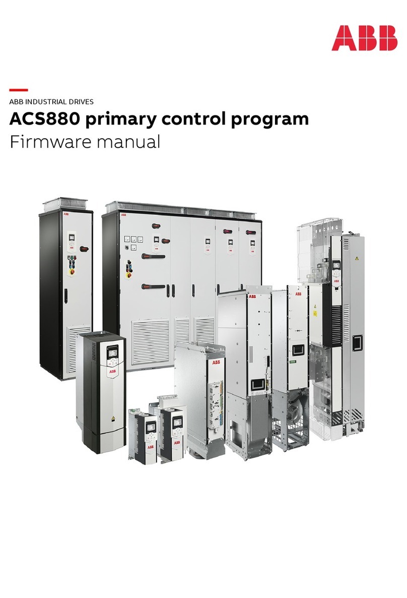
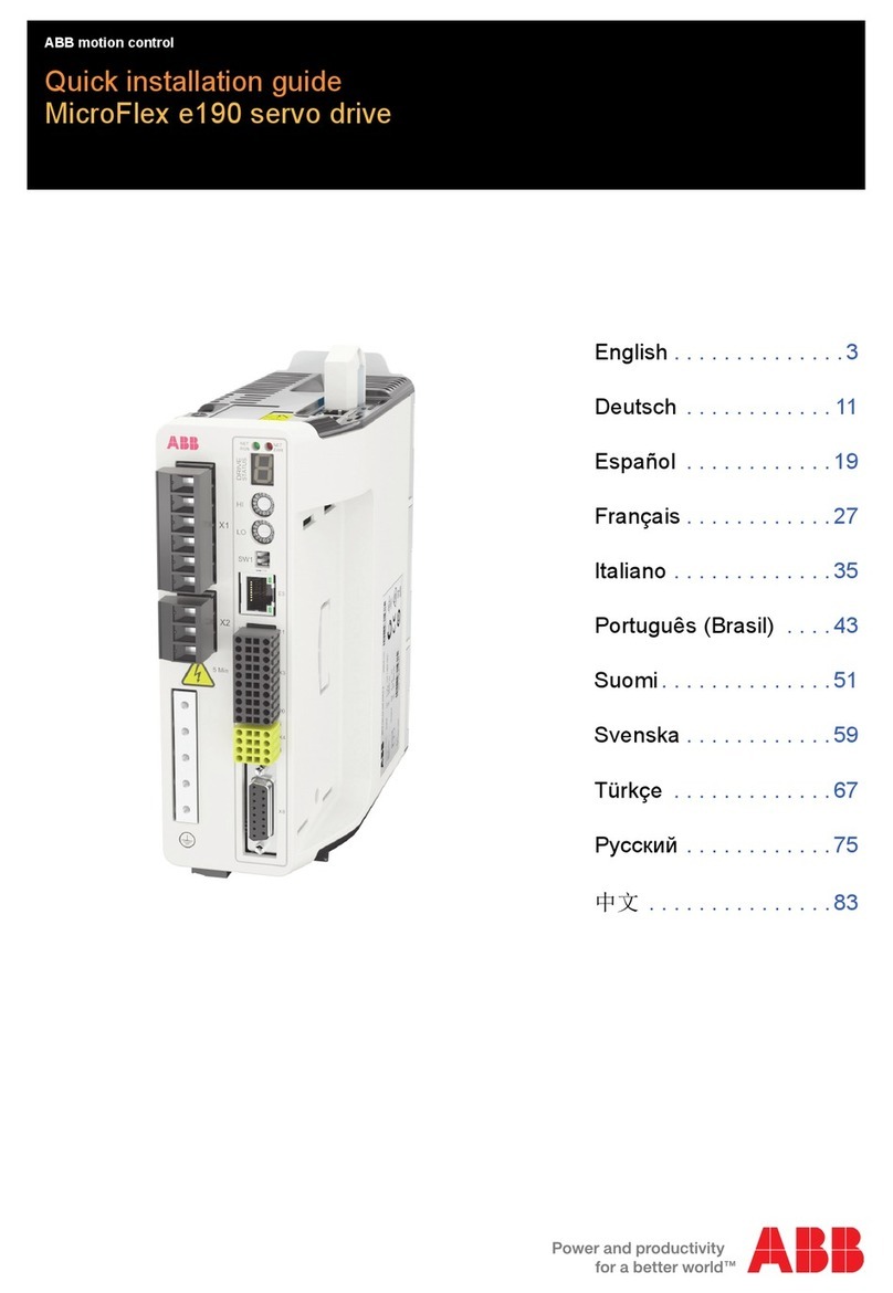
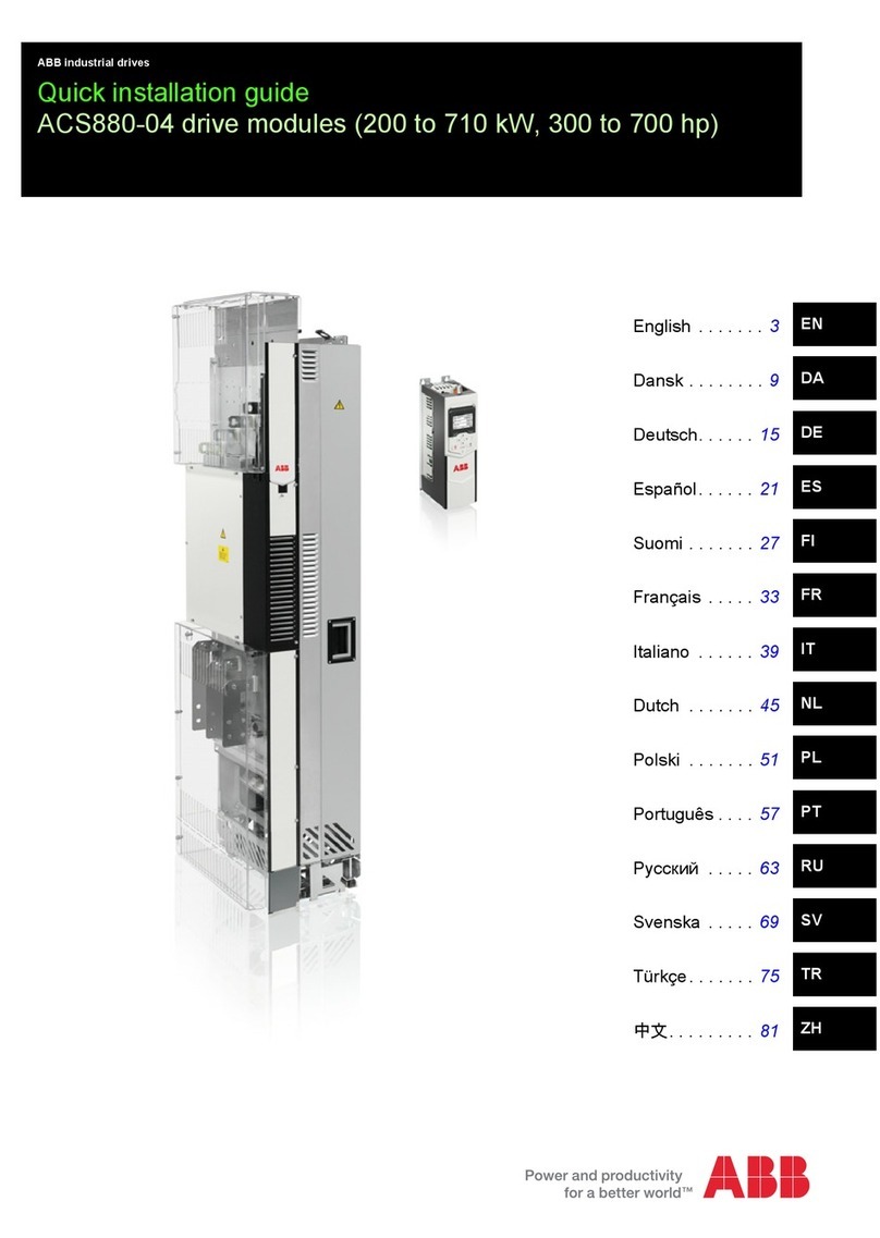
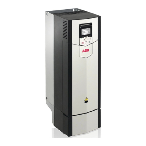
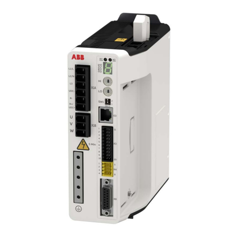
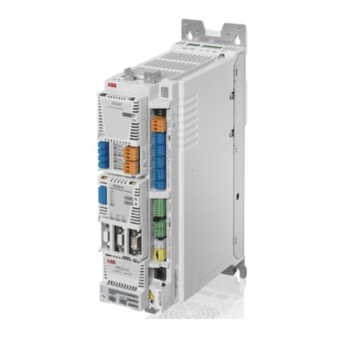
ABB MicroFlex e190 User manual

List of related manuals in English
You can find manuals and other product documents in PDF format on the Internet. See section
Document library on the Internet on the inside of the back cover. For manuals not available in the
Document library, contact your local ABB representative.
* MicroFlex e190 firmware build version that supports the option card: Build 5900.4.0 and later.
3AXD50000037325 Rev D
MUL
EFFECTIVE: 2020-03-06
© 2020 ABB Beijing Drive System Co., Ltd. All Rights Reserved.
Drive hardware manuals and guides Code (English)
MicroFlex e190 User’s manual 3AXD50000037326
MicroFlex e190 Wall chart 3AXD50000037323
Certificates
MicroFlex e190 & OPT-SIO-1 EU Single Declaration of Conformity 3AXD10000540159
MicroFlex e190 STO (TÜV) Certificate 3AXD10000540318
MicroFlex e190 UL Certificate 3AXD10000540319
Option manuals and guides
OPT-MF-200 Encoder Breakout Quick installation guide 3AXD10000692233
OPT-MF-201 Resolver Adapter Quick installation guide 3AXD10000688314
OPT-SIO-1 Option Card* User's manual 3AXD50000351336
OPT-SIO-1 Option Card Quick installation guide 3AXD50000296361

Quick installation guide - MicroFlex e190
3
Quick installation guide -
MicroFlex e190
Introduction
This guide contains the very basic information
about the mechanical and electrical installation
of the MicroFlex e190 drive module. For
complete documentation see the
MicroFlex e190 User’s Manual (code:
3AXD50000037326 [English]).
Safety instructions
WARNING! All electrical
installation and maintenance work on
the drive should be carried out by
qualified electricians only.
WARNING! Operation of this
equipment requires detailed
installation and operation instructions
provided in the Installation/Operation
manual intended for use with this product. It
should be retained with this device at all times.
A hard copy of this information may be ordered
at +358 10 22 11 or your local ABB sales office.
Never work on the drive, the braking chopper
circuit, the motor cable or the motor when input
power is applied to the drive. After
disconnecting input power, always wait for 5
minutes to let the intermediate circuit
capacitors discharge before you start working
on the drive, control cabling, motor or motor
cable. Even when input power is not applied to
the drive, externally supplied control circuits
may carry dangerous voltages. Always ensure
by measuring that no voltage is actually
present.
• A rotating permanent magnet motor can
generate a dangerous voltage. Lock the
motor shaft mechanically before connecting
a permanent magnet motor to the drive, and
before doing any work on a drive system
connected to a permanent magnet motor.
• The MicroFlex e190 is an IP20 (UL open
type) drive to be used in a heated, indoor
controlled environment. The drive must be
installed in clean air according to enclosure
classification. Cooling air must be clean, free
from corrosive materials and electrically
conductive dust. See the User’s Manual for
detailed specifications.
• The MicroFlex e190 must be installed where
the pollution degree according to UL and EN
61800-5-1 shall not exceed 2.
• The maximum ambient air temperature is:
1.6 A model: 45 °C (113 °F) at rated current.
The current is derated for 45 to 50 °C (113 to
122 °F). See user’s manual.
3 A - 9 A models: 55 °C (131 °F) at rated
current. No current derating is required.
• Motor overtemperature sensing is not
provided by the drive.
• The drive is suitable for use in a circuit
capable of delivering not more than 5,000
rms symmetrical amperes, 240 V maximum,
when protected by CC class fuses, rated
max. 20 A.
• The cables located within the motor circuit
must be rated for at least 75 °C (167 °F) in
UL-compliant installations.
• Use 75 °C copper wiring only.
• The input cable must be protected with
fuses. Suitable IEC (class gG) and UL (class
CC) fuses are listed in the Technical data
section of the MicroFlex e190 User’s
Manual.
• Integral solid state short circuit protection
does not provide branch circuit protection.
For installation in the United States, branch
circuit protection must be provided in
accordance with the National Electrical Code
(NEC) and any applicable local codes. To
fulfill this requirement, use the UL classified
fuses.
Quick installation guide - MicroFlex e190
4
• For installation in Canada, branch circuit
protection must be provided in accordance
with Canadian Electrical Code and any
applicable provincial codes. To fulfill this
requirement, use the UL classified fuses.
• For use in Canada: Transient surge
suppression shall be installed on the line side
of this equipment and shall be rated 240 V
(phase to ground), 240 V (phase to phase),
suitable for overvoltage category III, and
shall provide protection for a rated impulse
withstand voltage peak of 2.5 kV.
• The drive provides overload protection in
accordance with the National Electrical Code
(NEC). See the User’s Manual for overload
protection settings.
• The drive can provide an overload current of
300% of rated current for a maximum of 3 s.
See user manual.
Mechanical installation
Fasten the drive module to the mounting base
using screws through the two mounting holes.

Quick installation guide - MicroFlex e190
5
Dimensions
72
(2.83)
155
(6.10)
200*
(7.87)
7
(0.28)
5
(0.2)
6
(0.24)
188.4
(7.42)
200
(7.87)
223*
(8.78)
Ø 5
(0.20)
5
(0.20)
5
(0.20)
Ø 12
(0.47)
* Approximate dimensions. Allow extra
space for feedback and other control
cables.
Weights:
1.6 A: 1.65 kg (3.64 lb)
3 A: 1.70 kg (3.75 lb)
6 A: 1.75 kg (3.86 lb)
9 A: 1.75 kg (3.86 lb)
Unit: mm (inches)

Quick installation guide - MicroFlex e190
6
Electrical installation
Notes:
(1) If shielded supply (input) cable is used, and
the conductivity of the shield is less than 50%
of the conductivity of a phase conductor, use a
cable with a ground conductor or a separate PE
cable.
(2) For motor cabling, use a separate ground
cable if the conductivity of the motor cable
shield is less than 50% of that of a phase
conductor and the cable has no symmetrical
ground conductors.
(3) MicroFlex e190 can be powered from a DC
supply. See user’s manual.
(4) AC supply,1-phase 200...240 V or 3-phase
200...240 V phase-to-phase (±10%).
Power cabling: input
• Attach the included terminal blocks to the
drive.
• Connect the supply, resistor (if present) and
motor cables to the appropriate terminals of
the drive.
• Strip the power cables so that the shields are
bare at the cable clamps.
0.5...0.6 N·m
(4.4...5.3 lbf·in)

Quick installation guide - MicroFlex e190
7
Power cabling: motor output
Ground the motor cable shield.
Control cabling
1
0.5...0.6 N·m
(4.4...5.3 lbf·in)
2
Cable clamp on bare shield.
PE/Ground connection.
1
2
4
Use shrink tubing or tape to contain strands.
Remove outer jacket of cable at clamp to
expose cable screen
3
4
3

Quick installation guide - MicroFlex e190
8
Wire sizes and tightening torques:
X1A: Dinkle EC762V-B3253206P-BK
X1B: Dinkle EC762V-B3253203P-BK
0.2...6.0 mm2 (30*...10 AWG)
* Minimum size for UL installations is 14 AWG.
Torque: 0.7 N·m (6.2 lbf·in)
X2: Phoenix Contact MVSTBR 2,5HC/ 2-ST-5,08
0.2...2.5 mm2(24...12 AWG)
Torque: 0.6 N·m (5.3 lbf·in)
X3, X4: Weidmüller B2L 3.50/20/180,
Weidmüller B2L 3.50/8/180
0.2...1.0 mm2(28...16 AWG)
Notes:
The wiring shown is for demonstrative purposes only.
Complete information for all connectors, including X7
and X8, is provided in MicroFlex e190 User’s Manual
(code: 3AXD500000373236).
E1/E2
EtherCAT or IN E2
Ethernet POWERLINK OUT E1
X1A
200...240 V AC ±10%
input
L1 1
L2 2
L3 3
DC bus- UDC- 4
Brake resistor R- 5
DC bus+ / Brake res. R+/UDC+ 6
X1B
Motor output
U1
V2
W3
E3
Ethernet host (PC) 1
X3 X3
1DO0- DO0+ 11
2 DO2- DO2+ 12
3 DO1- DO1+ 13
4 DI2- DI2+ 14
5 DI3- DI3+ 15
6 DI1- DI1+ 16
7 DI0- DI0+ 17
8AGND AO0 18
9 AI0- AI0+ 19
10 Shield Shield 20
E2
Connectors
E1
X1A
X1B
E3
X3
X4
X8
X7
X2
Universal encoder input
supports multiple
feedback types.
See MicroFlex e190
User’s Manual.
X4 X4
1STO1 STO1 5
2STO2 STO26
3 SGND SGND 7
4 24 V out 24 V out 8
Safe Torque Off: Both circuits must be closed for the drive to start.
All connections are duplicated for easy wiring.
X2
(Optional) External
power input: 24 V, 1 A
0 V 1
+24 V IN 2
M
Example:
STO input
using internal
24 V supply
Example:
STO input
using external
24 V supply
Safe Torque Off
Input/ Output
Real time Ethernet fieldbus
Incremental encoder
in/out
Feedback voltage selector
Optional 24 V supply
Ethernet host (PC)

Quick installation guide - MicroFlex e190
9
E1 / E2: Ethernet port configuration
The rotary switches are read once at start-up.
The switches select the mode of operation for
the E1 and E2 Ethernet fieldbus connectors on
the top panel of the drive.
SW1: Mode and IP address selection
The linear switches are read once at start-up.
The switch 2 selects the mode of operation for
the drive. The switch 1 selects IP address
assignment for the E3 host port.
X7: Incremental encoder in / out
The secondary incremental encoder input/
output connection provides A/B channels and a
Z index channel.
X8: Motor feedback in
The primary incremental encoder input
connection provides A/B/Z channels and Hall
signals.
More connections for serial interfaces and extra
incremental encoder, see MicroFlex e190
User’s Manual.
Feedback supply voltage
The selector sets the supply output voltage on
feedback connector X8, pin 12. Check that the
correct output voltage is selected. Most
feedback devices require 5 V (default), but
some Hiperface devices require 8 V.
1
2
3
4
5
CHA+
CHB+
CHZ+
(NC)
GND
6
7
8
9
CHA-
CHB-
CHZ-
(NC)
Value Mode
00 EtherCAT slave mode
01-EF Ethernet POWERLINK CN mode:
selected value is the node ID
F0-FF Reserved
Switch OFF ON
2 Normal Recovery
operation mode
1 Normal IP Fixed IP address
configuration 192.168.0.1
Pin 1
1
2
3
4
5
6
7
8
CHA+
CHB+
CHZ+
(NC)
Hall U-
Hall U+
Hall V-
Hall V+
9
10
11
12
13
14
15
CHA-
CHB-
CHZ-
+5.5V
GND
Hall W-
Hall W+
Pin 1
5 V 8 V
(Default)

Quick installation guide - MicroFlex e190
10
Memory unit
The memory unit is an essential part of the
drive and must always be fitted. It is not
designed for frequent removal and insertion.
• Open the memory unit:
• Insert the memory unit:
User’s manual
Continue with drive start-up according to the
instructions in MicroFlex e190 User’s Manual.
1
2

快速安装指南 - MicroFlex e190
11
快速安装指南 -
MicroFlex e190
简介
本指南介绍了有关 MicroFlex e190 伺服驱动器
模块的机械和电气安装的基本信息。完整文档
请参见
MicroFlex e190 用户手册 (代码:
3AXD50000225217 [ 中文 ])。
安全须知
警告!只有具备资质的电气工程师
才可以对伺服驱动器进行安装和维
护。
警告 ! 操作该设备时需严格遵守安装
和操作说明。需始终将该手册与设备
保存在一起。如需相关信息的纸面文
档,可通过拨打 +358102211订购,
也可从您当地的 ABB 营业部获取。
不能对带电的伺服驱动器、制动斩波电路、电
机电缆或电机进行任何操作。断开电源之后,
对伺服驱动器、控制电缆连接、电机或电机电
缆进行操作之前,必须至少等待 5 分钟使中间
电路电容器放电完毕。即使伺服驱动器的输入
电源已经切断,外部控制电路仍然可能将危险
电压引入伺服驱动器。在开始工作之前,始终
用电压表确认伺服驱动器已经放电完毕。
• 旋转的永磁电机可以产生危险的电压。在永
磁电机与伺服驱动器连接之前,以及在伺服
驱动器系统连接到永磁电机时,对其进行任
何操作之前,将电机轴机械锁死。
•MicroFlex e190 是IP20 (UL 开放式)防护等
级的伺服驱动器,用于加热的环境可控的室
内。变频器必须安装在符合要求的清洁环境
中。冷却空气必须干净,并且没有腐蚀性气
体和导电灰尘。详细说明请参见
用户手册
。
•MicroFlexe190 安装地点的污染等级必须符合
UL 和EN61800‐5‐1标准,不能超过 2。
• 最高环境温度为:
1.6 A 型:额定电流时为 45°C(113°F)。在 45
至 50°C(113 至 122°F) 温度下,电流降容。
参见用户手册。
3A‐9A型:额定电流时为 55 °C(131 °F)。
不需要电流降额。
• 该驱动器未配备电机过温传感装置。
• 在有额定最大电流为 20A 的CC 级保险丝保护
的情况下,该驱动器适用于能够提供对称电
流不超过 5000rms、最大电压不超过 240V 的
电路。
•遵照 UL认证的安装要求,位于电机电路内部
的电缆在至少 75°C (167°F) 时降容。
• 只可使用 75°C (167°F) 的铜线。
• 输入电缆必须有熔断器保护。符合 IEC (等级
gG)和 UL(CC 级)的熔断器在 MicroFlex e190
用户手册
的
技术数据
一章列出。
• 集成式固态短路保护装置不具备支路保护功
能。对于美国用户,按照国家电气法规
(NEC)和地方法规的要求,必须提供支路保
护设备。为了满足这些要求,请使用 UL 认证
的熔断器。
• 对于加拿大的用户,按照加拿大电气法规和
各省法规的要求,必须提供支路保护设备。
为了满足这些要求,请使用 UL 认证的熔断
器。
• 在加拿大使用:应在设备的线路端安装瞬态
电压浪涌抑制器,额定电压应为 240V (对
地), 240V (相间),适用于过电压类别 III,
且能够为峰值为 2.5kV 的额定冲击耐受电压提
供保护。
• 伺服驱动器提供符合国家电气法规 (NEC)
的过载保护功能。关于过载保护设置的信息
请参见
用户手册
。
• 该驱动器能够提供额定电流 3倍的过载电流
的时间不超过 3秒。参见
用户手册
。
机械安装
用螺丝通过两个安装点将伺服驱动器模块固定
到安装座上。

快速安装指南 - MicroFlex e190
12
尺寸
72
(2.83)
155
(6.10)
200*
(7.87)
7
(0.28)
5
(0.2)
6
(0.24)
188.4
(7.42)
200
(7.87)
223*
(8.78)
Ø 5
(0.20)
5
(0.20)
5
(0.20)
Ø 12
(0.47)
*大概尺寸。为反馈电缆和其它控
制电缆留出足够空间。
重量:
1.6 A: 1.65 kg (3.64 lb)
3 A: 1.70 kg (3.75 lb)
6 A: 1.75 kg (3.86 lb)
9 A: 1.75 kg (3.86 lb)
单位:毫米 ( 英寸)

快速安装指南 - MicroFlex e190
13
电气安装
注意:
(1) 如果使用了输入屏蔽电缆,并且屏蔽层的
导电率低于相导体导电率的 50%,那么请使用带
有接地导体或者单独 PE 导体的电缆。
(2) 对于电机电缆,如果电缆屏蔽层的导电率
低于相导体导电率的 50% 并且没有对称的接地
导体,那么必须使用单独的地线电缆。
(3) MicroFlex e190 可通过直流电源供电。参
见用户手册。
(4)交流供电,单相或三相200...240V(±10%)。
动力电缆:输入
• 将随附的端子块连接到伺服驱动器。
• 将电源电缆、电阻电缆 (如有)和电机电缆
连接到伺服驱动器相应的端子上。
• 剥开动力电缆,使其屏蔽层裸露在电缆固定
夹上。
MicroFlex e190 L1 L2 L3
LN
UPE
PE
PE
PE
(3)
(2)
VW
U
V
W
R- R+ PE
UDC- UDC+
(4)
(1)
隔离开关
熔断器
电源滤波器
制动电阻
电机
0.5...0.6 N·m
(4.4...5.3 lbf·in)

快速安装指南 - MicroFlex e190
14
动力电缆:电机输出
将电机电缆屏蔽层接地。
控制电缆连接
1
0.5...0.6 N·m
(4.4...5.3 lbf·in)
2
在裸露屏蔽层上的电缆固定夹。
PE/ 接地连接。
1
2
4
使用热缩管或绝缘套管包住屏蔽层。
剥开电缆固定夹处的电缆外皮,将屏蔽层裸露
出来。
3
4
3

快速安装指南 - MicroFlex e190
15
电缆规格和紧固力矩:
X1A:DinkleEC762V‐B3253206P‐BK
X1B:DinkleEC762V‐B3253203P‐BK
0.2...6.0mm2(30*...10AWG)
*UL 设备的最小尺寸为14AWG。
力矩:0.7N∙m(6.2lbf∙in)
X2:Phoenix触点MVSTBR2,5HC/2‐ST‐5,08
0.2...2.5mm2(24...12AWG)
力矩:0.6N∙m(5.3lbf∙in)
X3,X4:WeidmüllerB2L3.50/20/180,
WeidmüllerB2L3.50/8/180
0.2...1.0mm2(28...16AWG)
注意:
所示接线图仅用于演示目的。所有连接器 (包括 X7
和 X8)的全部信息请参见
MicroFlex e190 用户手册
(代码:3AXD50000225217)。
E1/E2
EtherCAT 或 输入 E2
Ethernet POWERLINK 输出 E1
X1A
200...240 V AC ±10%
输入
L1 1
L2 2
L3 3
直流母线 - UDC- 4
制动电阻 R- 5
直流母线 + / 制动电阻 R+/UDC+ 6
X1B
电机输出
U1
V2
W3
E3
以太网主机 (电脑) 1
X3 X3
1DO0- DO0+ 11
2 DO2- DO2+ 12
3 DO1- DO1+ 13
4 DI2- DI2+ 14
5 DI3- DI3+ 15
6 DI1- DI1+ 16
7 DI0- DI0+ 17
8 模拟接地 AO0 18
9 AI0- AI0+ 19
10 屏蔽 屏蔽 20
E2
连接器
E1
X1A
X1B
E3
X3
X4
X8
X7
X2
通用编码器输入支持多
种反馈类型。
参见
MicroFlex e190 用
户手册。
X4 X4
1STO1 STO1 5
2 STO2 STO2 6
3安全地 安全地7
4 24 V 输出 24 V 输出 8
安全力矩中断:伺服变频器要启动,两个电路必须闭合。
为便于接线,所有连接器都为两套。
X2
(可选)外部电源输入:
24 V, 1 A
0 V 1
+24V 输入 2
M
例如:使用内
部 24 V 电源
的 STO 输入
例如:
使用外部 24 V 电
源的 STO 输入
安全力矩中断
输入 / 输出
实时以太网
增量编码器输入 / 输出
反馈电压选择开关
可选 24 V 电源
以太网主机 (电脑)

快速安装指南 - MicroFlex e190
16
E1 / E2: 以太网端口配置
在启动时读取一次旋转开关。它们为驱动器顶
面板上的以太网现场总线连接器 E1 和 E2 选择
操作模式。
SW1: 运行模式和 IP 地址选择开关
在启动时读取一次开关状态。开关2选择伺服驱
动器的运行模式。开关1选择以太网主机端口E3
的IP地址。
X7: 增量编码器输入 / 输出
辅助增量编码器输入 / 输出连接提供 A/B 通道
和一个 Z 索引通道。
X8: 电机反馈输入
主增量编码器输入连接提供A/B/Z通道和霍尔信
号通道。
更多串行接口和辅助增量编码器的连接,请参
见
MicroFlex e190 用户手册。
反馈电源电压
底部的选择开关用于设置反馈连接器 X8,引脚
12 上的电源输出电压。检查是否选择了正确的
输出电压。多数反馈装置需要 5V,但是某些
Hiperface 装置要求使用 8V。
1
2
3
4
5
CHA+
CHB+
CHZ+
(常闭)
接地
6
7
8
9
CHA-
CHB-
CHZ-
(常闭)
值模式
00 EtherCAT 从机模式
01-EF 以太网 POWERLINK CN 模式:
所选值为节点编号
F0-FF 保留
开关 OFF ON
2 正常运行 固件恢复模式
1 正常 IP 配置 固定 IP 地址
192.168.0.1
引脚1
1
2
3
4
5
6
7
8
CHA+
CHB+
CHZ+
(NC)
Hall U-
Hall U+
Hall V-
Hall V+
9
10
11
12
13
14
15
CHA-
CHB-
CHZ-
+5.5V
GND
Hall W-
Hall W+
引脚1
5 V 8 V
(默认位置)

快速安装指南 - MicroFlex e190
17
存储器单元
存储器单元为变频器的基本部件,必须始终配
备。不宜频繁拔出和插入。
• 打开存储单元:
• 插入存储单元:
用户手册
根据
MicroFlex e190 用户手册
的说明继续启动
驱动器。
1
2

快速安装指南 - MicroFlex e190
18

Further information
Product and service inquiries
Address any inquiries about the product to your local ABB representative, quoting the type
designation and serial number of the unit in question.
Product training
For information on ABB product training, navigate to new.abb.com/service/training and
select Training courses.
Providing feedback on ABB Drives manuals
Your comments on our manuals are welcome, navigate to new.abb.com/drives/manuals-
feedback-form.
Document library on the Internet
You can find manuals and other product documents in PDF format, navigate to
new.abb.com/motion.
Other manuals for MicroFlex e190
3
Table of contents
Other ABB Servo Drive manuals

ABB
ABB MicroFlex e190 User manual

ABB
ABB 8 Series Technical specifications

ABB
ABB ACS800-07-0610-3 User manual

ABB
ABB ACS880 Series Use and care manual

ABB
ABB ACQ580-01 Series Installation manual

ABB
ABB ACSM1 Series Use and care manual

ABB
ABB ACSM1 Series User guide

ABB
ABB DSM User manual

ABB
ABB DCS800 User manual

ABB
ABB ACS880-17 User manual
Popular Servo Drive manuals by other brands

Mitsubishi Electric
Mitsubishi Electric Melservo-J4 MR-J4-DU*B4-RJ100 Series instruction manual

Festo
Festo CMMT-AS-C2-3A Series Assembly and installation

Siemens
Siemens SINAMICS V90 operating instructions

Moons'
Moons' M2 Series user manual

TQ
TQ ILM-E Assembly instructions

HNC Electric
HNC Electric SV-E3 Series instruction manual