Sharp Optonica RX-1 User manual

OPTONICA
RX-1
PCM Digital Audio Adaptor

TheRX-1
unveilsa completelynewaudioerawitha widerange
of
featuresandunique,innovativeideas.
A
Dream
Unit
forAdventurous
Audiophiles
Sharp'sadvanceddigitaltechnology
is
backed
upby
innovative
semiconductortechnology.This
has
beencombinedwith
its
sophisticatedaudiosystemexpertise,welldemonstrated
inthe
OPTONICAseries.
Now,OPTONICA
is
announcing
a new
audio
era
with
thein-
troduction
ofa
dreamunit
- PCM
digitalaudioadaptorRX-1.
Throughout
its
continuous,relentlessefforts
in
thisfield,
OPTONICA
has
developed
the
versatile,compact
PCM
adaptor
which
can
easily
be
connected
toany
homevideo.Featuring
itsimpressivebreakthrough
in
drop-outproofingcapability,
the
RX-1isthe
idealsolution
to
"analog"audiobarriersthat
criticalaudiophileshavelongbeenconfrontedwith.
The
PCM
(PulseCodeModulation)systemsetsaudiotechnol-
ogy
ona
completely
new
course,wellbeyondconventional
analogaudio.
Itisthe
systemwhichconvertsanalogsignals
intodigitalsignals
for
storing
the
data
onthe
videotape.First,
soundsignals
are
microscopicallydivided
and
thenencoded
intoeither
1
(presence)
or0
(absence)
and
recordedonto
videotape.Thiseliminatesnoisewhichcouldveryoften
be
mixedwith
the
musicsignals
atthe
time
of
recording.
Adaptable
toAny
Type
of
Video
Cassette
Recorder
HavingadoptedOptimumControlfunction,
the
RX-1permits
you
to
search
forthe
idealmatchingpoint,bestsuited
toany
type
of
videocassetterecorder,
VHSor
Beta.Thismeansthat
theingeniousunitpromises
you
spectacularsoundquality
anytime,anywhere.
Theadaptabilitylevel
is
convenientlydisplayed
onLED
indi-
cators
for
yourquick,accuratereference.
OPTONICA's
Unique
Drop-Out
Proof
System
with
99.995%
Perfection
OPTONICA,
by
fullyutilizing
a
sophisticatedmemoryfunc-
tion,
has
developed
a
superbdrop-outsystem
for
dutiful,
accuratereproduction
ofthe
originalsound.Necessarydata
fordrop-outproofing
are
input
atthe
time
of
recording.Then
at
the
time
of
plaving,correction
is
done
to
nearperfection.
Theresult
isa
stunning99.995%correctioncapability.

ThewaytorecordorreproduceonPCM
Digitaloutput
Recording
Audio
z_
VideocassettePCMunit
recorder
°006O O
*<§
O
000O T * 00
Amplifier-Speakers
Blocks
ofthePCM
unit
Clock
generator TV
generator
Sample
andhold
A/D-
converter Redundancy
Recording
-|
Videocassetterecorder
[*
H
PLL
Data Error
check Memories Error
correction
D/A-
converter
Reproduction
Compact
and
Light,Culmination
of
ModernDesign-
ing
UnlikethegeneralconceptthatPCMadaptorsarebulkyand
heavy,OPTONICA'sRX-1isascompactasa stereoamplifier,
weighingonly15.5kg.Sharp'sinnovativesemiconductor
technologyhaschangedthewholeconcept.
Stunning
90dBDynamic
Range
Digitalrecordingsystemmeansverylowdistortionandnoise,
resultingina stunning90dBdynamicrange,thanksto14-bit
quantizing.
ExtraHighFidelityRecording
and
Playback
Becausetheaudiosignalsareconvertedintopulsecodesfor
recordingandplayback,thesoundsignalsarenotaffectedby
rotarymechanismscharacteristictoanalogsystems.Theresult
isanextremelyhighfidelityinrecordingandplayback,
beyondanypossibilitiesoftheanalogsystem.
Accurate,
Easy-to-Read
LED
LevelMeter
28LEDlevelmeterononechannelpermitspreciserecording
levels.
Easy
to
Connect
to
VariousKinds
of
Equipment
InadditiontoPINjacks,theunitincludescannonconnectors
andM typeconnectingjacks,foreasyconnectionoftheRX-1
withvariouskindsofequipment.
SpecialControl
for
PreciseAdaptability
ofPCM
Adaptor
to
Videotape.
Jack
for
DigitalDirectDubbing.
Otherfeatures
*Mikemixing.* GoldplatedPINiacks.
*Headphonejack.
Recording
Recorded
tape
[£>
oiooiio]C)
Correction
Audiosignals
Playbackwaveform
of10kHz
Cassette
tapedeckOpenreeltapedeck
PCM
system
Playbackwaveformofsilent
portion
(50
dBor
300
timesmagnificationonthescope)
Cassette
tapedeckOpenreeltapedeckPCMsystem
HarmonicDistortion
Cassette
tapedeck
PCM
system
Wow
andflutter
Cassette
tapedeckOpenreeltapedeck
PCM
system
Microphones PCMunit Videocassetterecorder
Reproduction
Digitaloutput Audiooutput
Lowpass
filter Memories
Lowpass
filter
Outputs
I
nput
Sample
andhold
Digital Video
signal
Data
formats
Signals
Reproduction
VCR
Recorded
tape Reproduced
wave
Data
(Error)
Memories
D/A
Open
reeltapedeck

Specifications
RX-1
PowerSource:
Dimensions:
Weight:
Recordingformat:
Transmissionchannels:
Samplingfrequency:
Numberof
quantizingbit:
Data
transmissionrate:
Errorcorrection
capability:
Crosstalk:
Levelvariation:
AC220V,50Hz[AC100V,50/60Hz]*
430(W)x141(H)x360(D)mm
15.5kg
PCMrecordinginPALstandard
TVsignals[NTSCstandard]
2channels
44.100kHz[44.056kHz]
14-bit
2.625Mbps[2.643Mbps]
99.995%
Morethan60dB(1kHz,10kHz)
Belowmeasurability
o PowerSwitch
©
PCMTapeIndicator LEDLevelIndicator
©
LineOutputLevelControl
©
Headphone
J
ack
©
Anti-DigitalDubbingIndicator MICInputJack
©
LineInputLevelControl
©
PowerIndicator
©
ErrorCorrectionSignal
©
Mode(Record/Play)Switch
©
MICInputLevelControl
o PlaybackIndicator Indicators ErrorMonitorSwitch
©
OptimumControl
©
RecordIndicator
©
OptimumIndicators Headphone(Volume)Control
Bezugsquellennachweis
SHARP
ELECTRONICS
(EUROPE)
GmbH.
SonninstraBe
3,2000
Hamburg
1,F.R.
Germany
Tel:
(040)28511
Telex:
2161867HEEGD
Telegram:
SHARPEUROPAHAMBURG
SHARP
CORPORATION
OSAKA,
JAPAN
CABLEADDRESS:LABOMETOSAKA
TELEX:63428LABOMETA-D '79©SHARPCORP.(8F2E)PrintedinJapan
Wow& flutter:Belowmeasurability
Harmonicdistortion:0.03%(1kHz)
Dynamicrange:90dB
Reproducingfrequency
range:
DC- 20kHz
Others:
Lineinputjack
Lineoutputjack
Headphonejack
Videoinput/outputjack
'
Digitalsignalinput/outputjack
Dubbingjack
Externalsynchronizedinput/out-
putjack
*
Note:Informationin[ j parenthesesisforNTSC
standard.
Themanufacturerreservestherighttovaryspecifica-
tions,
design,orusealternativematerialsasmybe
deemednecessaryordesirableatanytime,anysuch
changeorvariationbeingofa kindasnottoreduce
quality,performanceorappearance.

MODEL
RX-1H
OPTONICA
PCM
DIGITAL AUDIO
ADAPTOR

Contents1
Features. . . . . . 2
Caution2
ControlsandFunctions3 — 4
Playback. .5
OptimumControl.6
Recording6
Dubbing....x......................7
Connections. 8 - 13
Specifications.14
Troubleshooting15
Note:
Audio-visualmaterialmayconsistofcopyrightedworkswhichmustnotrecorded
withouttheauthorityoftheownerofthecopyright.
Pleaserefertorelevantlawinyourcountry.
OPTONICA
PCMDIGITALAUDIOADAPTOR
RX-1H
CONTENTS

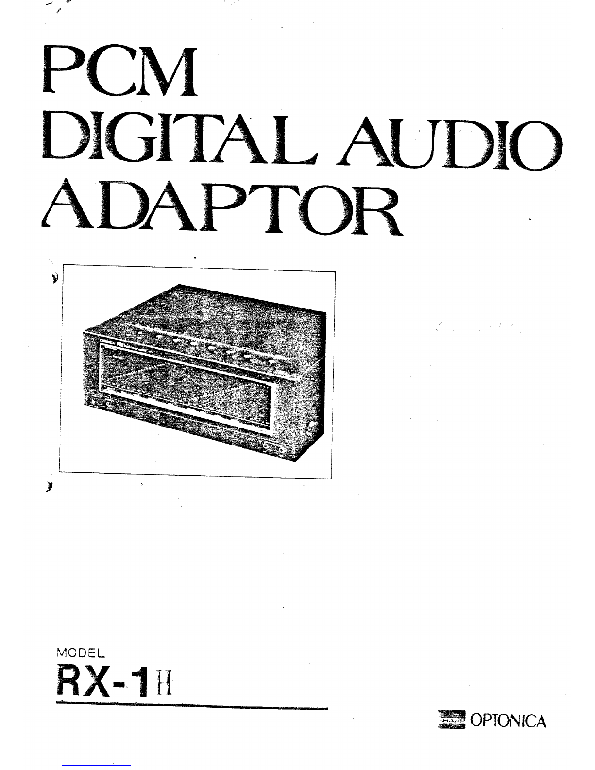
PCMDigitalAudioAdaptor
RX-1KPCM
DIGITALAUDIOADAPTOROPTONICA
Congratulations!YouarenowtheowneroftheOPTONICARX-lHPCMdigitalaudso
adaptor.Tofullyappreciatethebenefitofthisqualityaudioproduct,itisadvisedthat
youreadandthoroughlyunderstandthisoperationalmanualbeforeusing.
FEATURES
1.
MeetsEIAJ(ElectronicsIndustriesAssociationofJapan)standard(825line).
ThisdigitalaudioadaptorismanufacturedtomeettheEIAJstandardarrangedfor
625lineareasandcanbeusedonVHS,Beta,and
U-matic
formats.
2.
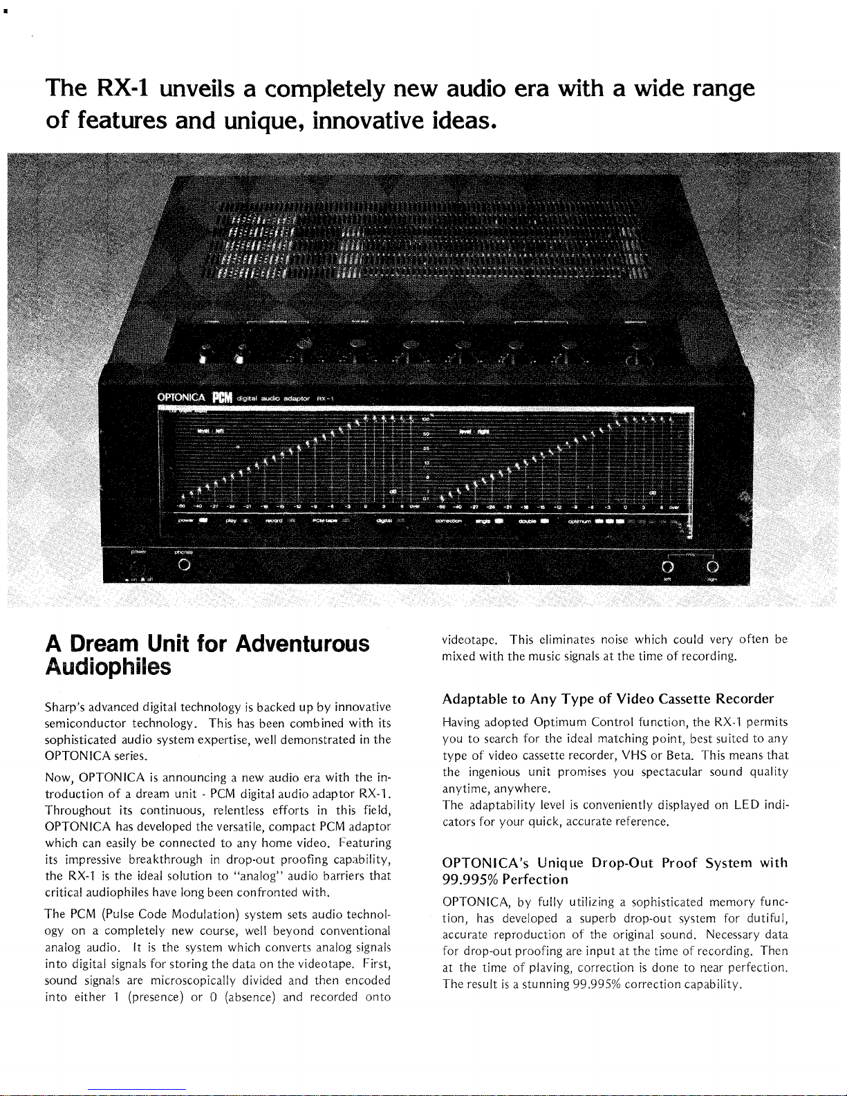
Optimumcontrolfunction
ThiscontrolfunctionmaintainstheRX-iHattheoptimumplaybackperformance
levelwhenusedwithanyvideocassetterecorder.Itcompensatesfora minorper-
formancedeviationinvideocassetterecorders.
3.Equippedwithprofessionaltypeconnectors
BroadcaststandardconnectorssuchascannonconnectorsandPL-259typevideo
conneci®sareusedinadditiontopopularphonoconnectors.
CAUTION
AHintonSettinguptheEquipment
1.
Positionallequipmentforeasyoperation.
2.
Donotoperatetheunitinhumid,dustyareasorexposetheunittoextremeheat.
Atemperatureof30°Corbelowisrecommended.
3.Useanappropriatevoltageregulatorinareaswherevoltagefluctuationisabove
average.
PowerSource
TherecommendedpowersourcefortheunitisAC220V.Donotoperatetheunitexcept
withAC220V.Otherwise,electricalfailuresandotherhazardswillresult,includingfire
andelectricshocks.
Service
Therearenouser-serviceablepartsinside,
authorizeddealerforrepair. Incaseoffailure,taketheunittothenearest
Maintenance
Cleantheunitwithsoftclothandmilddetergent.Neverapplyalcohol,paintthinner,
orotherharmfulchemicals.
Thesedistillateswillsmearthecasingorremovethepaint.
DewProblemona videocassetterecorder
1.
Donotoperatea videocassetterecorderinareaswheremoisturecondensationmight
occur.Moisturecondensationmayoccurinsidetheunitafterheatinga coldroom.
2.
Pleaserefertoanowner'smanualofthevideocassetterecorderforfurtherinfor-
mationondewproblems.


CONTROLSANDFUNCTIONS
1.
Powerswitch
Pushintheswitchto"on"position,andpushitinagainto"off"position.
2.
Headphonejack
Acceptsanyheadphonewith3-ohmimpedance.
3.Powerindicator
Lightsup
when
thepoweris"on".
4.
Playbackindicator
Lightsupwhenmodeswitch
1
2 isin"play"position.
5.Recordindicator
Lightsupwhen*modeswitch12isin"record"position.
8.PCMTapeindicator
ThelampindicatesthePCMTape(similartoa videocassettetape)isbeingplayed
back.
7.Anti-Digitaldubbingindicator
SomePCMTapeshaveanti-dubbingsignalsthatinterferewithdigitaldubbing.The
indicatorshowstheexistenceofsuchsignalsonthetape,anddubbingistherefore
inoperative,
8.frrrorcorrectionsignalindicators
TheseshowthelevelofsignalcorrectionbeingmadeontheprerecordedPCMt.tp<:s.
A"single"lampwilllightupwhensignalcorrectionismadeonce.Iftwo<«*jna!
correctionsarebeingmade,boththe"single"and"double"lamps.v--!ilight. .)
9.Optimumindicators
Thefewertheindicatorsareon,thebettertheplaybackconditionwhenusinga
PCMTape.Whenseveralindicatorsareon,turntheoptimumcontrolknob
clockwiseorcounter-clockwisetoobtainthebestcondition.
10.
LEQlevelindicators
Recordingorplaybacklevelsoneachchannelaremonitored.Levelsettingdiffers
fromtheconventionalmethod.Itisrecommendedthattheaverageinputlevelbeset
around\—9dB;neverletthe"over"indicatorlightup.
11.
MICinputjack
Acceptslowimpedancemicrophonesinrightandleftchannels.
12.
Mode(Record/Play)switch
SelecteitherRecordorPlaymodewiththisswitch.
13.
Errormonitorswitch(Two-waymonitorswitch)
Pushitto"source"positionformonitoringbothrecordingandplaybackper-
formancebyheadphones."Check"positionisformonitoringandcheckingtracking,
optimumcontrollevel,ordropoutswhenusinga videocassetterecorder.
14.
Headphonevolumecontrol
Controlsoutputlevelforheadphones.Variablevolumecontroldoesnotaffect
recordinglevel.
15.
Lineoutputlevelcontrol
Controlsplaybackoutputofthetapedsource.Setthecontrolknobtomaximum
whenusinganamplifier.Levelindicatorsshowthefixedoutput,regardlessof
outputlevelcontroloperation.

16.
Lineinputlevelcontrol
Controlsinputlevelfroma homestereosystemora tapedeck.
17.
MIC
inputlevelcontrol
Controlsinputlevelfrommicrophones.
18.
Optimumcontrol
Maintainsthedigitaladaptoratoptimumplaybackconditionwhenusedw•thany
videocassetterecorder.Itcompensatesa minorperformancedeviationin-/ki^o
cassetterecorders.
19.
Lineinputterminal
(phonojack)
ConnectsRecordoutorLineoutterminalsofanamplifier.Neverusethisterminal
andLineinputterminal(21)(cannontypeconnector)simultaneously1
20.Lineoutput
terminal
(phonojack)
ConnectsTape*playbackorLineinterminalsofanamplifier.
21.
Lineinput
terminal
(cannon
XLR-3-31
type
unbalancedconnector)
Usethisterminalforconnectinga microphonemixerorotherprofessionalaudio
equipment.NeverusethisinputterminalandLineinputterminal(19) (phonojack)
simultaneously!
Thenumberthreepinisa hotwire.
22.Lineoutput
terminal
(cannon
XLR-3-32
type
unbalancedconnector)
UsethisterminalforconnectingLineoutputofprofessionaltypeamplifiers.
23.
Digital
input/output
terminal
UsethisterminalforconnectinganotherRX-lHdigitaladaptor'sinput,'outout
terminalwhendigitaldubbingisperformedbyusingtwoRX-llijigitaijttaptorsand
twovideocassetterecorders.
24.Videoinput
terminal
Usethisterminalforconnectingthevideooutputterminalofa videocassette
recorder.Neveruse
thisvideoinput
terminalandPL-259typevideoinputterminal
(26)atthesametime!
25.
Video
output
terminal
Usethisterminalforconnectingthevideoinputterminalofa videocassetterecorder.
NeverusethisterminalandthePL-259typevideooutputterminal(27)simul-
taneously!
26.Videoinput
terminal(PL-259
typeconnector)
UsethisterminalforconnectingthePL-259
type
videooutputterminalofa video
cassetterecorder.Neverusethisterminalandanadditionalvideoinputterminal
(24)simultaneously!
27.
Video
output
terminal(PL-259
typeconnector)
UsethisterminalforconnectingthePL-259typevideoinputterminalofa video
cassetterecorder.Neverusethisterminalandanadditionalvideooutputterminal
(25)simultaneously!
28.
Dubbing
output
terminal
Usethisterminalwhendubbingisperformedbyusingthisdigitaladaptorjndtwo
videocassetterecorders.Connectittothevideoinputterminaloftherecording
videocassetterecorder.
29.
External
syncoutput
terminal
(phonojack)
Connecttotheexternalsyncinputterminalofa videocassetterecorder.
30.
Externalsyncoutputterminal(PL-259type)
ConnecttothePL259typeexternalsyncinputterminalofa videocassetterecorder.
4-

PLAYBACK
Refer
tothe
owner'smanual
forthe
operation
ofa
videocassetterecorder.
v
1.
Makeconnectionsasillustrated:seediagram[2]—[3J-
2.
Push
"on"the
powerswitch
{1).
3.Switch
the
modeselector
to
"play"position.
4.
Load
a PCM
tapeinto
a video
cassetterecorder.
5.
Setthe
videocassetterecorder'strackingcontrolknob
to
autoposition,
ortothe
centerposition
if
manually
set.
6.Connect
a
headphone
tothe
headphonejack
(2).
7.Playback
the
videocassetterecorder
andsetthe
errormonitorswitch(two-way
monitorswitch)
to
"check"position.
8.Adjustoptimumcontrol
by
monitoringoptimumindicators.
9.Obtainmaximumtrackingcontrol
by
listening
tothe
checkingsignals.
10.
Now,the
tape
Canbe
playedbackanytime.
•Duringoptimumcontrol
or
trackingcontrol,turndown
the
amplifiervolume
andset
themonitorswitch
tothe
"monitor"position.
•Once
the
initialoptimumcontrol
and
trackingcontrol
is
adjusted,there
isno
further
adjustment
necesHryas
long
asthe
videocassetterecorder
is
used.
•Always
usea
reliablevideocassetterecorder
in
excellentworkingcondition
in
order
toobtainmaximumperformancefrom
the
digitaladaptor.Always
keepthe
video
headsclean.
•Whenusing
a
prerecorded
PCM
tape,makesure
it
complieswith
thePCM
recording
standard.
Error
Monitor
Switch
(Two-way
Monitor
Switch)
SourcePosition
•Recording
and
playbackconditions
are
monitored
by
headphoneswhen
the
switch
is
in"source"position.
•When
the
switch
isin
"check"position,
the
headphonespick
upthe
intermittent
signalsound
to
indicatewhether
the
optimumcontrol
or
trackingcontrol
is
properly
set.
The
better
the
condition,
the
lessaudible
the
signalbecomes.
Usually,
setthe
trackingcontrol
to
"auto"position.When
the
signalsoundbecomes
quick
and
clearlyaudible,
the
playbackcondition
ispoor.
Proceed
tosetthe
tracking
controlmanually
to
obtain
the
optimumplaybackcondition.
For
manualsettings,
follow
the
instructionsbelow:
t.Listencarefully
tothe
signalsound.Count
a
number
of
signalsaudiblewithin
a
period
of
fiveseconds.Turning
ofa
trackingcontrolknobwilleitherincrease
or
decrease
signalinterval.
Setthe
knobwhere
the
leastamount
of
signal
is
audibiewithin
a
period
of
fiveseconds.Repeatthisseveraltimes
to
obtainmaximumtrackingcontrol.
When
the
trackingcontrolknob
is
turned,tracking
is
momentarilydisturbed.When
makingan
adjustment,wait
untilthe
tracking
is
stabilized
andno
continuoussignal
sound
isheard.
•
The
signalsound
is
onlyreproduced
bythe
headphoneterminal
(2)andit
won't
be
reproducedthrough
the
speakers.
•Everytime
a
videocassetterecorder/videocassettetape
is
changed,
be
sure
to
make
trackingcontrol
and
optimumcontroladjustments.
•Whenrecording,pushback
the
switch
tothe
"source"position.

OPTIMUM
CONTROL
Thiscontrolmaintainstheoptimumperformancefromthedigitaladaptorevenwhenthe
videocassetterecorderdeviatesfromnormalperformancefigures.
1.
First,setthisknobtothenotched"middle"position.
2.
Optimumindicatorswilllightupwhena PCMTapeisplayedback.Lessthan:-vo
indicatorswilllightupiftheplaybackconditionisfavourable,w^enrhe;
conditionispoor,severalindicatorswilllightuptoshowthattheopt-mumcor:re;
requiresreadjustment.Adjusttheknobsothatthefewesttampsw } besi!-i-vr/itrc
•Readjusttheknobeachtimea videocassetterecorder/cassettetapeischanged.
•Sincetheperformancecharacteristicsofeachvideocassetterecordermayarv
maybecaseswhentwotothreeindicatorslightupeveniftheplaysackcord.:cr. 3
verygood.Alloptimumindicatorsmaylightuprightaftera videocassette'ecjrc:-:'s
hookedtothedigitaladaptor.Thisdoesnotindicatethemachineinmalfuncf
~--r-.
-3.
JustplaybacktnePCMTape,andwaituntilthePCMTapeindicatorisonc^fcre
makinganyadjustment.
RECORDING
Refertotheowner'smanualfortheoperationofa videocassetterecorder.
1.
Makeconnectionsasillustrated:seediagram
[Tj-[2].
2.
Push"on"thepowerswitch(1).
3.Switchmodeselector(12)to"record"position.
4.
AdjusttoproperrecordinglevelbyturningtheLineinputcontrol(16)knoborMIC
inputcontrol(17)knob.Setthelevelindicator(10)forvisualcheckingofinputlevel.
5.Loadthevideotape.Clearthetapecountertozeroonthevideocassetterecorder,
Presstherecordbutton.
•Sinceittakesseveralsecondsforthevideocassetterecordertobestabilized,.73<t
severalsecondsbeforestartingtorecord.
-Whenthemicrophoneisnotused,turntheMICinputcontrolknobto"0"position.
•Alwaysusereliablevideocassetterecordersinanexcellentworkingconditionsto
obtainmaximumrecordingperformancefromthedigitaladaptor.Alwayskeepthe
videoheadsclean.
•Whenrecording,PCMTape(optionallyavailable)isrecommended.
•Whenrecordingiscompleted,letthevideocassetterecorderrunforseveralseconds
beforedisengagingtherecordbutton.
•Whenrecordingrightafterthepreviouslyrecordedprogrammes,letthevideocassette
recorderruninplaybackmodeforseveralsecondsbeforepressingtherecordbutton.
ProperRecordingLevel
Settheaveragerecordinglevelatabout—9d3.
1.
CheckthelevelindicatorsandadjusttheLineinputcontrol(18)orMICinputcontrol
(17)
tosettheaveragerecordinglevelascloseaspossibleto-9d3for3
normalrecording.
2.
Settingoftheaveragerecordinglevelatmorethan—9dBproducesgoodPCMrecord-
ingresults.ButNEVERallowthe"Over"levelindicatortolightup!
3.Varytheaveragerecordinglevelbeloworover—9dBdependingonthetypeofrecord
ing.
•Setpeakrecordinglevelbelowthe"OVER"level,butdonotsetittoolow;otherwise
a
poorS/Nratiowillresult.

DUBBING
Therearebasicallythreemethods-ofdubbingusingthisdigitalaudioadaptor.
DubbingCanBePerformedUsingTVSignals
1.
Push"on"thepowerswitch.
2.
Switchthemodeselectortoplayposition?
3.Paybackthevideocassetterecorder,(refertoPLAYBACKsection)
4.
Settorecordmodeonthevideocassetterecorder,(refertoPLAYBACKsection)
5.Dubbingisnowinprocess.
•AdjustingPlaybackoutputcontrol(15),Lineinputcontrol(16),orMICinputcontrol
(17)doesnotaffectreceordinglevel.
Analog
Dubbing
1.
Pushonthepowerswitch(1).
2Switchthenlodeselector(12)to"play"positionontheplaybackdigital
audioadaptor.
3.Switchthemodeselector(12)to"record"positionontherecordingdigitalaudio
adaptor.
4.
Playbackthesource(playback)videocassetterecorder,(refertoPLAYBACKsection)
5Settherecordmodeontherecordingvideocassetterecorder,(refertoPLAYBACK
section)
6.Nowdubbingisinprocess.
DigitalDubbing
1.
Refertodiagram16]forconnections.
2.
Operationprocedureisidenticaltotheanalogdubbing.
*TheremaybecertaincaseswhenusingtheTVsignalwillnotproducegooddubbing
results.Thisisbecausethereareminorperformancedeviationsamongvideocassette
recordersandvideocassettetapes.Ifthisisthecase,performanalogordigital
dubbingasexplainedearlier.
7

or
live
recordings
Diagram
1
s

Recordingfroma recordalbum.FM
broadcast
or
tape
recorder,
andplayback::Diagram2

Line
input
Microphone
inixer
Amplifier
VI.
Dh;0OUT
Connectingwith
professional
equipment:Diagram3;
Line
input
Cannon
conneetorcable
Lino
out
pu
t
Line
output
Video
input
Video
output
RX-IH
.Power
souroe
PQ.ver
;jourco
VI
DhlO IN
VTR
VC-6300
Video
input
Video
output
Coaxial
cablesprovided

TV
signaldubbingconnection:- Diagram4

Analog
dubbingconnection:
Diagram
5"

Digital
dubbingconnection:
Diagram
_6j

SPECIFICATIONS
*
Specificationsaresubjecttochangewithoutnotice.
*
Themanufacturerreservestherighttovaryspecifications,design,orusealternative
materialsasmaybedeemednecessaryordesirableatanytime,anysuchchangeor
variationbeingofa kindasnottoreducethequality,performanceorappearance.
Powersource:AC220V,50Hz
Powerconsumption:38W
Dimensions:430(W)x 141(H)x 360(D)
Weight:15,5kg
Inputterminals:
MICinputterminal:Lowimpedancemicrophone;
Minimuminputlevel,3mV(—48dBm)ork>ss.
Lineinputterminal:Phoneconnector/cannonconnectorXLR-3-31
unbalanced;
Minimuminputlevel,iGOmV
'(—18dBm)orless;Inputimpedance,47kohms.
Videoinputterminal:Phonoconnector/PL-259typeconnector,
Inputlevel,1.010.2Vp-p{75ohmstermination!.
Outputterminals:
Dubbingoutput
terminal:
Phonoconnector;Outputlevel,
1.010.2
Vp-p
*
(75ohmstermination);Outputimpedance,
75ohms.
Lineoutputterminal:Phoneconnector/cannonXLR3-32connector,
unbalanced;
Outputlevel,5G0mV(-4dSm)or
moreforphonoconnectors,1.23V
(t-4dBm}
or
moreforcannonconnectors;600-ohmloaded
impedance;Matching
loaded
impedance,10kohms
or
moreforphonoconnector,600
ohms
ormore
forcannonconnectors.
Videooutputterminal:Phonoconnector/PL-259connector.Outputlevel,*
1.0t 0.2Vp-p(75ohmstermination};Output
impedance,75ohms.
Externalsyncoutput
terminal:
Phonoconnector/PL-259connectors;TTLlevel.
Digitalinput/outputterminal:
D-type
subconnector;TTLlevel.
AuxiliaryVideoCassetterecorder:SharpVC-6300{VHSformat);Setaformat;
U-matic
format.
•
Frequencyresponse:2 — 20,000Hz
Dynamicrange:90dB
Harmonicdistortion:0.03%
(1kHz)
Wow& flutter;Belowmeasurablevalue.
Levelvariation:Belowmeasurablevalue.
Crosstalk:Morethan60dB.
Errorcorrectioncapability:99.995%
Standard:
ElAJstandard(525line)
Recordingformat:PCMrecordingin625linestandardTVsignals.
Transmissionchannels:Twochannels.
Samplingfrequency:44.1kHz
Numberofquantizingbit:14-bit
Data
transmissionrate:2.525Mops-
Accessories:Phonotypeconnectingcable;Phonotype/PL-259
Typecoaxialcablex 2 (75ohms};Owner'smanual.
Table of contents
Other Sharp Adapter manuals
Popular Adapter manuals by other brands

Sony
Sony PEGA-AC10 Operating Instructions (primary... operating instructions

Enterasys
Enterasys RBTSA-AA user guide

Toro
Toro 30104 installation instructions

National Instruments
National Instruments NI 9949 RJ-50 user guide

Garmin
Garmin GST 10, Water Speed and Temperature Adapter Installation and... Installation and configuration

SIIG
SIIG JJ-P20511-S3 Quick installation guide