Standard Source Operating Range Accuracy
Required
Recommended
Equipment
K-Type Thermocouple
Simulator or Calibrator –50 ~ 1000 °C
–58 ~ 1832 °F ≤ ±0.1% + 1 °C CL-300-1000C from OMEGA or Fluke-5520A
Multimeter DC 1000.0 mV ≤ ±0.1% Keysight-U1251A, U1252A or Keysight-34405A
Ice Point Reference
Chamber –5 ~ 38 °C ≤ ±0.1% + 0.5 °C TRCIII from OMEGA or Fluke -5520A
Adjustment Procedures
The following procedures are to be performed in sequence after another to ensure a correct calibration se-
quence.
Celsius Temperature Offset Adjustment
1. Set the operating range of the digital multimeter to DC 1000.0 mV.
2. Set the reference standard to 0 ºC.
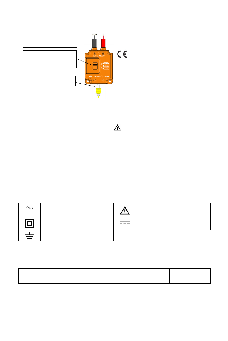
3. Switch the adapter’s slider to the ºC position.
4. Connect the K-type miniature connector from the reference standard into the input of U1586B
adapter.
5. Plug in the banana ends of the adapter’s output to the V and COM input terminals of the digital
multimeter.
6. Wait for at least 30 seconds for the signal conversion from ºC to Volts to stabilize at the multimeter
display.
7. Observe that the multimeter reading should display a voltage of 0.0 mV ± 0.2 mV.
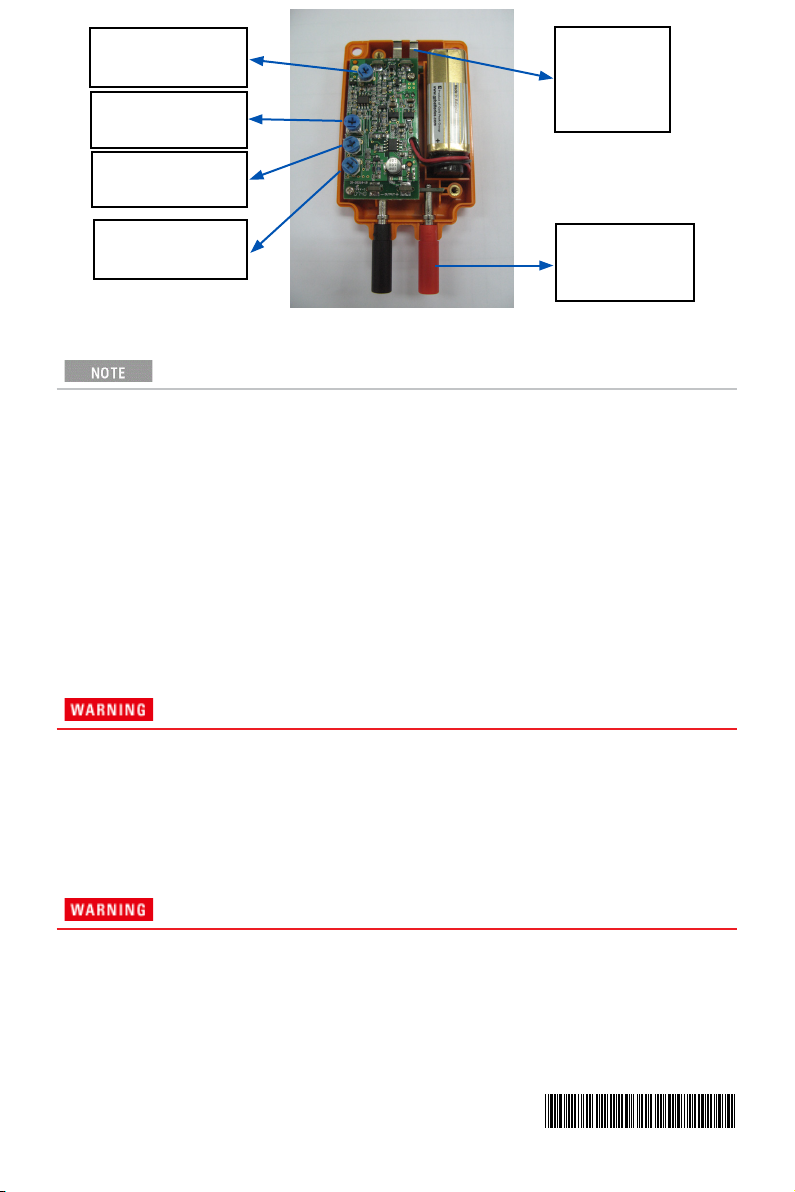
8. If the multimeter reading display does not meet the required voltage, unscrew 2 Phillips head
screws at the back panel of the adapter using a Phillips tip screwdriver and remove the rear cover.
9. Look for VR3 (refer to Figure 1 for the location of VR3 in the adjustment diagram) and carefully
adjust the variable resistor using a small Phillips tip screwdriver until the display of the multimeter
meets the required reading of 0.0 mV ± 0.2 mV.
10. After performing the adjustment of VR3, remember to replace the rear cover of the adapter or
proceed to the next calibration process.
Celsius Temperature Gain Adjustment
1. Set the operating range of the digital multimeter to DC 1000.0 mV.
2. Set the reference standard to 300 ºC.
3. Switch the adapter’s slider to the ºC position.
4. Connect the K-type miniature connector from the reference standard into the input of U1586B
adapter.
5. Plug in the banana ends of the adapter’s output to the V and COM input terminals of the digital
multimeter.
6. Wait for at least 30 seconds for the signal conversion from ºC to Volts to stabilize at the multimeter
display.
7. Observe that the multimeter reading should display a voltage of 300.0 mV ± 0.2 mV.
8. If the multimeter reading display does not meet the required voltage, unscrew 2 Phillips head
screws at the back panel of the adapter using a Phillips tip screwdriver and remove the rear cover.
9. Look for VR1 (refer to Figure 1 for the location of VR1 in the adjustment diagram) and carefully
adjust the variable resistor using a small Phillips tip screwdriver until the display of the multimeter
meets the required reading of 300.0 mV ± 0.2 mV.
10. After performing the adjustment of VR1, remember to replace the rear cover of the adapter or
proceed to the next calibration process.
Fahrenheit Temperature Offset Adjustment
1. Set the operating range of the digital multimeter to DC 1000.0 mV.
2. Set the reference standard to 32 ºF.
3. Switch the adapter’s slider to the ºF position.
4. Connect the K-type miniature connector from the reference standard into the input of U1586B
adapter.
5. Plug in the banana ends of the adapter’s output to the V and COM input terminals of the digital
multimeter.
6. Wait for at least 30 seconds for the signal conversion from ºC to Volts to stabilize at the multimeter
display.
7. Observe that the multimeter reading should display a voltage of 32.0 mV ± 0.2 mV.
8. If the multimeter reading display does not meet the required voltage, unscrew 2 Phillips head
screws at the back panel of the adapter using a Phillips tip screwdriver and remove the rear cover.
9. Look for VR4 (refer to Figure 1 for the location of VR4 in the adjustment diagram) and carefully
adjust the variable resistor using a small Phillips tip screwdriver until the display of the multimeter
meets the required reading of 32.0 mV ± 0.2 mV.
10. After performing the adjustment of VR4, remember to replace the rear cover of the adapter or
proceed to the next calibration process.