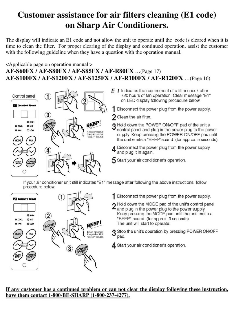
SW1
DSW1
PUMP DOWN
CURRENT
SELECT
LED1A
LED1B
LED1C
OFF
1
2
ON
Lo Hi
N L
N 1 2
N 1 2
N 1 2
Pump down is adopted in the case of unit removal for re-installation, abandonment, repair etc.
Pump down is to collect the refrigerant into the outdoor unit.
PROCEDURE USING GAUGE MANIFOLD (Recommended procedure)
(1) Connect the gauge manifold hose to the service port of the stop valve(gas side).
(2) To start pump down, press the PUMP DOWN button(SW1) for 5 seconds or more.
The OPERATION lamp on the indoor unit will flash and three BEEP will be emitted.
(3) After 5-10 minutes, fully close the stop valve (liquid side).
(4) Close the stop valve (gas side) when the compound gauge reading becomes almost 0 MPa(0 cmHg).
(5) To stop the pump down, press the PUMP DOWN button(SW1) for 5 seconds or more.
(6) Disconnect the gauge manifold hose from the service port.
PROCEDURE WITHOUT USING GAUGE MANIFOLD
(1) To start pump down, press the PUMP DOWN button(SW1) for 5 seconds or more.
The OPERATION lamp on the indoor unit will flash and three BEEP will be emitted.
(2) After 5-10 minutes, fully close the stop valve (liquid side) .
(3) After 2-3 minutes, close the stop valve (gas side) fully.
(4) To stop the pump down, press the PUMP DOWN button(SW1) for 5 seconds or more.
Caution:
•Make sure that the compressor is turned off before removing the refrigerant pipes. Otherwise, it will
cause burst and injury.
•Do not perform PUMP DOWN when refrigerant is leaking or there is no refrigerant in the refrigerant cycle.
Otherwise, it will cause burst and injury.
Note:
•Wait more than 90 seconds after finishing pump down, and turn off the circuit breaker off.
Lo Hi
Use a copper cable.
Use a cable which is not lighter than polychloroprene
sheathed flexible cord (code designation 60245 IEC 57).
Cross-section area
Power supply cable 2.0 mm2or more
Connecting cable 1.0 mm2or more
(1) Process the end of the cables for the outdoor unit.
• For power supply cable, securely clamp a round
terminal to each end of the stripped cable.
(2) Remove the cable holder and connect the cables.
(3) Fix the cable sheath with the cable holder and the
screw.
(4) Double-check that the cable is securely in place.
(5) Fix the cables with the cable fixing band.
Caution:
•Be very careful not to confuse the terminal connec-
tions. Wrong cabling may damage the internal control
circuit.
•Be sure to connect the cable to match the markings
on the outdoor unit’s terminal board and those of the
indoor unit.
•Be sure to put the cable leads deep into the terminal
board and tighten up the screws. Poor contact can
cause overheating or fire, or malfunction.
Test run with the indoor unit
See the installation manual accompanying indoor unit.
UNIT B
Power supply cable
Hexagon wrench
Gauge manifold
Compound
gauge
UNIT A
Perform air removal using a vacuum pump.
Use a vacuum pump, gauge manifold and hoses exclusively for R410A.
(1) Remove both valve shaft caps of the stop valves.
(2) Remove the service port cap of the stop valve (gas side).
(3) Connect the gauge manifold hose to the service port and the vacuum pump.
Be sure that the hose end to be connected to the service port has a valve
core pusher.
(4) Open the gauge manifold valve and operate the vacuum pump for 10-15
minutes.
Make sure the compound gauge reads -0.1 MPa(-76 cmHg).
(5) Close the gauge manifold valve.
(6) Turn off the vacuum pump.
Leave as it for 1-2 minutes and make sure the needle of the compound
gauge does not go back.
(7) Open the stop valve (liquid side) 90° counterclockwise by turning the hexa-
gon wrench. Close it after 5 second, and check for gas leakage.*
(8) Disconnect the gauge manifold hose from the service port.
(9) Fully open the stop valve (liquid side) with hexagon wrench.
Turn all the way up to contact.
(10)
Fully open the stop valve (gas side) with hexagon wrench. Turn all the way
up to contact.
(11)
Firmly tighten the service port cap and both valve shaft caps with a torque
wrench at the specified tightening torque.
* Check the pipe connections for gas leak using a leakage detector or soapy
water. Regarding leakage detector, use high-sensitivity type designed specially
for R410A.
Valve shaft cap tightening torque
Torque
Liquid side 24±3 N·m (2.4±0.3 kgf·m)
Gas side 31±3 N·m (3.1±0.3 kgf·m)
Miswiring of connecting cable will be self-corrected by the wire check operation.
(1) Turn the circuit breaker on.
(2) Check that all LED(LED1A, LED1B, LED1C) on the display board are flashing simultaneously.
If one or more of the LED is/are kept lit, check for mismatching terminal markings(N, 1, 2, ) and
correct them.
(3) To start the wire check, press the WIRE CHECK button(SW2) for 5 seconds or more.
The red operation lamp on the indoor unit will flash, and three BEEP will be emitted.
All LED will flash rapidly.
(4) When wire check is completed normally, all LED will flash simultaneously and the operation
will stop. (Wire check time: 10 - 15 minutes)
When self-correction can not done, all LED will indicate triple flash for eight times and the
operation will stop. Check and correct following points.
• Check all pipings are connected.
• Check the stop valves are open.
After correction, repeat the wire check again. If error is still detected, or other types of LED
signal should be indicated, please contact a service technician. (Refer to wiring diagram at-
tached inside the outdoor unit for self diagnosis signal.)
Note:
• For two indoor units, the LED for the indoor unit which is not connected will keep lighting.
• Wire check may not be performed when the outdoor temperature is below 5°C.
Valve shaft cap
OPEN
Stop valve
(gas side)
Stop valve
(liquid side)
Hose
Service port
Stop valve
(gas side)
Stop valve
(liquid side)
Vacuum pump
Service port
Power supply cable
Connecting cable
SW1
DSW1
SW2
PUMP DOWN
CURRENT
SELECT
WIRE CHECK
LED1A
LED1B
LED1C
OFF
1
2
ON
70mm
85mm
8mm
75mm
Earth wire Earth wire
PUMP DOWN
WIRE CHECK button (SW2)
PUMP DOWN button (SW1)
Connecting cable
•Fit a disconnect switch, having a contact separation of at
least 3mm in all poles, to the electricity power line.
Prepare a dedicated power supply circuit. For
the connections, see below.
Supply power 230 V, single-phase, 50 Hz
Circuit breaker 20 A
Service port cap tightening torque
Torque
11±1 N·m (1.1±0.1 kgf·m)
Slide the CURRENT SELECT switch(DSW1) to set the desired limit current.
DSW1
LIMIT
CURRENT
8.5 A
(Factory setting) Free 11 A 8.5 A
OFF
1
2
ON OFF
1
2
ON OFF
1
2
ON
4mm
Cable fixing band 2
OFF
1
2
ON
LED1A
SW1
DSW1
PUMP DOWN
CURRENT
SELECT
LED1B
LED1C
OFF
1
2
ON
CURRENT SELECT
switch (DSW1)
3
AIR REMOVAL
4
CONNECTING THE CABLE TO THE OUTDOOR UNIT
5
POWER CABLING
6
WIRE CHECK
7
LIMIT CURRENT SETTING
8
TEST RUN
Cable holder
9 ITEMS TO CHECK
Is the specified power supply voltage used?
Is the connecting cable fixed to terminal board firmly?
Is the earth wire connected properly arranged?
Is the drainage properly?
Is there any gas leakage at the pipe connection?
EXPLANATION TO CUSTOMER
• Explain to the customer how to use and maintain the system, referring to the
operation manual.
•Ask the customer to carefully read the operation manual.
• When the system has been set up, hand the installation manual to the customer.
TINS-B508JBRZ
Test run with the outdoor unit
(1) To start test run, press the PUMP DOWN button(SW1) for 5 seconds or more.
The OPERATION lamp on the indoor unit will flash and three BEEP will be emitted.
All indoor units operate in the cooling test run mode.
(2) Make sure the system runs well.
To stop the operation, press the PUMP DOWN button(SW1) for 5 seconds or more.
SW1
SW2
PUMP DOWN
WIRE CHECK
LED1C
PUMP DOWN button (SW1)
UNIT C
Gauge manifold
Compound
gauge
Service port
A3AUX3M24RV.indd 2
• All LED (LED1A, LED1B, LED1C) on the display board will flash by turns.
• All LED (LED1A, LED1B, LED1C) on the display board will flash by turns.
•
•
•
