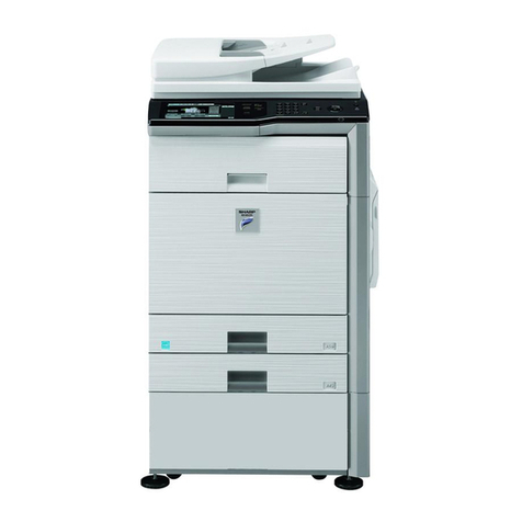
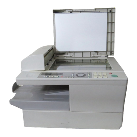
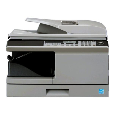
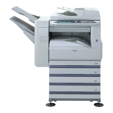
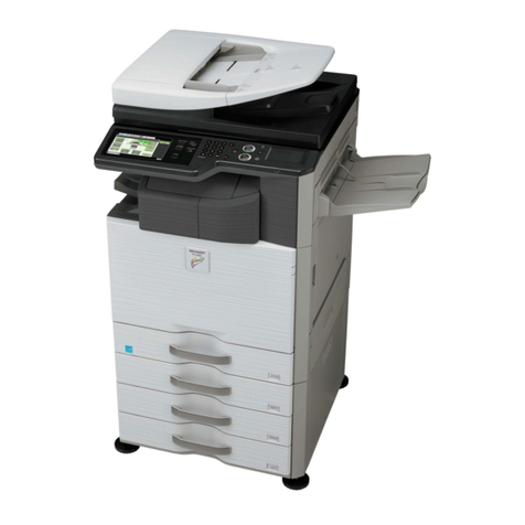
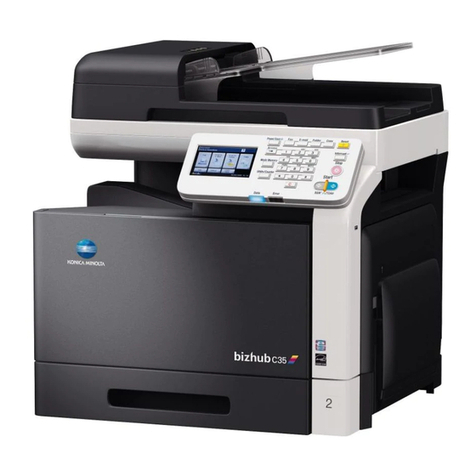
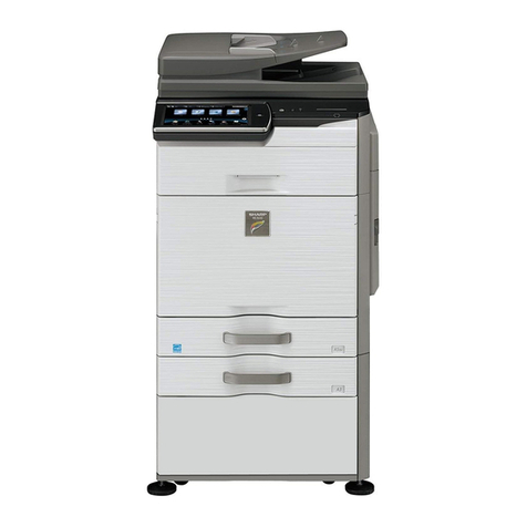
Sharp MX-M182 User manual

INSTALLATION MANUAL
Parts marked with “ “ are important for maintaining the safety of the set.
Be sure to replace these parts with specified ones for maintaining the safety and performance of the set.
SHARP CORPORATION This document has been published to be used
for after sales service only.
The contents are subject to change without notice.
MX-M232D
MX-M202D
MX-M182D
MX-M182
(With optional SPF/RSPF installed)
DIGITAL MULTIFUNCTIONAL
SYSTEM
MX-M182
MX-M182D
MX-M202D
MX-M232D
CODE : 00ZMXM182/I2E
MODEL
[ 1 ] GENERAL. . . . . . . . . . . . . . . . . . . . . . . . . . . . . . . . . . . . . . . . . . 1-1
[ 2 ] CONFIGURATION . . . . . . . . . . . . . . . . . . . . . . . . . . . . . . . . . . . 2-1
[ 3 ] MX-M232D/MX-M202D/MX-M182D/MX-M182. . . . . . . . . . . . . . 3-1
[ 4 ] AR-SP10/AR-RP10. . . . . . . . . . . . . . . . . . . . . . . . . . . . . . . . . . . 4-1
[ 5 ] AR-D36/AR-D37 . . . . . . . . . . . . . . . . . . . . . . . . . . . . . . . . . . . . . 5-1
[ 6 ] MX-FX13/MX-XB17. . . . . . . . . . . . . . . . . . . . . . . . . . . . . . . . . . . 6-1
[ 7 ] MX-NB12. . . . . . . . . . . . . . . . . . . . . . . . . . . . . . . . . . . . . . . . . . . 7-1
[ 8 ] MX-TR10. . . . . . . . . . . . . . . . . . . . . . . . . . . . . . . . . . . . . . . . . . . 8-1
[ 9 ] MX-EB14. . . . . . . . . . . . . . . . . . . . . . . . . . . . . . . . . . . . . . . . . . . 9-1
[10] MX-PK10 PS3 EXPANSION KIT. . . . . . . . . . . . . . . . . . . . . . . . 10-1
[11] CHANGING THE COPY PAPER SIZE IN THE TRAY. . . . . . . . 11-1
[12] ADJUSTMENTS . . . . . . . . . . . . . . . . . . . . . . . . . . . . . . . . . . . . 12-1
CONTENTS

Disconnect the AC cord before servicing the unit. LASER WAVE - LENGTH : 785 15mm
Pulse times : 10.34Ǵsr0.1Ǵs/7mm㧧MX-M182,MX-M182D,MX-M202D
8.665Ǵsr0.1Ǵs/7mm㧧MX-M232D
Out put power : Max.0.3mW

MX-M232D (GENERAL) 1 - 1
[1] GENERAL
1. Note for servicing
Pictogram
The label ( ) in the fusing area of the machine indicates the
following:
: Caution, risk of danger
: Caution, hot surface
A. Warning for servicing
•The fusing area is hot. Exercise care in this area when removing misfed
paper.
•Do not disassemble the laser unit. Do not insert a reflective material
such as a screwdriver in the laser beam path.
It may damage eyes by reflection of laser beams.
B. Cautions for servicing
•Do not switch the machine rapidly on and off. After turning the machine
off, wait 10 to 15 seconds before turning it back on.
•Machine power must be turned off before installing any supplies.
•Place the machine on a firm, level surface.
•Do not install the machine in a humid or dusty location.
•When the machine is not used for a long time, for example, during
prolonged holidays, turn the power switch off and remove the power
cord from the outlet.
•When moving the machine, be sure to turn the power switch off and
remove the power cord from the outlet.
•Do not cover the machine with a dust cover, cloth or plastic film while
the power is on. Doing so may prevent heat dissipation, damaging the
machine.
•Use of controls or adjustments or performance of procedures other than
those specified herein may result in hazardous laser radiation
exposure.
•The socket-outlet shall be installed near the machine and shall be easily
accessible.
C. Note for installation place
Improper installation may damage the machine. Please note the
following during initial installation and whenever the machine is moved.
Caution : If the machine is moved from a cool place to a warm place,
condensation may form inside the machine. Operation in this
condition will cause poor copy quality and malfunctions. Leave
the machine at room temperature for at least 2 hours before
use.
Do not install your machine in areas that are:
•damp, humid, or very dusty
•poorly ventilated
•exposed to direct sunlight
•subject to extreme temperature or humidity changes, e.g., near an air
conditioner or heater.
The machine should be installed near an accessible power outlet for
easy connection and disconnection.
Be sure to connect the power cord only to a power outlet that meets the
specified voltage and current requirements. Also make certain the outlet
is properly grounded.
Note : Connect the machine to a power outlet which is not used for other
electric appliances. If a lighting fixture is connected to the same
outlet, the light may flicker.
Be sure to allow the required space around the machine for servicing
and proper ventilation.
20 cm
(8
"
)
20 cm
(8
"
)
20 cm (8
"
)
MX-M232D (GENERAL) 1 - 2
D. Note for handling PWB and electronic parts
When handling the PWB and the electronic parts, be sure to observe the
following precautions in order to prevent against damage by static
electricity.
1) When in transit or storing, put the parts in an anti-static bag or an anti-
static case and do not touch them with bare hands.
2) When and after removing the parts from an anti-static bag (case), use
an earth band as shown below:
• Put an earth band to your arm, and connect it to the machine.
3) When repairing or replacing an electronic part, perform the procedure
on an anti-static mat.

MX-M232D (CONFIGURATION) 2 - 1
[2] CONFIGURATION
1. System Configurations
AR-D36 AR-D37
AR-SP10
MX-M182MX-M232D MX-M182D
MX-M202D
AR-VR7
(MX-M182 is standard)
MX-NB12
AR-RP10
(MX-M182D/M202D/
M232D only)
MX-FX13
MX-EB14
MX-XB17
MX-TR10
MX-USX1
Sharpdesk 1 license kit
MX-PK10
PS3 EXPANSION KIT
MX-USX5
Sharpdesk 5 license kit
MX-US10
Sharpdesk 10 license kit
MX-US50
Sharpdesk 50 license kit
MX-USA0
Sharpdesk 100 license kit

MX-M232D (CONFIGURATION) 2 - 2
STD: Standard
O
: Option installation enable
X
: Option installation disable
*1 Standard for U.S.A
*2 Not available for U.S.A
*3 MX-NB12 or MX-XB17 is required.
*4 MX-NB12 is required.
Model
Option MX-M182 MX-M182D/202D/232D
AR-RP10 Reversing single pass feeder (RSPF)
XO *1
AR-SP10 Single pass feeder (SPF)
OO *2
AR-D36 250-sheet paper feed unit
O O
AR-D37 2x250-sheet paper feed unit
O O
AR-VR7 DOCUMENT COVER STD
O *2
MX-NB12 NETWORK EXPANSION KIT
O O
MX-FX13 FACSIMILE EXPANSION KIT
O *3 O *3
MX-XB17 FACSIMILE MOUNTING KIT
O O
MX-TR10 JOB SEPARATOR
O O
MX-EB14 EXPANSION MEMORY BOARD
O O
MX-PK10 PS3 EXPANSION KIT
O*4 O*4
MX-USX1 SHARPDESK 1 LICENSE KIT
O O
MX-USX5 SHARPDESK 5 LICENSE KIT
O O
MX-US10 SHARPDESK 10 LICENSE KIT
O O
MX-US50 SHARPDESK 50 LICENSE KIT
O O
MX-USA0 SHARPDESK 100 LICENSE KIT
O O

MX-M232D (MX-M232D/M202D/M182D/M182) 3 - 1
[3] MX-M232D/M202D/M182D/M182
1. Installing conditions
A.The machine installation
Do not install your the machine in areas that are:
•damp, humid, or very dusty
•exposed to direct sunlight
•poorly ventilated
•subject to extreme temperature or humidity changes, e.g., near an air
conditioner or heater.
•Be sure to allow the required space around the machine for servicing
and proper ventilation.
B.Power source
•Use an exclusive to dedicated power outlet. If the power plug of this
machine is inserted into a power outlet commonly used with other
illumination units, flickers of the lamp may be result. Use a power outlet
which is not used commonly with any illumination units.
•Avoid complex wiring.
C.Grounding wire connection.
•To avoid danger, the power outlet must be grounded. If no grounding
wire is connected and a leakage occurs, a fire or an electric shock may
be result.
2. Removal of protective material and fixing
screw
1) Remove all tapes and protective material.
•Remove all tapes, then open the document cover and remove the
protective material of sheet shape
2) Remove the fixing screw.
•Use a coin to remove the fixing screw.
•The fixing screw is required when transporting the machine. Keep it in
the tray. (Refer to the later description.)
3.Installing procedure
A.Developer cartridge installation
1) Open the bypass tray, and open the side cover.
2) Open the front cover.
•Hold the both sides and pull down to open.
3) Loosen the screw and remove the developer cartridge.
4) Remove the developer tank from the developer cartridge.
5) While rotating the MG roller in the arrow direction, supply the
developer into the developer tank evenly so as not to overflow.
* Shake the developer bag enough before opening it.
MG roller

MX-M232D (MX-M232D/M202D/M182D/M182) 3 - 2
6) Check that two hooks of the developer unit is hooked on the toner
cartridge guide, and secure the toner cartridge guide to the
developing unit.
* Check that the DV seal is free from the developer. If developer is
attached to the DV seal, clean it.
* After supplying developer, do not tilt or shake the developer
cartridge.
7) Attach the developer cartridge to the main unit, and secure it with
the screw.
Note: After inserting the DV unit into the machine, be sure to tighten the
blue screw to fix it to the machine.
B.Toner cartridge installation
1) Remove the new toner cartridge from the bag. Grasp the cartridge
on both sides and shake it horizontally four or five times.
2) Insert the toner cartridge along the guides until it locks in place while
pushing the lock release lever
•If there is any dirt or dust on the toner cartridge, remove it before
installing the cartridge..
C. Set the toner density reference control level
1) With the front cover open, turn ON the machine power and enter
SIM25-02.
Note: When the machine is not in the simulation mode, if the front
cover is closed and the machine power is turned ON, toner
may be supplied from the toner cartridge to the developer
cartridge.
Under this state, the toner density reference control level
adjustment cannot be made properly.
Therefore, if the front cover is closed and the machine power
is turned ON with the machine not in the simulation mode,
dispose developer and supply new developer and adjust the
toner density reference level.
2) Close the front cabinet.
3) Press [START] key, and execute SIM25-02.
Note: It takes about 3 minutes to execute SIM25-02 completely.
During execution of this simulation, the front cover must not be
opened and the machine power must not be turned OFF.
4. Removal and storage of fixing screw
1) Lift the knob and gently pull out the tray.
2) Hold the paper pressure plate and turn the fixing screw in the arrow
direction.
3) Store the fixing pin and the fixing screw in the tray.
•Store the fixing screw which was removed in the above procedure 2 and
the fixing screw which was removed in procedure 2 of 2.
•Removal of protective material and fixing screw in the storage place in
the tray.
hook
4 or 5 times
Screw
fixing
pin

MX-M232D (AR-SP10/AR-RP10) 4 - 1
[4] AR-SP10/AR-RP10
1. Unpacking
For unpacking, refer to the figure below.
2. Installation
Turn the main switch of the machine to the “OFF” position and then
remove the power plug of the machine from the outlet.
1) Remove the document cover.
Lift the document cover from the machine and tilt it to the rear side to
remove it.
2) Remove the right cabinet.
Remove the screws and remove the right cabinet.
3) Remove the document glass and the right document glass holder.
Remove the screws, remove the document glass from the machine,
and then remove the right document glass holder.
4) Attach the SPF glass holder.
Fit the SPF glass holder to the document glass.
Attach the document glass to the machine and fix it with the screws.
1‘13/Nov

MX-M232D (AR-SP10/AR-RP10) 4 - 2
5) Attach the right cabinet.
Reattach the right cabinet to its original position and fix it with the
screws.
6) Cut out the cut-out portion.
Cut out the cut-out portion of the rear cabinet with nippers or the like.
At this time, be careful about the orientation of the nippers so that the
cut plane of the rear cabinet is flat.
7) Attach the automatic document feeder.
Insert the hinge portions of the document feeder into the mounting por-
tions of the machine by holding the feeder at an angle toward the rear
side.
8) Connect the relay connector.
Connect the harness of the automatic document feeder to the connec-
tor of the machine and tighten the screws on the connector.
9) Remove the filament tape.
Remove the filament tape located in the positions shown in the illustra-
tion.
10) If the optical unit shifts and recognizes the boundary between
the OC glass and SPF glass cover, perform SIM 53-8. 1

MX-M232D (AR-D36/D37) 5 - 1
[5] AR-D36/D37
1. Unpacking
(AR-D36)
(AR-D37)
2. Installation
Included parts
1) Remove the document cover.
Lift the document cover from the machine and tilt it to the rear side to
remove it.
2) Remove the rear cabinet.
Remove the screw. Remove the rear cabinet and the rear cabinet
cover.
3) Remove the rear cover.
Remove the two screws and remove the rear cover.
Part name Quantity
Screw M4 x 12 (Fixing plate) 10
Fixing plate 4
Paper size label 1
(1)
(1)
(1)
(2)
(1)
(1)
(1)
(1)
(1)
(3)
(4)

MX-M232D (AR-D36/D37) 5 - 2
4) Make a hole for connector.
• The machine (1-tray model)
Cut out the portion shown in the illustration with nippers or the like.
• The machine (2-tray model)
Press the portion shown in the illustration with a screwdriver or the
like to remove it.
5) Remove the second cassette rear cover.
Remove the rear cover which is attached to the 250-sheet paper feed
unit.
Remove the rear cover (upper stage) from the 2x250-sheet paper feed
unit.
6) Install the machine onto the 250-sheet paper feed unit.
Put the machine on the 250-sheet paper feed unit, and fix with the fixing
plates and the screws.
• The machine (1-tray model) + 250-sheet paper feed unit
• The machine (2-tray model) + 250-sheet paper feed unit

MX-M232D (AR-D36/D37) 5 - 3
• The machine (1-tray model) + 2x250-sheet paper feed unit
• The machine (2-tray model) + 2x250-sheet paper feed unit
7) Remove the connection gear lock.
Remove the connection gear lock (with the red tug) after setting.
8) Connect the connector
Connect the optional relay harness contained in the 1-tray model (2-tray
model) paper feed unit to the PWB of the machine.
• Optional relay harness
• The machine (1-tray model) + 250-sheet paper feed unit

MX-M232D (AR-D36/D37) 5 - 4
• The machine (2-tray model) + 250-sheet paper feed unit
• The machine (1-tray model) + 2x250-sheet paper feed unit
• The machine (2-tray model) + 2x250-sheet paper feed unit
Note: When connecting the harness, tighten the earth wire together.
9) Remove the cassette packing fixtures.
Pull the cassette until it stops.
Turn and remove the packing lock fixture which is fixing the paper pres-
sure plate inside the cassette in the direction of arrow.

MX-M232D (MX-FX13/XB17) 6 - 1
[6] MX-FX13/MX-XB17
1. Unpacking
<Before installation>
• For improvement of workability, some description in this manual as
well as components and accessories may change without prior notice.
In this case, refer to the service manual.
A. MX-FX13
B. MX-XB17
2. Installation (MX-FX13 and MX-XB17)
1) Remove the rear cabinet.
Remove screws. Remove the rear cabinet and the rear cabinet cover.
2) Connect the bundled AC harness to the power PWB of the
machine.
Note: Connect the connector with the insulation tube of the AC harness
to the power PWB of the machine.
Parts included
FAX Expansion Unit: 1
line cable: 1
FAX keyboard: 1
Screws (S tight): 4
Writing label:4
Line Adapter: 1
(Australia/
New Zealand only)
FCC label: 1
(USA/Canada only)
A-TICK label: 1
(Australia/
New Zealand only)
Screws (S tight): 6
(Taiwan/Brazil/
South Africa only)
FAX power harness: 1
Ferrite Core: 2
(Taiwan/Brazil/
South Africa only)
Parts included
FAX Mounting Unit: 1
USB holder: 1
Rear cabinet cover: 1
USB Expansion harness: 1
Screws (S tight): 4
AC harness: 1
(Taiwan/Brazil/
South Africa only)
AC harness: 1
Turn off the main switch of the machine and then remove the power
plug of the machine from the outlet.
(1)
(1)
(1)
(2)
(1)
(1)
(1)
(1)
(1)
(3)
(4)

MX-M232D (MX-FX13/XB17) 6 - 2
3) Remove the USB devise connector PWB.
<1>Remove one screw.
<2>Remove the USB device connector PWB Unit.
<3>Remove the screw and remove the USB devise connector PWB.
4) Attach the USB device connector PWB to USB holder, which is
included FAX Mounting kit, using the removed screw.
5) Install FAX Mounting Unit.
<1>Hook the attaching parts of FAX Mounting Unit onto the machine
frame.
<2>Secure the unit onto the machine using 4 screws.
<3>Connect the AC harness, which is connected to the power PWB in
the machine, to the FAX mounting Unit. Connect USB expansion
harnesses to MCU PWB.
6) Connect the FAX power harness.
7) Attach the USB holder.
<1>Slide up the USB holder and secure the unit using a screw.
<2>Connect the USB Expansion harness, fix the FAX mounting Unit.
(3)
(2)
(1)
(1)
(2)
(2)
(2)
(3)
(4)
(2)
(2)
(1)

MX-M232D (MX-FX13/XB17) 6 - 3
8) Install FAX Expansion Unit.
<1>Hook the FAX Expansion Unit onto the network frame.
<2>Secure the unit onto the machine using 4 screws.
<Taiwan/Brazil/South Africa only>
Secure the unit onto the machine using 6 screws.
9) Connect the MCU PWB and the FAX Expansion Unit.
<1>Connect the FAX power harness to FAX Expansion Unit.
Insert the FAX power harness to the edge suddle of the FAX
Expansion Unit.
<2>Connect the MCU PWB and the FAX Expansion Unit by the
harness.
10) Attach the rear cabinet.
Attach the rear cabinet and the rear cabinet cover. Fix it with screws.
11) Remove keyboard back cover.
<1>Unscrew two screws from the keyboard back cover.
<2>Release the lock as shown, and remove the back cover.
12) Remove dummy panel.
<1>Unscrew from the dummy panel.
<2>Disengage the pawls, and remove the dummy panel from the
machine.
(1)
(2)
(2)
(2)
(2)
(1)
(2)
(2)
(2)
(2)
(2)
(1)
(2)
(4)
(4)
(4)
(1)
(4)
(4)
(4)
(4)
(4)
(2)
(3)

MX-M232D (MX-FX13/XB17) 6 - 4
13) Attach FAX keyboard.
<1>Connect the machine flat cable to FAX keyboard.
<2>Place the FAX keyboard onto the machine while engaging the
pawls.
<3>Secure the keyboard using 2 screws.
14) Reattach keyboard back cover.
<1>Insert the claw lock of the keyboard back cover into the machine.
Make sure that the claw lock is securely inserted.
<2>Secure the cover using two screws.
15) Paste label on the rear cabinet of the machine.
After installing FAX Expansion Kit, paste the supplied label on the
position shown in the illustration.
16) Insert the power plug of the machine to the outlet, and then turn on
the main switch of the machine.
Destination setting <Europe only>
1) Enter the SIM66-2 mode.
2) Select the destinationing up/down key.
3) Press [OK] twice to set.
Setup date and time.
Press [FUNCTION] key on the Operation Panel, select [Key
Operator Program], enter 5-digit key operator code, and select
[FAX] mode.
Select [Initial setup] and then [Date and Time]. Enter date in the
order of year, Month, Day and press [OK] to set.
Select [Time Setup], enter time in the order of Hour and Minute, and
press [OK] to set.
17) Connect line cable.
Connect the line cable to the FAX Expansion Kit.
USA, Canada only
In order to manifest the compliance with FCC Part 68 and IC CS-03, it
is required to provide the machine with the FCC Registration Number
(USA), Ringer Equivalence (USA) and Ringer Eqivalence (Canada).
After installing the FAX expansion kit in the machine, please put the
registration label, packed with the kit, on the prescribed location.
Australia, New Zealand only
A-TICK label attachment.
<Taiwan/Brazil/South Africa only>
Even when connecting the telephone line to TEL line, attach the core
to the telephone line.
Pass the line cable through the core twice.
Taiwan/Brazil/South Africa only

MX-M232D (MX-FX13/XB17) 6 - 5
3.Installation (MX-FX13 and MX-NB12)
1) Remove the rear cabinet.
Remove screws. Remove the rear cabinet and the rear cabinet cover.
2) Connect the bundled AC harness to the power PWB of the
machine.
Note: Connect the connector with the insulation tube of the AC harness
to the power PWB of the machine.
3) Remove the USB devise connector PWB.
<1>Remove one screw.
<2>Remove the USB device connector PWB Unit.
<3>Remove the screw and remove the USB devise connector PWB.
4) Install Network Expansion Unit.
<1>Hook the attaching parts of Network Expansion Unit onto the
machine frame.
<2>Secure the unit onto the machine using 4 screws.
<3>Connect the AC harness, which is connected to the power PWB in
the machine, to the Network Expansion Unit. Connect 2 harnesses
to MCU PWB.
5) Connect the FAX power Harness.
Turn off the main switch of the machine and then remove the power
plug of the machine from the outlet.
(1)
(1)
(1)
(2)
(1)
(1)
(1)
(1)
(1)
(3)
(4)
(3)
(2)
(1)
(1)
(2)
(2)
(2)
(3)
(3)
(4)
(3)
(2)

MX-M232D (MX-FX13/XB17) 6 - 6
6) Install FAX Expansion Unit
<1>Hook the attaching parts of FAX Expansion Unit onto the network
frame.
<2>Secure the unit onto the machine using 4 screws.
<Taiwan/Brazil/South Africa only>
Secure the unit onto the machine using 6 screws.
7) Connect the MCU PWB and the FAX Expansion Unit.
<1>Connect the FAX power harness to FAX Expansion Unit.
Insert the FAX power harness to the edge suddle of the FAX
Expansion Unit.
<2>Connect the MCU PWB and the FAX Expansion Unit by the
harness.
8) Cut and remove the cut-out portion from the rear cabinet cover,
which is included Network Expansion kit, using a tool such as
nippers. Be careful with he tool's direction so that the cut surface
would be flat.
9) Attach the rear cabinet.
Attach the rear cabinet and the rear cabinet cover. Fix it with screws.
10) Remove keyboard back cover.
<1>Unscrew two screws from the keyboard back cover.
<2>Release the lock as shown, and remove the back cover.
(1)
(2)
(2)
(2)
(2)
(1)
(2)
(2)
(2)
(2)
(2)
(1)
(2)
(4)
(4)
(4)
(1)
(4)
(4)
(4)
(4)
(4)
(2)
(3)
Other manuals for MX-M182
1
This manual suits for next models
3
Table of contents
Other Sharp All In One Printer manuals

Sharp
Sharp AR-M452U User manual

Sharp
Sharp AR-208D User manual

Sharp
Sharp AL-1633 User manual

Sharp
Sharp FO-2081 User manual

Sharp
Sharp MX-M260 User manual

Sharp
Sharp AR-M550N User manual

Sharp
Sharp AL-1631 User manual

Sharp
Sharp AL-1651CS User manual

Sharp
Sharp MX-2700N Guide User manual

Sharp
Sharp MX-B201D User manual

Sharp
Sharp MX-M1204 User manual

Sharp
Sharp AR-M236 User manual

Sharp
Sharp MX-C381 User manual

Sharp
Sharp MX-C312 User manual

Sharp
Sharp MX-M316NV User manual

Sharp
Sharp MX-6201N Series User manual

Sharp
Sharp MX-B201D User manual

Sharp
Sharp AR-M355U User manual

Sharp
Sharp AR-M236 User manual

Sharp
Sharp MX-C402SC Guide