Sharp CE-158 User manual

I

A
ll
and more about Sharp PC-1500
at
http://www.PC-1500.info
Do
notsell this PDF !!!

All and more about Sharp PC-1500
at
http:l/www.PC-1500.info
CONTENTS
Page
lnt
roductiorl .
...
..........
. . . . . .
~
. .
..
•
...
• . . . • .
..
. . ·
..
. . · · · · · · · · · · · · 3
Operational Notes .
.•....
...
...
.
...
- . •
..
•
...
• .
..
.......
- - -
..
· • · • • · · · • · 3
What is
an
RS
·232C i
nt
crfac,
c?
- . -
..
-
...
. • .
.•...
• . .
••
. - • -
..
...
· • · · . · • · • · • · 3
Ser
ial interfa
ce
....
. . . .
.........•..
•.
.....
. .
....
. . - - .
.....
•
..
. · - · 4
Connection
of
PC
-1500withC
E·158
.•.•....
•.
.
.•..
- . - .
...
- . . - . -
.....
- -
....
5
Connection
of
PC-1500w
ithC
E·
150a
ndCE·158
•.•..
.
..
- - - . - - -
..
.
..
..........
-5
RS-
23
2C
in
terface
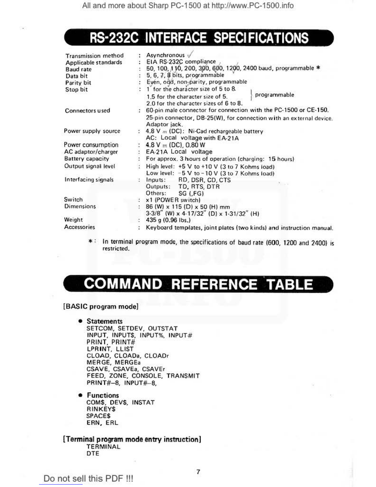
RS-232C interfacespecifications •
..
• . .
••
•
•.
•
...
•
•.•
...
•
..
- • . . . • • . . . . . • . . . . 7
Command referen
ce
1a
ble
.......
• _. _. . . . • • . . • . . . • • . . . . . . • . • . • •. . • . . . 7
RS
-
232C
. .
................
- .
..
•
...
•
.. ..
- . -
....
....
· · · • · · · . · · ·11
(1} Electri
ca
l c
ha
rac
teri
stle<
...
. -
.•.
..•.....
..
.
..
•
..
. • .
..
.••
. . .
..
· · · ·
11
(2} Func1ions
of
interfaci
ng
si
gnals .
•...
•
....•..•..•
..
.
...
.•.•.
••
...
·
..
11
Interfacing cable
..
_
........•.
. . .
..•.
..
•
...
•
......
••..
•
...•
•
..
· . · . . · · ·
13
Functions . . . . . . . . . . . . . . . . . . . . . . . . . . . . . . . . . . . . . . . . • . . . . . . . . . . . . . . . t 5
1.
Low
battery and power switch .
•........•.•.....
...
•..•...........
15
2. In
itial
state
upcn
power on after (
oFF
I key power
off
..
- . - - - . -
....
....
- . - .
16
BASIC program mode
..
•
....
- . - . . - - - . -
........
- . - . - . - - - - - . . . . • .
..
. . . - .
18
1. SET
COM
....
.
..•
.
••
.•.
. •
..
•
•.
•
...
· · . · • ·
·.
• · • • • · · · • · · · • · · -
18
2.
COMS
..
...•
. •
...
•.
. . .
.•.•
•
•....•
• .
..
••...
· •
..
•
......
· · · · ·
18
3.
SETDEV
......•
...
•
..••
.
•.
.
...
•
...•
·
..•
.
..
• - · • · • · • · • · · • • · · ·
19
4.
DEV$
...
.
....
, . . . . - . -
..
- . .
...
••
.
.•
.
..
• . . . · · · · · · • · · • · · • · · · ·
19
5, OVTSTAT . '
..
I
••
• '
••
• •
••
'
•••
' .
I.
' I ' .
..
. . . '
..
.
''
••.
• I
•••
..
19
6. I
NSTA
T
..
.....
• . - . - . - -
..
. . • . . . ,
•.•
•
..
..
- . .
..
· · · • • · · • · · · - · ·
2C
7.
INPUT
....
•
.•
• .
..
• . . . . -
•..
• -
..
•
...
.
...
- - . - • - · · - • · · · • · · · · · ·
20
8. INPUTS
..
• •
....
.
.•
- - - • - • - . •
...
•
..
. . . · - • - . • • · - · · · • · · • · - • · · -
22
9. INPUT%
..
...•
• .
.•...
.
..
.
..
.
.....•
• . .
.•
• - - • · · · · · · · · · · · · • · ·
22
1
0.
LPRINT
..•..•.....••...•.•..•.
•
.....•.•..
· · · · · · · • · · · · · · · · ·
23
11.
LUST
.•••....
.......•.
. .
•.•......•
· · ·
...
· · · · · · • · · · · • • · · · ·
27
12.
PA
INT
. _
........
- . - - .
..
- . -
..............
- · - · · · · · · • · · · • · · · ·
28
13.
CSA
VE, CSAVEa, CSAVEr.
PRINT
#
iranun
ission
lormat
_
..
- . . .
..•..
- •
..
- .
29
14.
LOADIN
G
BY
CLOAD.
CLOADa,
CLOADr.
MERGE, MERGEa . . .
..
•.
..
•
....
29
15.
CSAVE
.....•....
..
.
....
-
.•.
.....•..
..
. .
...
. .
...
..
• •
·•
· ·
·.
·
30
16. CSAVEa
.......
....
....
........•....
. . . . . · · · ·
...
· · · • · · • · · · · 31
17.
CSAVEr
...
• . .
••
. . •
•..•.•..
•.
....
· • • . . . - . - · - · • · • · · · · · · • • · · ·
32
18. C
LOAD
.
..
•
...
•
..•
-
....
- . . • . . • •
..
••
..•.
- - · · - • · • · · · • · · · · · · ·
32
19.
CLOAOa
. . • • • . . • . . • . . • • . . . . ·
•..
· · · · · · · • • · · • · · · · • • · · · · · • · · · · 32
20. C
LOA
Dr
..
.•....
-
....
..
-
..
.
•.
...
..
...
. . •
..
· · · · ·
.•..
· · · · • · · ·
33
21. MERGE
........•....
-
..
. .
...................
•
·•
- . . • · · - • · · ·
33
22.
ME
RGEa
.......
-
..
- . - - - . -
.......
-
........
· · - · · ·
..
· · · · · · · · ·
33
23.
Data
input
and
ou
lput
by
PRINT
#
or
INPUTlr statement • .
...
•.
•....
.•...
.
33
24.
PAINT#
. .
..•..
. •
....•..•..
....•
•
...•..
. -
..
-
..
- • .
..
• · · · - · · ·
34
25. I
NP
U
T#
............
. . . . -
...
.........
. .
..
· · - · •
••
..•
· · · • · · · · 34
26.
INPUT
#-8
.....
•
..
. . - - - . . . . . •
..•.
..
. · . . -
..
. • · . • · • · · · • • · • • · • ·
34
27.
PAINT
#-8
.•.•.•.
. . • .
.••...•
•
..•.......•..
- •
..
• . •
...
• · · • • · - · 34
28.
TRANSMIT
....
• .
..•
• .
••..
..
•
...•
..
• • · . · • . · • - · • · • • · · • • · • · · · ·
35
29.
RINKEY$
.
...•
•
•.•
..
.•
..
..
•
...
•
..
. •
..
- • - . - . .
.....
· • • · · • · · · ·
35
30.
ZONE
. •
..
...
• .
..
•
.....
..
••..
•
..•.•.
. .
..
. • · · • · · · · · • · · · · · · ·
35
31
.
EAN
.
.....•..
•
..
•
..
......
•
•.•......
· . . . . • -
..
- • · · · • · · • - · · ·
35
32.
ERL
.....
....
• .
..
• .
..
- . . . - • · · · · · · • · · · · · · · · - - · - • · · · • · · · · · · ·
35
33. SPACES .
.....
• - . -
...
. - . - . - - - · . · · · · - · · · · · · · - · · · · · · · · · · · · · ·
35
34.
FEED
.....
•....
..
••.
.•..
.•.•....•.....•..
· · · · · · · · · · • · · • · · ·
35
35
. CONSOLE
.•.••.••..•.•...•••
.•...
• • · • · · · - - · • - · • · · · · · · · · · · ·
36
1
Do
not
sell
th
is PDF !!!

r A
ll
and more about Sharp PC-1500
at
http://
www
.PC-1500.info
Page
Tenninal program mode . . .
...
. . . . . . . . . •
................
•
...
•
....
.
....
. .
37
1. TERMINAL .
.....
...
. .
...
. . . .
..
......
. . . . . . . . . . • .
.....
•
...
. 36
2.DTE
....
.
......
.. ..
. . .
.....
. . .
...
. .
...........
.
......
• .
...
38
3. Difference between TERMINAL statement and DTE statement . . . . . .
..
. . . . . . .
39
4. Symbols . . . . . .
.....
...
.
.. ..
.
...
. . . . .
.. ..
.
......
. .
..
. . . • .
...
39
5.
Code chart .
....
..
....
. . .
...
. . . . . .
..
.
..
....
.
....
•
..
. •
..
. . .
..
40
6.
Character buffer .
..
•
...
• . • .
..
•
...
•
...
• . . •
..
.•
••
. . . •
..
..
..
....
. 41
7. Keys
.......
...
. . . . . . .
...
•
...
• .
..
• . . • . . . .
.....
...
. . .
......
42
8. Repeat function .
.....
. • .
..
.
..
. . •
...
. . . . •
..
.•
. • . . . •
..
..
. • . .
..
.
43
9. Invalid keys .
..
. .
.....
• . •
...
• . . . •
..
•
...
• .
..
..
. .
..
•
......
. .
...
43
1
0.
Specialkeys
..
. . .
...
.
..
. • .
......
.
..
. : . . . . . .
..
•
..
. •
..
.
...
..
..
.
45
(1l Software keys
........
-.
. . .
..
....
.•
..
• .
.....
.
.....
•
..
•
..
...
45
12)
rn
key
...
.
...
..
.
..
. . . . . . . . . . .
..
. . . . . •
...
•
..
. • . . . . . . . .
46
(3)
I
""'
I key and key sy
mbo
ls
..
...
..
. . •
..
....
•.
. •
..
••
.
...
.
..
.
..
.
46
(4) Window key
_.,_;
......
. . . . . . . . . . . . . . . .
.......
..
•
...
•
.......
. 47
(5)
[C<
l /. 1-
IL
" I
..
.
...
. .
...
. . . . .
......
. .
...
......
....
.
..
49
(81
@"M
l . . .
...
.
...
.•.
•
...
•
..
. • . .
..
. .
•.
. •
..
• .
•••
..
•
..•
...
. .
49
(7) Paper feed key
.......
...
. •
..
.
.....
. . •
..
• . .
...
• . . . . . . • .
...
.
49
11. Transmission codes . . .
..
• . • .
..
.
......
•
..
. • . . •
...
. .
....
•
........
49
(1) Space
..
. .
.....
. . • . •
..
. • . . . . . .
..
. . • . . • .
....
. . . . •
..
•.
. . . .
49
(
2)
CR
. .
...
......
..
•
.....
• .
...
. . • .
..
. . . • .
..
. . .
......
•
....
.
49
(3)
BEL .
..
. • .
..
.
...
•
...
. . • .
....
.
..
.
••
. . . .
••
..
• .
....
. . . . .
..
49
(
4)
BKS
.
...
.....
.
...
. •
...
..
. .
..
...
. .
...
. . .
..
. • .
..
• . . . . .
...
49
(5) ESC
...
....
.
......
• . . . . . .
....
• . . . •
..
••
..
. . •
..
. •
..
. .
...
.
49
16)
Othercontrol codes . . . • . . . •
..
.
...
•
...
•
...
..•
..
..
..
.
..
. . . .
..
50
12
. Display
.. ..
.......
...
. •
...
•
..
•
...
•
...
.
...
..
.
..
. . . . .
..
..
. . . .
50
.
13.
Graphic codes .
...
.
.....
•
...
•
..
.
..
. . • . . • .
..
. .
....
• . . . . . • . . . . . S1
14.
Menu mode
........
...
...
. • . .
..
.
..
...
. • . . •
..
• . .
..........
..
.
52
15
. Menu select mode .
..
...
. . .
..
......
. . . •
..
.
...
. . .
..
••
....
.
••
.. ..
52
(1)
Terminal
..
. . .
..
. . • . .
..
••
..
• .
..
. .
.....
•
..
•
...
•
..
•
..
. • . .
..
52
(2)
Se
t
i.Ip
I • • • • I o o o o I • o 0 o O o • o • O • • o • 1 o I I O I • I • a • 1 l • ' I I l ' a I ; • < • 53
(3) Operate
..
. . . •
...
. . . . . .
..
.
....
.
...
.
..
. . • .
..
. • .
..
.
...
....
57
(4) Protocol
...
. . . .
..
. . . . .
...
. . • . . . • . . • . .
••
. • .
..
•
....
. . . .
...
58
(5) Output . .
...
...
..
• .
..
..
• . . . •
...
• . . .
...
• . • .
..
..
. . • . . •
..
. .
59
16.
RTS,
DTR
signals
...
..
.
...
..
. . .
..
•
...
• . .
...
...
•
..
.
..
. .
..
. . . . . .
62
17. Error codes
................
. . .
..
•
..
....
•
...
• . . . . . • . . . • .
•.
....
63
ParalleI interface . .
..
.. ..
.....
.
..
• .
..
•
....
.
....
. •
.....
•
...
•
..
•
...
.
..
. .
65
Specifications (Parallel port)
...
. • .
..
. . .
..
.
.....
• . .
..
..
...
..
. .
..
.
..
...
65
Para
lle
l interface . .
.. ..
....
..
• .
.. ..
. .
.....
. . . . .
...
..
. . . . . . .
..
. .
...
65
(1) Specifications
.......
. . .
..
. .
..
..
. .
..
. . . . • . •
..
. •
...
. . . .
.. ..
65
(2) Output connector
...
. . .
......
. . . . . . . . •
...
. . • . . . • . . .
..
. •
...
.
65
(3) Connector s
ig
nal desc
ri
pt
ions
..
. . . • . . . •
..
•
...
• . . . . . • .
..
. .
..
. . . .
66
(4) Timing ch
art
..
.
.........
.
..
..
..
. .
..
•
..
. • . .
...
....
. . .
..
. . .
66
1. Devices connectab
le
. . . . . .
....
...
. .
.. ..
.......
•
...
••
.
..
. .
.....
.
67
2.
Ca
utio
n beforeconnection • , . ,
.•
, , , , ,
..
•
..
. • .
..
.....
.•
. . .
..
. .
..
. .
67
3. Interfaci
ng
cable . .
...
.
..
.
...
. . . . . . . . • . . . • . .
.....
...
. .
.. ..
. . . . .
67
4.
St
atements . .
...
..
.
..
.
...
. . . . .
..
. . •
..
. • . . • . . , . .
••
. .
..
.
..
..
..
68
(1l
OPN
.....
..
...
...
..
..
. . . .
.•
...
•
..
....
. . •
..
....
. .
.. ..
....
68
(2)
CONSOLE
..
.
....
...
. . .
...
.. ..
...
.
..
. • . •
...
. • . . •
...
.
....
70
(3)
LPR
IN
T, LLIST. FEED .
...
..
........
..
...
..
. . . .
.•
.. ..
.
..
....
70
(4)
PR
INT#
·9 .
.......
..
. .
..
.
..
.......
.
..
. .
...
..
....
..
.
..
..
. . 70
5. I
ni
ti
al
state upon power on after [oiiJ key
po
we
r off . . .
..
.
....
. . . . . . .
....
70
6. Error code
..
. . .
...
.
.........
.
........
. .
...
.
..
. . . .
...
•
...
.
...
71
Power supply .
..
..
...
. .
......
• . •
...
•
..........
•
...
. . .
...
• .
..
. . . . . . . .
72
Program exampl
es.
. . . . . . . . . . • . • . . • . . . . • . . . . . . • • . . • . . . . . • . . . • . . . . . . . .
75
Sharp Corpor
at
ion and
/o
r its subs
id
ii
aries assume no responsibilities
or
obligations
to
any losses
or
d3m
a~s
that could arise through tl\e use of tl\e software progr
am
s employed in this instrue·
tion manual.
2
Do
notsell this PDF !!!

A
ll
and more about Sharp PC-1500
at
http://www.PC-1500.info
INTRODUCTION
Congratulations
on
your
purchase
of
this
SHARP
CE·158
Interface.
The
CE·158
is
an
optiona
l
device
for
uS<e
with
the
PC·
1500
Pocket
Compu
te
r
and
incorpor
a
tes
an
R:S·
232C
interface
and
a parallel
interface.
For
the
para
ll
el i
nterface.
refer
to
the descri
ption
on
an
d
after
page
65
.
SPECIAL NOTICE TO SHARP CUSTOMERS
1.
Yo
ur
CE
· 1
58
is
equipped
with
a recha
rg
eable
Ni-Cad
battery,
so
th
at
you
may
obtain
maxi
mum
eff
icie
ncy
from
your
unit, please read
th
.e i
nstr
uctions
below
be
fo
re
ope
r
at
i1)9
the
unit
for
the
f
irst
time
.
After
purchasing,
or
when stored
un
u.scd
for
over three
months.
we
re
co
mmend
that
you
rec
harg
e
the
ba
tt
ery
before
using
the
unit.
Simply
connect
the
AC
adaptor
(EA
·21A
only)
between
the
unit
and
the
wall o
ut
let.
When
recharging this
un
i
t,
turn
the
power
switch
OFF
. (See diagram
on
page
72.)
The
batteries
are fully
charged
alt
er 15
hours
.
OPERATIONAL NOTES
To
in
su
re tr<:iuble
-fr
ee
operation
of
your
CE-158
in
ter
face, we ask
you
to
observe
th
e
following
instructi
ons:
1.
Thi
s
interfa
ce
should
be k
ep
t in
ar
eas
fr
ee
from
e
xtr
eme
temp
e
rature
chaoges,
moisture
and
dus
t.
2. A
sof
t,
dfy
c
loth
shou
ld be
used
lo
clean
the
i
nterface
.
Do
not
use
any
solvent
or
wet
cl
oth
.
3. If service
of
your
interface
is
requ
ir
ed.
consu
lt
only
an
authori
z
ed
SHARP
servi
ce
cent
er.
4.
Keep
th
is
manual
for
further
refe
rence
.
The
te
rm ..
RS.232C
"
represent
s
the
specific
standard
of
th
e
EIA
(Ele
ctroni
c Industri
es
Associa·
tion in U.S.
A.).
Th
is
sta
nd
ard
spec
ifies
the
i
nter
faces
fo
r
use
in
da
ta
transm
ission
be
tweP.n
th
P.
mo
de
m
and
co
m·
mu
n
ication
contro
l d
ev
ices, and the t
ransmiss
i
on
of
di
gita
l bi
nary
series
da
ta,
contro
l signals
and
timing signa
ls
between
the
mod
em
and
data
te
rminal
P.
Qu
ipme
nt.
The
RS·232C
inter
fa
ce
is o
ne
of
dev
ices
fo
r general
use
in in
fo
rmat
ion
exchang
es
betwec
1'
d~
t
a
process
ing
equ
ipmen
t
an
d data
te
r
mina
l
equ
i
pme
nt.
The
SHARP
'
CE
·158 (
RS
·
232C
/
in
ter
f
ac
el
is desig
ne
d to
comply
w
it
h the EIA
sta
ndar(IS.
However.
we
cannot
guarantee
t
hat
the
CE·
158
wi
ll
work
with
all
so
·call
ed
..IRS·
232C
co
mpat
ible..
devi
ces.
Nor
do
we
co
mm
it ourselves
to
pr
ovide
engine
ering
and
p
rog
ramm
ing
suppor
t for such applica·
tions
or
any
othe
r
specia
l
custom
-
use
si
tuat
ion.
F
or
ac
tua
l
use
of
the CE·
158,
r
ead
th
is in
st
ru
ct
ion
manu
al ca
re
fully
and
urriderstand the da
ta
t
er
·
minal
equ
i
pment
.
This
ins
truct
i
on
manual contains the inform
atio
n
nee
ded
for in
format
ion
exchange
w
it
h
data
pr
o ·
cess
in
g
equ
ip
me
nt.
Do
notsell this PDF !!! 3

A
ll
and more about Sharp PC-1500
at
http://www.PC-1500.info
Seria
.I interface
The
serial interface
is
used
to
make
communication {data transfer} with information carried
on
a single signal line.
Serial signals carried
on
the signal line of the interface should ei
th
er
be handl
ed
in the star
t/
stop
or asynchronous mode. Parallel signals a
re
fir
st converted
into
~r
ia
l
signals before being
transmitted. a
nd
the signals received are then converted from serial
to
parallel.
In
addition
to
the data
signal
line, there
are
a number
of
signal lines required for exchang-
ing operating
status
on sending and receiving sides, though
they
vary depending on
the
device used.
The
serial interface will
of
fer a
wide
range
of
applications when used in conjunction
with
the
numbe
r of peripheral units
that
are equipped with the RS·232C i
nterfa
ce, such as:
• Acoustic couplers that
perform
data communication via the
te
lephone ne
two
rk,
• Printer,
• X·
Yplotter,
• Instrument device,
• Personal
computef,
•
Video
display
unit
.
4
Do
notsell this PDF !!!

A
ll
and more about Sharp PC-1500
at
http://www.PC-1500.info
CE-158
Power swit<:h
PC·
1500
Joint
plate
(A)
PC·
1500 -
:::--.-.__
CE
-150
"""
.
.,.
z
;;~
;;;----_
--
/
--..
-->
·v .
..
.1
:fi·
.:.>.....,•4>J
~
~
;r~
--
.
......
..
~
-
"
...
'-J'
•
.....
-
..
.;.~
/.
~':...
··
~
.r
--
-
---
'--·
'•
......
--~
..
..
"
.::>
•
.....;,
t:..
;,
't-il -
·
--~
•
..,
•
~
•
;.,J
/,~-
.::.._...;:::_::-
·
......
.
..
.
...
.:_::;,·
~
-/
~
·
-
·
-
~~
/.
CE·158 -
//
.,..._,_,
~
~
·
:
~
; '
f'
. •
..
.
~
. ·
-,
b'
~
I
'
~-
-
-
..
,";_,...
.J
//
/
Conne
ctor
for
5
~
-
..
.
,_
""'"-"
....
..
.
,t4
parallel inte
r.
face
--
-H-
...,.;.'.
-
-:i::.,,.~
~
..
·
~-.
l
~
\V!
~
~
•
AC
ada
pto
r
-
-~
"-
ef.':1'§!P"'
•
'-
~
connection jack
~
¥'
1 0
""'
Co
nne
cto
r Joint plate !B)
for
RS·232C
Do
notsell this PDF !!! 5

All and more about Sharp PC-1500
at
http:l/www.PC-1500.info
RS-232C INTERFACE
6
Do notsell
th
is PDF !!!

A
ll
and more about Sharp PC
-1
500
at
http://www.PC-1500.info
T
ransm
issi
on
method
Applicablest
anda
r
ds
Ba
ud
r
ate
Data
bit
Pa
rit
v.
bi
t
Stop b
it
Con
nee:
tors uscd
Po
wer
supp
ly
source
Power consumption
AC
ada
p
tor/
charger
Ba
1te
ry
ca
pacity
Outpu
t signal level
Interfacing
signals
S\Yitch
D
im
ensions
Weight
Acc
e
ssor
ies
Asynch
r
onous
,/
EIA
RS
·232C
c:omp
li')['ceJ l
50. 100.1
1
.J
-0
. 200, 3
SJ
O,
!i,JJO
, 12
51
0. 2400 baud, progra
mmable*
5, 6,·"l,
~b
it
s
,
pr
ogrammable
E
j'6n
.
o ~d
.
n
o
r
~
P
ar
it
y
,
pr
ogra
mm
able
1 for the
chara
cter size of 5
to
8.
1.5
for
the
chara
cter s
it
e of 5.
2.0
fo
r the character sizes of 6 to
8.
f programmable
60·pin male
con
nector for co
nne
ctio
n
with
the I
PC·
1500
or
CE·150.
25·pin
co
rln
e-c
to
r,
OB-25(W
},
f
or
conne
ct
ion
v1ith
an
C><
tCrrla l
de
vice.
Ad
apto
r ja
ck
.
4.8 V
.
~
(DC): Ni·Cad rech
arg
eab
le battery
AC: Local
vo
ltage w
it
h EA·2
1A
4.8 V
"'
(DC
), 0.
80
W
EA·21A Local v
olta
ge
For a
l)p
rox.
3 h
ours
of
operation
(c
hargi
ng:
15
h
ou
rs}
High
leve
l: +5 V to +10 V
(3
to
7 Kohms load)
Low l
ev
el: - 5 V to - 10 V (3 to 7 Kohms lo
ad)
lnpUts: RD.
DS
R, CD, CTS
Outp
ut
s: TD. RTS, DTR
Oth
er
s:
SG
{.FGJ
x1 (POWER switchl
86
(W
) x 115
(D
Jx 50
(H)
mm
3·3/8"
(W
) x 4·17/32"
(D)
x 1·31/3
2"
(HI
435 g {0.96 lbs
.}
Ke
yboard
temp
l
ate
s. j
oin
t p
lat
es
(tw
o kinds)
an
d instruction m
an
ua
l.
*:
In
t~
r
minal
program mod
e,
th
e:
spe
ci
ficati
ons
of
baud
rate (600, 1200 and 2400) is
restr
i
cted
.
•
[BASIC program
mode
]
• Statements
SETCOM,
SE
T
DEV
,
OU
T
STAT
INPU
T,
INPUT
S,
I
NP
UT%, INPUT#
PRINT.
PRIN
T#
L
PRINT,
LU
ST
CLOAD,
CLOADa, CL
OADr
MERGE, MERGEa
CSAV
E,
CSAVEa, CSAVEr
FEED, ZONE, CONSOLE, TRANSMIT
PRINIT#-8,
INPUT
#-
8,
• Functions
COM.$. DEVS. INSTAT
RINK
E
YS
SPACES
ERN.
ER
L
[Terminal program mode entry instruction)
TE
RMINAL
DTE
7
Do
notsell
th
is PDF !!!

A
ll
and more about Sharp PC-1500
at
http://www.PC-1500.info
0 : Yes. X
No
Com~nd
Manual e
xecut
i
on
Pro"3m
Function
Exomple RUN PRO RESERVE
execution
[Statement)
SE
TC
OM
SETCOM
300
.7,E,1 0 0 0 0 Sets
communication
pa
·
rameters.
SETCOM 0 0 0 0 Initializes
commu
nicati
on
parameters.
. Assigns
communication
de·
SETOEV SETDEV Kl
.PO
0 0 0 0
vice.
SETDEV 0 0 0 0 Releases
communication
<!<!Vice.
OUT
ST
AT
OUTSTATO
0 0 0 0
Sets
status
of
the RS-232C
port
output
signals.
.
Subst
i
tutes
th
e
variable
INPUT INPUT
"A•";A
x x x 0 wi
th
t
he
i
npu
t
data
thru
the
RS.232C
port.
INPUTS INPUTS
"A
•
";A
x x x 0 Same as above.
IN
PUT
% INPUT%
A$(*)
0 0 0 0 Same
as
above.
INP
UT#
INPUT
#A
0 0 0 0
Same
as
abo
ve,
PRINT
PRINT 1
23
0 0 0 0 Sends data
thr
u the RS·
232C
port.
PRINT#
PRINT
#A
0 0 0
()
Same as above.
L
PRINT
LPR INT 1
23
0 0 0 0 Same as above.
LUS
T L
UST
10
,
100
0 0 0 0 Sen
ds
program
thru
the RS·
232C
port.
CLO
AD
CLOAD
"FILE"
0 0 0 x Loads program
th
ru
t
he
RS·232C
port.
L
oad
s
program
thru
the
CL
OAOa
CLOAOa 0 0 x x RS·2
32C
por
t in ASCII
code.
CL
OADr
CLOAOr 0 0 0 x Loads reserve program
th
ru
the RS
·2
32C
po
rt.
CSA
VE
CSAVE
"FILE"
0 0 0 0
Saves
progran1 or r
e.serve
program th
ru
the
RS
·23
2C
por-1.
Saves p..ogram
thru
lhe
CSAVEa CSAVEa 0 0 0 0 RS·232C
port
in
ASCII
code
.
CSAVEr CSAVEr 0 0 0 0 Saves reserve
program
thru
the
RS·232C
port.
F
EED
FE
ED 5 0 0 0 0 Sends
the
E
NO
code.
Specifies block length
du
r·
ZONE
ZONE
20
0 0 0 0 ing
dataoutput
by
LPRINT
sta
te
men
t.
Specif
ie
s digitsfline
and
the
CONSOLE CONSOLE
80.0
0 0 0 0 kind
of
ENO
code
.
8
Do
not
sell this
PDF
!!!

A
ll
and more about Sharp PC-1500
at
http://www.PC-1500.info
1-
----Co~m_m_•_n_d
_ _
__
-+
_
Ma
~
n_u_
.,_
l~•-x
ecu
_ _tio_·
-"--1
Program
Example RUN PRO RESERVE execution
TRANS
.
MI
T TR
ANSMIT
BREAK
, 10
MERGE MERGE
MERGEa MERGEa
PR
IN
T#
-8
.
PR
INT#-
8.
123
INPVT
#-
8,
INPVT
#-
8,
A
(Function1]
COM
S
COMS
DEVS DEVS
IN.
STAT
INST
AT
R
INKEYS
RINKEYS
SPACES SPACES (
10
1
ER
N ERN
ERL ERL
0 0
0 0
0 0
0 0
0 0
()
0
0 0
0 0
0 0
0 0
0 0
0 0
(Terminal program en
try
instructionI
TE
RMINAL TERMINAL 0 0
DTE DTE 0 0
Do
notsell this PDF !!! 9
0
x
x
0
0
0
0
0
0
0
0
0
0
0
0
x
x
0
0
0
0
0
0
0
0
0
0
0
Function
Sends
lo
ng
spaces
(pad·
ding).
Links progtan
'I
with the
progr
am
sent thru the
RS
·
232C port.
L
in
ks
procJra
rn
\vith the
program sent th
ru
the RS·
232C
po
rt
in ASC
II
code.
Sends
da
ra
out
thru t
he
RS·232C port.
Substi
tutes the vatiablc
with
the data
sen
t th1ou9h
the RS·232C
po
rt.
Cha:racter·stri
ng
'-'Ji
th
\•Jhi
ch
communication paramet
ers
arc
s
e-t.
Character st
rin
g
with
\•Jhi
ch
communication device
is
set.
De
sign
ate
s RS·232C
port
handshake signal state.
Character stnng
wit
h which
l
ast
one
byte
code
inp
ut
th
ru
the
RS
·232C
port
im
·
med
iately before execu·
ti
on
of command
is
set.
Character string consisting
of
sp
ecified n
um
ber of
sp
ac
e
s.
D
es
ignates
error
code,
Designates error Iine num.
ber.
De
fa
ult
Protocol: XON/XOFF
ON.
ECHO OFF
D
efault
Protocol: XONIXOFF
OFF,
ECHO
ON
P
ara
meter: 300 Baud
7 bits data
Even
Parity
1 Stop b
it

A
ll
and more about Sharp PC
-1
500
at
http://www.PC-1500.info
Serial signal
Transmit and receive data are handled
in
a form
of
serial signal as illustrat
ed
below
. (Waveform
as
observed
at
the
1/0 pin
of
the
DB·
·25W.I
Absence
of
data
must
be
stop
bits.
LSB
(M
SB
l
~~·
.......,.......,.......
·.-
.....
.....
-....-'-..-.-....-
--
.-..•..--.-
"p"
....
Stop
bit
Start:
Data : : : : : : : :
anty
--
--~
bit :..
'?!!
..
·.
~
..
·-
-·-
·'·
-·
-·.
--
~
--
--.
-.:.....
..
i..
..
....;.
..
·-·
..
:
..
.
·-
..
.:.
'?!!
...
a 1 2 3 4
(SJ
(6) (7)
Stop
:s1o
p Next:
..
.
bit
;b
it
start \
..
3 (1) bit
Data bits. 5.
6,
7. parity bit, and
stop
bit 1 may
no
t exist, depending
on
the
commun
ication
parameter
used.
(11
Transmissionspeed (baud rate)
Represcnts·number
of
bits tran.
sl')>itted
per second, incl
ud
ing
the
start bit, data bit, pari
ty
bit. and
stop
bit.
(21
Character length
Represents number
of
bitsused to comprise a single transmission character.
(3)
Parity
bit
A
bit
attached
next
to
the
Ian
data bit (MSB). Three modes
of
non-parity, even parity,
and odd
parity
can
be
chosen
to
check data accuracy.
{4)
Stop
bit(s)
Bit(s) attached
next
to
·the data
bit
or parity bit;
th
e size varies fr
om
1to1.
5, and
2.
Interfacingsignal
Signal leve
ls
at
the
1/0 pins of
the
DB-25W connector shall be as follows:
Input
signal
High
le
ve
l (SPACE
or
ON
s~ate
of signal) : +(3
to
15) V
Low level {MARK or
OFF
stat
e
of
siqnal):
-(3
to
15) V
Output
signal
High level:
+{5
to
10) V
Low level: -
15
to
10) V
As
lhe
level
of
the
output
signal i·s measured with
the
load
of
3
to
7 Kohms with the cable
length of 1 meter. Please note
that
there may
be
a casewhen the above condiii
on
is
not
met
.
if
the load
is
out
of
above
rang
e
or
the cable length is longer,
or
the
cable capacity is larger.
10
Do
notsell
th
is PDF !!!

A
ll
and more about Sharp PC-1500
at
http://www.PC-1500.info
RS-232C
T
he
RS
·23
2C is
the
standards
of
the
EIA (Electronics
Indust
r
ies
Associ
at
i
on)
wh
ic
h has
been
eita
bli
ihed
to
se
t the standard interfacing
requi
r
eme
na betwe
en
the data te
rmi
na
l
un
it
and
the
data
co
m
munication
unit.
The
CE·
158
has
been
deve
l
oped
to
meet
those
standards
.
Main
parts
.
of
these
standa
r
ds
define
the
follow
ing cond
itio
ns:
(1) EJectr ical
charac
teristics
(2)
Mechan
ical ch
aracter
istics
of
the
interface u
nit
(3).
Functions
of i
nterlacing
signals
(1) Electrical characteristics
1} In
put
signal
be
low - 3 V is regarded as MA RK.
and
above +3 V as SPACE.
2t
Load side impedan
ce
shall be a d
ir
ec
t
curr
ent
resistan
ce
of
more
than
3 Kohrns against an
impressed voltage of less
th
an
25
V.
or
le
ss
th
an 7 Kohms against
an
i
mp
ress
ed
voltage of
3to25V
.
3)
Output
sign•I in MAR K
st
•
te
s
h•
ll
be
-5
to
-15
V
or
out
put
si
gn•
I in SPACE
state
sha
ll
be+
5 V
to+
15V.
4)
Eff
ec
t ive l
oad
capaci
ta
nce
at
the
end shall be less t
han
2500 p
F.
in
clvding c
ab
le
capac
·
it
ance
.
(2)
Functions
of
interfacing signa
ls
Connec
tor s
ig
nal
configurat
i
on
T
he
DB
·2
5{W)
connector
co
mes
with
the
CE·
158.
O
OO
O O @
Q)®
@CD
O)
(Z)
()
0 0 0 0 0
·
~
0 0 0 ()
() ()
Con
nect
or Pin Configuration
Ac
tually, ei
ght
pi
ns are used o
ut
of t
wenty
f
iv
e pins.
NOTE:
Different
signal
con
nections
may
be
required
depe
nd
in
g
on
si
gna
ls u
sed
by
th
e
device connected.
Use
the
meta
l
case
(type
0824659).
Do
notsell this PDF !!! 11

All and more about Sharp PC-1500
at
http
:l/
www
.PC-1500.info
Pin assignment
Pin
No
.
2
3
4
5
6
7
8
20
hem
Symbol
I
n/
Out
Fu
nc11on
Rem11b
Transm
it
Data
TO
Out
Se-
nd
dat
a ±(
5-1
0)
v
oe
\ignal
'
Re
ce
ive
Data
RO
lo Recei
ve
d
at
a ! (5- 1SI VOC 11
9n
ail
h
~
o
dem
transmi
ss
i
on
cn
1ucr
co
nt
rol. O FF
in
Rcquest·To·Send
RT
S Ou t
ON
N
>I
: Send ea
rn
er. Powur
OFF
fV
- 1:
St
op
ca
n •C•.
01,
,
O
a13
tra
t1
vn
1
ss
1on
coc1
1t
ol.
OFF
when a
Clear·To-Send
CTS
In
ON:
Data uansm1ssron ef'll)bl
fd
.
Cable
isn't
OFF:
Data 1r1nvn1ss1
on
d•
s
ab~d
.
connt.'Cltd.
to
t
odttn
Slitus
1ndic
..
1or.
ONwhcn1
Data
Set
Ready
OSR
lo
ON
: W.Odem
rtady
to
~ndJr~
1
11e.
c.abft
.sn'1
OFF
:
Modem
no1
r~~Y
to
wnd
/1
ece1Y
t.
connected.
SignalGround
SG
Provide
s
refl'fence
volt&ye
itve
l
with
respec
t
to
all
in
ter
facing s1
gni
l.
C'
arr
1cc d
ete
ction. ON wh
en
a
Ca
rr
ier
Detect
CD In ON: c a
;ti
cr sigoal f
(.'C41
•
vc
d. cable
is
n' t
OFF
: C\ln i
c:
r s1!1
na
l not nlceived.
co
n
ncc
u
:IJ
.
Da
ta
Terminal
Stat
us
in
dic
atio
n
on
1
~tm
1
nal
iidc
rc
e.1
58
>.
OFF
Hl
Ready
OTA
Out
ON
: T
erm
inal re.xiv. Power
OFF:
T
erm
in
al
no1
r
~i.ldv
.
On.
NOTE : Input signal
within•
range
of
•5
to
•15
V and
output
signal within a range of • 5 to
•10 V will repre,..nt
ON
state, a
nd
input signal
within
a range
of
- 5
to
15
V and
outpUt signal within a ran
ge
of - 5 to - 10 V will represent OFF s
tat
e,
12
Do notsell
th
is PDF !!!

A
ll
and more about Sharp PC
-1
500 at http://www.PC-1500.info
INTERFACING CABLE
CAUTION: The illustrations are
for
typical equipment
and
are
used
as
exampl
es
only.,
Your
part
ic
ular equipment manual should be
consu
lted
for
specific cable connections.
Connection with acoustic coupler
Conne
ct
cable signal lines in the
follow
ing manner when the
unit
is
connected
with
an
acoustic
coup
le
r.
CE·
158side (08-25MI
2 TD
3
RO
4
RTS
5
CTS
6
DSR
7
SG
8 co
Connection with Personal Computer
Connect
cab
le signal lin
es
in a manner
Personal
Computer.
CE.
158
side
(DB-25M)
2 TO
3
RD
4
RTS
5 C
TS
D
6
DSR
7
SG
8 CD
20
DTR
Do
notsell this PDF !!!
Accoustic coupl
er
side
!DB·25Ml
2 T D
3
RD
4 R T S
5
CTS
6 DS R
7
SG
8
co
described bel
ow
, when the u.nit is
connect
ed
·.
vith
Persona
l Computer
side
(OB
-25MI
2 TO
3 RO
4 R T $
5
CTS
6
DS
IR
7
SG
8 CD
20 O
TR
13

A
ll
and more about Sharp PC-1500
at
http://www.PC-1500.info
To
make
connection
with
other
peripheral units,
check
specifications
of
the
peripheral
unit
if
they
should
match
with
th
ose
of
the
CE·
158.
and
use
an
appropriate
cab
le
to
connect
with
.
Cau
tions
described below are
basic
reQuirements
and
they
are
ex
.
empt
in
terms
of
software
.
You
will have
to
judge
for
yourself
after
reading
the
command
description.
(11· Electrical characteristics
Make
sure
that
it
is in
compliance
with
the
EIA RS-232C
stand
a:rds.
(2) Transmission
method
The
CE-158
is
operated
in
the
a:synchronous mode,
not
the
synchronous
mode
.
{3) Transmission procedure
No
procedure is used.
(4) Baud rate
and
transmission
data
format
Make
sure
that
it
is in compliance
wit
h
baud
rate
and
data
format.
{5)
Code
system
This
unit
us~s
the
ASCII
code
o:r
internal
codes
in
use.
(6)
Connector
Use
the
25·pin
DB·25{W) conne<:tor.
(7)
In
t
erfac
ing signal
As
fou
r inp
ut
signal lin
es
and three
outpu
t signal lines are used,
it
w
ill
r
eQ
u
ir
e
fou
r li
ne
s
for signal input.
In
case
one
output
line
shou
ld
be
connec
ted
with
two
i
npu
t
li
nes,
at
tc
n·
tion
must
be
paid
to
the load resi
stance
as
it
may
no
t
mee
! with the EIA r
equ
irem
en
t.
{8)
Signal flow
to
per
i
phera
l
Because this u
nit
is a
da
ta
terminal,
conn
ect
or
signals
ar
e
designed
for t
ran
smission he·
t
......een
the
data
te
rm
inal
and
the
data
co
mmu
n
icat
ion
un
it.
Ther
efore, it neeels
to
1.1
se
1hl!
cab
le
where
signal flow is i
nverted,
if
th
e
per
ipheral
un
it is al
so
a
data
term
in
al. (S
ee
figure
below.)
The
majoritY
of
data
commu
1
)icatio
n units
are
acoust
ic
coupler
s,
but
th
e p
fi
ntf!(
X·Y
plo
tter.
personal
eomputer,
ete
.,
are
data
termina
l
in
every
tase
.
2 TD TD 2
3 RD RD 3
4
RTS
RT
S 4
5
CTS
CTS
5
6
DSR
D
SR
6
7 SG SG 7
8 CD
~
....
........ co 8
20
OTR
DT R
20
CE·
158
Peripheral
•
So
far as CD
and
DSR
concerned,
it
will
be
regarded as t
he
ON
state
when
ope
n, wh
il
e
other
inputs
are
regarded as
the
OFF
stat
e.
• When OTA is
connected
to
CD
in
add
it
ion
to
DSR.
it
causes h0
ot
h
input
si
gna
l leve
ls
to
go
out
of
given ratings
(+3
-
15
V
and
-3
-
15
V)
dissatisfying
the
EIA r
equ
ir
ements
.
14
Do
notsell this PDF !!!

All and more about Sharp PC-1500
at
http://www.PC-1500.info
FUNCTIONS
This
uni
t
has
t
he
fo
ll
ow
ing
funct
ion
s:
1. BASIC program
mode
2. Terminal program
mode
The
11',0d
e l
controls
program and
data
tr
onsaction
using the
BASIC
program comrtHtnds to
pcrforin
the
follo
..
ving
app
lication
s:
• Data
exc
hange w
it
h personal computt1r,
• Listing o f prog
ra
m
con
tents
and
operational
result
on
pr
i
nter
.
•
Proc
ess
ing
of
measu
re
me
nt
data f
rom
instrumentation
.
On
the
o
th
er
~
·
1a
nd,
the
mode
2 funct
iOflS
as a terminal
un
it ""i
tho
ut
need
of
preparing
program,
for instance:
•
As
the
r
equired
item is specified
to
th e
data
base th
rough
the
k
eyboard
.
the
rele
v
an
t
i
nforma
ti
on
1s
fetched
oo
the
display
Of
printed
on
th
e
pr
i
nter.
• Used lo'
the
output
un
it
of
a
peripheral
u
ni
t
that
i
nco
r
porates
no outJ)Ut fea
ture.
Wh
en
th
e CE·
158
is
connected
w
ith
th
o PC
1500
or
CE·150,
be
sure
to
turn
off
the
compu
ter
IPC·
1500)
.
As
the
C
E-
158
is
con
trolled
by
command
sta
t
emen
ts
and
functi
ons
us
ed
for
da
ta
t
ran
s
mi
~
\.1
0
n
v
1;.
1
the HS·232C
po
rt,
da
ta transmission
with
the peripheral uni t mus1 be con11o
ll
r:d by n'lcans of
1h
os.e
co
n1rna;nd st
ateme
nts.
St
i:l
tr.1
i1c
n1s
and fun
ctions
pe
rt
i
ne
nt
to
this
un
it hold c
xccutio1'I
un
less
RS
·?32C
poi
t
11
lp111
su
1
na
ls.
CT
S.
CD.
and
DSR.
are
all
act
i
ve.
(Executi
on
wi
ll
take
1>l
aee
a1
so
on
as
all
of
these
1ig11a
l
go
activo
.)
Thcrc
t
orc,
th
e-
s
tat
e
of
t
he
periphe
ra
l
un
it
mu
st t
>e
checked
us
i
ng
the
INST
AT
fu
nc
ti
on
boforc
o
xe·
cuti
on
of
ch
e
s;
tatcmcnt.
Because
th
e s
tatus
output
signals to
the
peripheral
unit,
RTS
aod
OTR.
are
~
nact1v
e
after
po
1
A1
cr
on
.
th
ey
hav
e
to
be
turned
act
ive vsing
the
OUTS
T
AT
statement
before
comm
encement
of
da
ta trOtlsnlis·
sion.
~PORTAf'il:
Th
is un11
has
to
be
connec
t
ed
vii
th
the
PC
·
1500
\vhen
program
i.s
created
using s
tat
emen
ts
an
d
funct
i
ons
pertinent
to
t
he
CE
-
158
.
01h
e
rv1
ise. it
v1
1ll
not
insure
proper
ope
r
a11
on a1t
he
ume
of
program
ex
ecut
i
on.
Also.
i1
needs
connection
\vith
th
e PC·1
500
\•1h
en
th
e
prog
r
am
that
uses
statcnl
cnts
and
func·
ti
ons
pertinen
t to t
he
CE
·
158
is ex
ecuted
or
hs
t
ed
.
1. Low
battery
and POWER switch
The
CE· 15B is
ope
r
at
ed by
the
inte
rnal
Ni
·Cad ba
tt
erie<
{AA
x 4).
(1)
Wh
~n
the PC·1500 POWER switch i• tu
rnod
on
aft
er tuming
th
e CE- 1
58
POWER ;w1t
r.
h
on.
power
is
su
pplied
10
the
CE·t
5B
from
the
se
Ni·Cad batteries.
(2)
When
the
PC·1
500
POWER
switch
is
turn
ed
off
in above
cond
iti
on
(1),
it
turn
s o
ff
th
e
bane
ry
power
supply
10
t
he
CE·1SS..
(3)
Turn
off
th
e CE·15B POWER swit
ch
10
sa
ve unnecessary
powe
r
con
s
umpt
ion
when
the
exte
rnal device is
not
operat
ing.
{NOTE)
To
execute
the
instr
uction
of
the
CE·15
8.
be
sure
to tu
rn
on
the
CE
·
t58
powc1
switch.
W
hen
the
instruc
t
ion
is
ex
ecu
t
ed
with
the
CE
·
158
power
off.
the
E
RROR
50
will
occur.
To
change
the
program.
the
CE·
158
powe.
switch
ma
y
be
in
any
oosition.
Do
notsell
th
is PDF !!!
15

A
ll
and more about Sharp PC-1500
at
http://www.PC-1500.info
The
following messagge may
be
put
on
the
display of
the
PC-1
!>DO
wh
en
the CE·
158
POWER
switch
is
off
beforeturning
on
the
PC-1500
POWER
switch
or
when power supply from
Ni-Ca
d
b.atteries
is
low.
(~
:C_H_E
_C_K
_
S
______
_
~
)
In
thiscase, recharge
the
battery
or
tum
on
the CE·158
POWER
switch.
When the CE-158
is
connected
with
the
CE
·1
50
and
the
battery voltage
of
the
CE·150
is
also
low,
(
:
_
~
.
~
.
ECK
68 _
___
)
is
displayed.
Under the following condition,
(
~
N
_
E
_
W
_
0
~
?
_
:C
_
H
_
E
_
C
_
K
~_
S
_
·
~~~~
~~~~~
)
ma
y be displayed. However,
NEW
JiJ
I
<•n•
1 operation
is
not
requ
ired
in this case.
• When
the
PC·1500
is
turned
ON under the
Auto
Power
Off
condition
• And CE·158 power is OFF
or
the battery
of
CE
·
158
is
low.
In dlis case,
win
on
the CE-158 POWER switch or recharge
the
battery, and press the l« ikey
to
clean the
PC·
1500
.
(NOTE) Do
not
connect
or
disconnect t
he
AC
adaptor
to
the
CE·158. when the program
is
executed with the P
C·
1500.
Otherwise, the ERROR
50
may occur.
Supply voltage
of
PC
-
1500
The
CE-158
will not perform a proper operation when the battery indicator " ·
"lo
oks
v;eak
as
seen from the
fr-o
nt,
as
it alerts l
ow
battery
condit
ion
for
the
PC·
1500.
The b
att
ery indicator
is
locat
ed
to
t
he
right side
of
the
display.
In
such a case, either replace
the
bat
tery
of
the
PC·
1500, with
the
fresh one
or
co·nnect the
AC
adaptor
EA·
150 into the ada
pt
or j
ar.k
of the
PC·1500.
The
EA·
150
is an
AC
adaptor supplied with for the Printer/Cassette Interface CE·150.
2. Initial state
after
power
on
after
[
o"
) key power off.
When power
is
turned
on
to
the
PC·1500. the CE·158
is
placed
in
the following initial state.
Item Parameter
Des.er
iption
SETCOM
300. 8, N, 1
SE
TD
EV
All
devices are cleared.
OUTSTAT 3 DTR and RTS
=OFF
CONSOLE 0,0 END code =
CR
code
ZONE
13
TAB 0
Although power·on after auto-power-off resumes
the
same <:ondition
im
mediately before
auto·power·otf,
it
may
be
in
the:
state of
"OUTSTAT
3"
until a command
is
executed for the
CE-158
,
16
Do
notsell this PDF !!!

All and more about Sharp PC-1500
at
http://www.PC-1500.info
Signal
state
at
power-off
(1)
Out;pUt signals
from
the
CE·158
such
as
TD,
RTS,
and
DTR,
become
unstoble
w
hen
th
e
f
ollowing
condit
ion
is
met
wh
ilesen
ding
or
rece
iving
progr
ams
or data
via
the
CE·
158
.
Ca)
Power
on
and
off
of
the
PC
t
500
.
(b)
M
anipulation
of
the
POWER
sw
i
tch
of
the
CE·158.
(c) Releasing
the
low
battery
cond
i
tion
of
the
CE-158
alter
r
echa
rge.
(d)
Man
i
pulation
of
the
AC
adapto
r
EA
·
21A.
If tf1e opposite
sid
e is in receiving
operation
at
this
poi1
'lt,
it
may
read
unstab
le
da
1a as
though
d
ata
is rece
iv
ed. In
suc
h an
event,
observe
one
of
the
following
meth
ods.
•
Sta
rt
the exec
uti
on
all
over again {trans·fer
of
prograrn,
for
exi)
mplc).
•
Send
t
he
heade
r tOgether
wh
en
the
PC·
15
00
se
nd
s the data
out
so
that the
r
cccMn~
$
od
e
will
receive t
he
data that fo
ll
ows
to
t
he
header. {Exar
nple
will
be ir1
F
1
gurt
~
hc
10
.....
.)
• S
end
the
same
co
nt
en
ts of t
he
data f
or
th
ree
times wh
en
th
e
PC
·1
500
se
nds
d\1t
l1
out.
So
that
the
receiving sidewill receive the similar
data
fo
r
mor
e
than
two
tu'nes.
(21
N
ot
e
tha
t
the
opposite
si
cfe
may
sometrmc
assume
the
CE-
158
ou
tput
si9r>o
l
(RTS,
DTRI
to be
ON
sta
te
when
the
PC
·
1500
or
CE·
158 is in O
n•
or l
ol
1owing cond1t1
om.
(e I
PC
·
1500
in
the
po
wer
off
state.
(fl
The POWER
sw
itch
of
the
CE
·
158
is
off.
(g)
The
CE-158 in low
battery
cond
i
tion
.
(h)
The
CE·
158
is
not
connected
with
the
PC
·
\500
or
CE·\50
that
is
connected
wi
th
the
PC
-
1500.
(Ex
ample):
Shown
below
is
a
program
example
that
the
Pe,.onal
Computer
proce
sses
the
data
sent
from
the
PC·1
500.
provided
that
the P
ersona
l
Computer
is in recciv·
ing
cond
i
tion
OJt
<Jll
times
.
PC·t 500
f-
C
E-1
58
12 SETCOM
3
0~.
8.
E.1
20
SE
TO
EV
PO.
Kl
32
OU
TS
TAT
0
ti2
LPRINT
"ABC"
11~
I
NP
UT
8$
12i
IF
~$
"Y"THEN100
130
SCTOEV
PO
20i L
PR
I
NT
A$
9H
ENO
Do
notsell this PDF !!!
Personal
Compu
t
er
103
RSMOOE
A.R
S.
TB
.M71.RX1
3l3 ON
ERROR
GOTO
r
in
Send
of
header
..
ABC"
31i
RSI
A
AS
···
Receive
of
h
ead
er
:lli
roR
o=·
TO
>ii
: NE XTO
33~
IF
RIGHT$
(AS
.3
"ABC"
Send
of
data
..
A$
"
Processing
of
received
~ta
I
Error
process
r
outine
I
[
for
receiv
i
ng
error
~
incorrect
header)
17
THEN
RS
O A
.N
.
:GOT0310
···
·Head
er
co
nf
ir
med
400RS
I
AA$
see
END
1~
FOR
O=i
TO
see
:
NEX
T 0
1816
RS
M
OOE
A.RB
.
T8
.
M71
.R
X1
1&26
RSO
A - N-
1&33
GOTO
300

A
ll
and more about Sharp
PC-1
500
at
http:/lwww.PC-1500.info
BASIC PROGRAM
MODE
1. SETCOM (statement)
Used
10
s
et
co
mmunication
par
am
eters such as Baud Rate
(BRI.
W
ord
Length
(WL).
Pa
r
ity
(PR)
and
Stop (ST) bits.
The fo
llowing
initial
parameters
wll
1be set
upon
power
on
.
( 300, 8, N, 1 l
~
St
op
bit • 1
Parity • non·parity
Word length
~
8
Baud r
ate
2 300
(11
SETCOM
If
no
paramete
rs
we
re
specified. above
in
i
tial
paramet
ers will be the default.
(2
) SETCO
MI
BR
,WL.PR,ST. _J
l___.,
Non
·numer1c
variable
BR
50,
100
.
11
0,200,300
.60
0.
1200
.2
4
00
WL
5.6.7.8
PR
N (Non). E (Event, 0 (Odd)
ST
1
2 (actual ST • 1.5 when
WL
=5)
• Omission
of
parameter
en
try will assign the previously used parameters.
(E
X!
10
SETCOM (300.8.N.1)
(1200
,8.E.7}
20 SETCOM 1
200,
,E,2
30
ABS-
"300,7,E
,1"
40
SETCOM
ABS : (300,7,E,
1)
NOTE: When t
he
contents
ot
the nonnumcfic
vari
able is nu
ll
, it
\•1ill
ass
urn
c
th
e
sarr1e
condition
as
(1).
2.
CO
M$
When parameter designation is suspended
in
ch
c middle of
en
try, parameters after
suspension will r
emain
the
same
as
previously asstgned.
(
EX
) SETCOM
600
N
onnume
ric
func
tion
u
se
d to
get
co
mmu
ni
ca
t
ion
pal'amc1er
s
set.
(E
XI
At
power on:
300,8,
N,1
Upon
exeo.ition
of
SETCO
M1200.7.E.1:
1200.7.E,1
Do not sell this PDF !!!
18
Other manuals for CE-158
2
Table of contents
Other Sharp Computer Accessories manuals