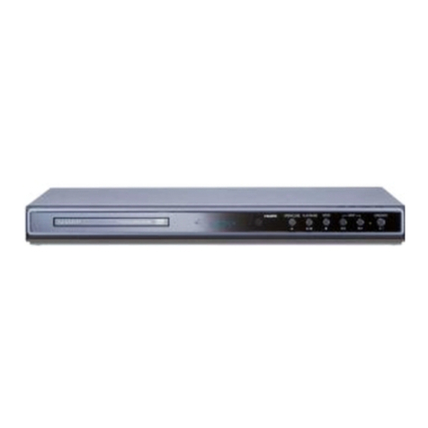
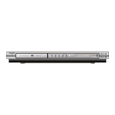
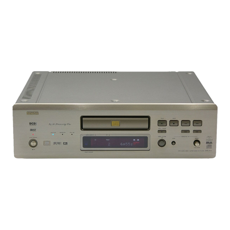
Sharp DV-SL8W User manual

DV-SL8W
1
DVD VIDEO PLAYER
Page
SPECIFICATIONS..................................................................................................................................................................2
LASER BEAM SAFETY PRECAUTIONS ..............................................................................................................................3
IMPORTANT SAFEGUARDS AND PRECAUTIONS.............................................................................................................4
STANDARD NOTES FOR SERVICING.................................................................................................................................5
OPERATING CONTROLS AND FUNCTIONS.......................................................................................................................9
TROUBLESHOOTING..........................................................................................................................................................11
BLOCK DIAGRAMS..............................................................................................................................................................16
SCHEMATIC DIAGRAMS / IC’S PIN VOLTAGE...................................................................................................................18
WAVEFORMS.......................................................................................................................................................................32
WIRING DIAGRAM...............................................................................................................................................................34
SYSTEM CONTROL TIMING CHARTS................................................................................................................................41
IC PIN FUNCTION DESCRIPTIONS....................................................................................................................................42
FL DISPLAY..........................................................................................................................................................................57
LEAD IDENTIFICATIONS.....................................................................................................................................................59
PART GUIDE
SERVICE MANUAL
No. XXXXXXXXXXXXX
SHARP CORPORATION
CONTENTS
This document has been published to be used for
after sales service only.
The contents are subject to change without notice.
DV-SL8W
MODEL
• In the interests of user-safety (Required by safety regula-
tions in some countries) the set should be restored to its
original condition and only parts identical to those specified
be used.
REMOTE
SENSOR
PLAY
–SKIP –
STOP
POWER
OFFON
OPEN/CLOSE
DVDPLAYERDV-SL8
12
MIC
VOL
D
SVCD
PBC
ALL
5
46
OPEN/
CLOSE
SETUP
OSD STEP SOUND
DIGEST SLOWMUTE
PAL/NTSC
RANDOM
AUDIOPROG
VOLUME
SUBTITLE
ANGLE
I/P SCAN
RESUME
DIRECT
TITLE
MENU/PBC
A-B
REPEAT
ZOOM
E
C
H
O
(–)
E
C
H
O
(+)
DVDVIDEOPLAYER
92L40TSL8W9003
3
2
1
789
0
+10
ENTER

DV-SL8W
2
SPECIFICATION
ITEM CONDITIONS UNIT NOMINAL LIMIT
1. Video Output 75 Vpp 1.0 ± 0.1
2-1. Coxial Digital Out mVpp 500
3. Audio (PCM)
3-1. Output Level 1 kHz 0dB Vrm 2.0
3-2. S/N ratio dB >65
3-3. Freq. Response
DVD fs=48 kHz 20 ~ 22 kHz dB ± 0.5
CD fs=44.1 kHz 20 ~ 22 kHz dB ± 0.5
3-4. THD + N
DVD 1 kHz 0dB % 0.1
CD 1 kHz 0dB % 0.1
4. Power consumption 12 W (Standby: 1.5 W)
5. Weight 1.95 kg
6. Dimension 360 mm x 38 mm x 230 mm
NOTES: 1. All Items are measured without pre-emphasis unless otherwise specified.
2. Power supply : AC110 - 240 V ~ 50/60Hz
3. Load imp. : 100 k ohm
4. Room ambient : 5°C ~ 40°C

DV-SL8W
3
LASER BEAM SAFETY PRECAUTIONS
This DVD player uses a pickup that emits a laser beam.
The laser beam is emitted from the location shown in the figure. When checking the laser diode, be sure to keep your eyes at least
30cm away from the pickup lens when the diode is turned on. Do not look directly at the laser beam.
Caution: Use of controls and adjustments, or doing procedures other than those specified herein, may result in hazardous radiation
exposure.
Do not look directly at the laser beam coming
from the pickup or allow it to strike against
your skin.
Drive Mecha Assembly
Laser Beam Radiation
Laser Pickup
Turntable

DV-SL8W
4
IMPORTANT SAFEGUARDS AND PRECAUTIONS
1. IMPORTANT SERVICE NOTES
1. NOTES DE SERVICE IMPORTANTES
SSVM
AC SCALE
1.5k ohms.
10W
0.15
TEST PROBE
TO EXPOSED
METAL PARTS
CONNECT TO
KNOWN EARTH
GROUND
CONNECT TO
KNOWN EARTH
GROUND
F
VTVM
AC SCALE
1.5k ohms
10W
TO EXPOSED
METAL PARTS
TEST PROBE
0.15 F
BEFORE RETURNING THE DVD VIDEO PLAYER
Before returning the DVD video player to the user,
perform the following safety checks.
1. Inspect all lead dress to make certain that leads are
not pinched or that hardware is not lodged between
the chassis and other metal parts in the DVD video
player.
2. Inspect all protective devices such as non-metallic
control knobs, insulation materials, cabinet backs,
adjustment and compartment covers or shields,
isola-tion resistor/capacitor networks, mechanical
insula-tors etc.
3. To be sure that no shock hazard exists, check for
current in the following manner.
●Plug the AC line cord directly into a 230 volt AC outlet
(Do not use an isolation transformer for this test).
●Using two clip leads, connect a 1.5k ohm, 10 watt
resistor paralleled by a 0.15µF capacitor in series with
all exposed metal cabinet parts and a known earth
ground, such as a water pipe or conduit.
●Use an DVM or VOM with 1000 ohm per volt, or higher,
sensitivity or measure the AC voltage drop across the
resistor (See Diagram).
●Move the resistor connection to earth exposed metal
part having a return path to the chassis (metal cabinet,
screw heads, knobs and control shafts, etc.) and
measure the AC voltage drop across the resistor.
Reverse the AC plug on the set and repeat AC voltage
measurements for each exposed part. Any reading of
1.4V rms (this corresponds to 0.7mA rms AC.) or more
is excessive and indicates a potential shock hazard
which must be corrected before returning the DVD
video player to the owner.
AVANT DE RENDRE LE REPRODUCTOR DE VÍDEO
DVD
Avant de rendre le reproductor de vídeo DVD à l'utilisateur,
effectuer les vérifications de sécurité suivantes.
1. Vérifier toutes les gaines de fil pour être sûr que les fils
ne sont pas pincés ou que le matériel n'est pas coincé
entre le châssis et les autres pièces métalliques dans le
reproductor de vídeo DVD.
2. Vérifier tous les dispositifs de protection tels que les
boutons de commande non métalliques, les matériaux
d'isolement, le dos du coffret, les couvercles de
compartiment et ajustement ou les boucliers, les
réseaux de résistance / condensateur d'isolement, Ies
isolateurs mécaniques, etc.
3. Pour être sûr qu'il n'y a aucun risque de choc électrique,
vérifier le courant de fuite de la maniére suivante.
●Brancher le cordon d'alimentation secteur directement
dans une prise de courant de 230 volts. (Ne pas utiliser
de transformateur d'isolement pour cet essai).
●Utiliser deux fils à pinces et connecter une résistance de
10 watts 1,5 kohm en parallèle avec un condensateur
de 0,15 F en série avec des pièces du coffret métallique
exposées et une masse de terre connue telle qu'un
tuyau ou un conduit d'eau.
●Utiliser un DVM ou VOM avec une sensibilité de 1000
ohms par volt ou plus ou mesurer la chute de tension
CA entre la résistance (voir diagramme).
●Déposer la connexion de la résistance à toutes les de
pièces métalliques exposées ayant un parcours de
retour au châssis (coffret métallique, tétes de vis,
boutons et arbres de commande, etc.) et mesurer la
chute de tension CA entre la résistance. Inverser la
fiche CA (une fiche intermédiaire non polarisée doit être
utilisée à seule fin de faire ces vérifications.) sur
l’appareil et répéter les mesures de tension CA pour
chaque piéce métallique exposée. Toute lecture de 1,4
V rms (ceci correspond à 0,7 mA rms CA) ou plus est
excessive et signale un danger de choc qui doit être
corrigé avant de rendre le reproductor de vídeo DVD à
son utilisateur.
DV-SL8W
5
STANDARD NOTES FOR SERVICING
Circuit Board Indications
a. The output pin of the 3 pin Regulator ICs is indicated
as shown.
Top View
Out In
Bottom View
Input
b. For other ICs, pin 1 and every fifth pin are indicated
as shown.
5
10
Pin 1
< Bottom View >
c. The 1st pin of every male connector is indicated as
shown.
Pin 1
< Bottom View >
Instructions for Connectors
1. When you connect or disconnect the FFC (Flexible
Foil Connector) cable, be sure to first disconnect the
AC cord.
2. FFC (Flexible Foil Connector) cable should be in-
serted parallel into the connector, not at an angle.
FFC Cable
Connector
CBA
* Be careful to avoid a short circuit.
Using lead-free wire solder
When fixing the PWB soldered with the lead-free solder,
apply lead-free wire solder. Repairing with conventional
lead wire solder may cause damage or accident due to
cracks.
As the melting point of lead-free solder (Sn-Ag-Cu) is
higher than the lead wire solder by 40°C, we recommend
you to use a dedicated soldering bit, if you are not
familiar with how to obtain lead-free wire solder or
soldening bit, contact our service station or service
ranch in your area.
Soldering
As the melting point of lead-free solder (Sn-Ag-Cu) is
about 220°C which is higher than the conventional lead
solder by 40°C, and as it has poor solder wettabillty, you
may be apt to keep the soldering bit in contact with the
PWB for extended period of time. However, Since the
land may be peeled off or the maximum heat-resistance
temperature of parts may be excoeded, remove the bit
from the PWB as soon as you conurm the steady
soldering condition.
Lead-free solder contains more tin, and the end of the
soldering bit may be easily corroded. Make sure to tum
on and off the power of the bit as required. if a different
type of solder stays on the tip of the soldering bit, it is
alloyed with lead-free solder. Clean the bit after every
use of it.
When the tip of the soldering bit is blackened during
use, file it with steel wool or fine sandpaper.
Becareful when replacing parts with polarity indication
on the PWB silk.
Lead-free wire solder for servicing
Part No. Description Code
ZHNDAi123250E J 0.3mm 250g(1roll) BL
ZHNDAi126500E J 0.6mm 500g(1roll) BK
ZHNDAi12801KE J 1.0mm 1kg(1roll) BM

DV-SL8W
6
How to Remove / Install Flat Pack-IC
1. Removal
With Hot-Air Flat Pack-IC Desoldering Machine:
(1) Prepare the hot-air flat pack-IC desoldering ma-
chine, then apply hot air to the Flat Pack-IC (about 5
to 6 seconds). (Fig. S-1-1)
Fig. S-1-1
(2) Remove the flat pack-IC with tweezers while apply-
ing the hot air.
(3) Bottom of the flat pack-IC is fixed with glue to the
CBA; when removing entire flat pack-IC, first apply
soldering iron to center of the flat pack-IC and heat
up. Then remove (glue will be melted). (Fig. S-1-6)
(4) Release the flat pack-IC from the CBA using twee-
zers. (Fig. S-1-6)
Caution:
1. Do not supply hot air to the chip parts around the flat
pack-IC for over 6 seconds because damage to the
chip parts may occur. Put masking tape around the
flat pack-IC to protect other parts from damage.
(Fig. S-1-2)
2. The flat pack-IC on the CBA is affixed with glue, so
be careful not to break or damage the foil of each pin
or the solder lands under the IC when removing it.
Hot-air
Flat Pack-IC
Desoldering
Machine
CBA
Flat Pack-IC
Tweezers
Masking
Tape
Fig. S-1-2
With Soldering Iron:
(1) Using desoldering braid, remove the solder from all
pins of the flat pack-IC. When you use solder flux
which is applied to all pins of the flat pack-IC, you can
remove it easily. (Fig. S-1-3)
Flat Pack-IC Desoldering Braid
Soldering Iron
Fig. S-1-3
(2) Lift each lead of the flat pack-IC upward one by one,
using a sharp pin or wire to which solder will not
adhere (iron wire). When heating the pins, use a fine
tip soldering iron or a hot air desoldering machine.
(Fig. S-1-4)
Fine Tip
Soldering Iron
Sharp
Pin
Fig. S-1-4
(3) Bottom of the flat pack-IC is fixed with glue to the
CBA; when removing entire flat pack-IC, first apply
soldering iron to center of the flat pack-IC and heat
up. Then remove (glue will be melted). (Fig. S-1-6)
(4) Release the flat pack-IC from the CBA using twee-
zers. (Fig. S-1-6)
With Iron Wire:
(1) Using desoldering braid, remove the solder from all
pins of the flat pack-IC. When you use solder flux
which is applied to all pins of the flat pack-IC, you can
remove it easily. (Fig. S-1-3)
(2) Affix the wire to a workbench or solid mounting point,
as shown in Fig. S-1-5.
(3) While heating the pins using a fine tip soldering iron
or hot air blower, pull up the wire as the solder melts
so as to lift the IC leads from the CBA contact pads
as shown in Fig. S-1-5.

DV-SL8W
7
(4) Bottom of the flat pack-IC is fixed with glue to the
CBA; when removing entire flat pack-IC, first apply
soldering iron to center of the flat pack-IC and heat
up. Then remove (glue will be melted). (Fig. S-1-6)
(5) Release the flat pack-IC from the CBA using twee-
zers. (Fig. S-1-6)
Note:
When using a soldering iron, care must be taken to
ensure that the flat pack-IC is not being held by glue.
When the flat pack-IC is removed from the CBA,
handle it gently because it may be damaged if force
is applied.
To Solid
Mounting Point
Soldering Iron
Iron Wire
or
Hot Air Blower
Fig. S-1-5
Fine Tip
Soldeing Iron
CBA
Flat Pack-IC
Tweezers
Fig. S-1-6
2. Installation
(1) Using desoldering braid, remove the solder from the
foil of each pin of the flat pack-IC on the CBA so you
can install a replacement flat pack-IC more easily.
(2) The "●" mark on the flat pack-IC indicates pin 1. (See
Fig. S-1-7.) Be sure this mark matches the 1 on the
PCB when positioning for installation. Then presol-
der the four corners of the flat pack-IC. (See Fig. S-
1-8.)
(3) Solder all pins of the flat pack-IC. Be sure that none
of the pins have solder bridges.
Example :
Pin 1 of the Flat Pack-IC
is indicated by a " " mark. Fig. S-1-7
Presolder
CBA
Flat Pack-IC
Fig. S-1-8

DV-SL8W
8
Instructions for Handling
Semi-conductors
Electrostatic breakdown of the semi-conductors may
occur due to a potential difference caused by electrostatic
charge during unpacking or repair work.
1. Ground for Human Body
Be sure to wear a grounding band (1MΩ) that is properly
grounded to remove any static electricity that may be
charged on the body.
2. Ground for Workbench
Be sure to place a conductive sheet or copper plate with
proper grounding (1MΩ) on the workbench or other
surface, where the semi-conductors are to be placed.
Because the static electricity charge on clothing will not
escape through the body grounding band, be careful to
avoid contacting semi-conductors with your clothing.
CBA
< Incorrect >
CBA
Grounding Band
Conductive Sheet or
Copper Plate
< Correct >

DV-SL8W
9
OPERATING CONTROLS AND FUNCTIONS
■Main unit (front panel)
■Main unit (rear panel)
REMOTE
SENSOR
PLAY
– SKIP –
STOP
POWER
OFF ON
OPEN/CLOSE
DVD PLAYER DV-SL8
12
MIC
VOL
D
SVCD
PBC
ALL
The rating label is located
on the bottom of the unit.
Manufactured under license from Dolby Laboratories.
"Dolby" and the double-D symbol are trademarks
of Dolby Laboratories.
RL
P
B
YP
R
Apparatus Claims of U.S. Patent Nos. 4,631,603;
4,577,216; 4,819,098; 4,907,093; and 6,516,132
licensed for limited viewing uses only.
"DTS" and "DTS Digital Out" are trademarks of
Digital Theater System, Inc.
COMPONENT
VIDEO OUT
AUDIO
OUT
AC INPUT VIDEO
OUT
S-VIDEO
OUT
DIGITAL
OUT (COAXIAL)
3
6
6
5
5
910
78 3
1
4 2
4 2
1
3
1) Power Button
2) Microphone Volume Controls
3) Microphone Sockets
4) Stop Button
5) Play or Pause Button
6) Chapter (track) Skip up
7) Chapter (track) Skip Down
8) Remote Sensor
9) Disc Tray Open/Close Button
10) Disc Tray
1) Video Output Socket
2) S-Video Output Socket
3) Component Video Output Sockets
4) Digital Output Socket (Coaxial)
5) Audio Output Socket
6) AC Cord Lead

DV-SL8W
10
546
OPEN/
CLOSE
SETUP
OSD STEP SOUND
DIGEST SLOW MUTE
PAL/NTSC
RANDOM
AUDIO PROG
VOLUME
TITLE
MENU/PBC
A-B
REPEAT
ZOOM
DVD VIDEO PLAYER
321
789
0
+10
ENTER
SUBTITLE
ANGLE
I/ P-SCAN
RESUME
DIRECT
E
C
H
O
(–)
E
C
H
O
(+)
92L40TSL8W9003
■Remote control
1. Remote Control Transmitter
2. Setup Menu Button
3. Subtitle Select Button
4. Angle Select Button
5. Interlace and Progressive Scan
6. Direct Button
7. Resume Button
8. Title Select Button
9. Zoom Button
10. Cursor or Echo Level Up and Down Buttons
11. Key Control Button (normal)
12. Key Control Button (lower)
13. Fast Forward
14. Fast Backward
15. Step Button (Frame by frame advance Playback)
16. On screen Display on/off Button
17. Video CD Digest Button
18. Slow Button
19. PAL/NTSC Select Button
20. Disc Tray Open/ Close Button
21. Direct Number Buttons
22. Menu/ Playback Control On/ Off Button
23. A-B Repeat Button
24. Repeat Play Button
25. Enter Button
26. Play or Pause Button
27. Key control Button (highest)
28. Stop Button
29. Chapter (track) Skip Up
30. Chapter (track) Skip Down
31. Sound Button
32. Mute Button
33. Volume Up and Down Button
34. Programme Button
35. Audio Select Button
36. Random Button
2
1
3
4
5
6
7
8
9
10
11
12
13
14
15
16
17
18
19
20
21
22
23
24
25
26
27
28
29
30
31
32
33
34
35
36

DV-SL8W
11
TROUBLESHOOTING
FLOW CHART NO. 2
The fuse blows out.
After servicing, replace the fuse.
FLOW CHART NO. 3
When the output voltage fluctuates.
Yes
No
FLOW CHART NO. 4
FLOW CHART NO. 5
-21V is not outputted.
Yes
No
FLOW CHART NO. 1
The power cannot be turned on.
Is the fuse normal?
Yes
Yes
Yes
No
No
No
Is normal state restored when once unplugged power
cord is plugged again after several seconds? Check if there is any leak or short-circuiting on the
primary circuit component, and service it if defective.
(IC1, B1, C1, C2, E1, RT, D1, D2, D3, D4, C3, C9)
Check the presence that the rectifying diode or circuit
is shorted in each rectifying circuit of secondary side,
and service it if defective.
Check IC2, IC3 and their periphery, and service it if
defective.
Check D8 and periphery circuit, and service it if
defective.
See FLOW CHART No. 2 <The fuse blows out.>
Check each rectifying circuit of the secondary circuit
and service it if defective.
Check the presence that the primary component is
leaking or shorted and service it if defective.
Check IC1, E2, D6 and their periphery, and service it if
defective.
Is approximately -21V voltage supplied to the anode of
D8?
Check if there is any leak or short-circuit on the loaded
circuit, and service it if defective.
Check if there is any short-circuit on the rectifying diode and the circuit in each rectifying circuit of the secondary side
, and
service it if defective.
(D7, D8, D9, D10, DW1, DW2, E3, E4, E7, E10)
Does the photo coupler circuit on the secondary side
operate normally?
When buzz sound can be heard in the vicinity of power circuit.
Is the D +5V line voltage normal?

DV-SL8W
12
FLOW CHART NO. 7
FLOW CHART NO. 6
P-ON (+12V) is not outputted.
FLOW CHART NO. 8
The key operation is not functioning.
Yes
No
Check E7, E8 and the periphery circuit, and service it
if defective.
The fluorescent display tube does not light up.
Replace the fluorescent display tube.
Replace IC1 (Front panel).
Is 5V voltage supplied to Pins(14,38) of IC1 (Display
PWB)?
Is the voltage of approximately -21V supplied to
Pin(27) of IC1 (Front panel)?
Is there 500kHz oscillation at Pin(26) of IC1 (Display
PWB)?
Are the filament voltage supplied between Pins(1,2)
and Pins(29, 30) of the fluorescent display tube? And
the negative voltage applied between these pins and
GND?
Check D9, B1 and the periphery circuit, and service it
if defective.
Check the +5V line and service it if defective.
Is -16V voltage supplied to anode of D7?
Check the -21V line and service it if defective.
Check R2002, IC1 (Display PWB) and their periphery,
and service it if defective.
Check B1, and their periphery, and service it if
defective.
Check D7, E3, R12, and their periphery, and service it
if defective.
Is +12V voltage supplied to the kathode of D9?
Yes
Yes
Yes
Yes
Yes
Yes
No
No
No
Are the contact point and the installation state of the
key switches (K1, K2, K3, K4, K5) normal?
Re-install the switches (K1, K2, K3, K4, K5) correctly
or replace the poor switch.
No
When pressing each switches (K1, K2, K3, K4, K5), do
the voltage of each pin of IC1 (shown below) increase?
K1: IC1 Pin 13
K2: IC1 Pin 12
K3: IC1 Pin 11
K4/K5: IC1 Pin 10
Check the switches (K1, K2, K3, K4, K5) and their
periphery, and service it if defective.
No
No No
Yes

DV-SL8W
13
FLOW CHART NO. 10
FLOW CHART NO. 9
No operation is possible from the remote control unit.
Yes
Replace the DVD Servo PWB.
No improvement can be found.
Replace the DVD Mecha.
Yes
Is the "L" pulse supplied to the Pin("IR") of CN4?
Yes
No
Is 5V voltage supplied to Pin(3) terminal ofthe infrared
remote control receiver (RE1)?
Is the "L" pulse sent out Pin(1) terminal of receiver
(RE1) when the infrared remote control is activated?
The disc tray cannot be opened and closed. (It can be done using the remote control unit.)
Is the normal control voltage inputted to Pin(10) of IC1?
Refer to "FLOW CHART NO.12" <The key operation is
not functioning.>
Refer to "FLOW CHART NO.15" <The disc tray cannot
be opened and closed.>
Check EV+5V line and service it if defective.
No Replace the infrared remote control receiver (RE1).
Or replace the remote control unit.
No Check the line between Pin(1) terminal of receiver
(RE1) and Pin("IR") of CN4, and service it if defective.
Replace the "OPEN/CLOSE" button K5 (S5).
Operation is possible from the DVD, but no operation
is possible from the remote control unit.
FLOW CHART NO. 11
The disc tray cannot be opened and closed.
Yes
Yes
No
Original DVD Servo PWB is poor.
No
Replace the DVD Servo PWB.
No improvement can be found.
Replace the DVD Mecha.
FLOW CHART NO. 12
[No Disc] indicated. (When the focus error occurs.)
Yes
Original DVD Servo PWB is poor.
No

DV-SL8W
14
Replace the DVD Servo PWB.
No improvement can be found.
Replace the DVD Mecha.
FLOW CHART NO. 13
[No Disc] indicated. (When the focus servo is not functioning.)
Yes
Original DVD Servo PWB is poor.
No
Replace the DVD Servo PWB.
No improvement can be found.
Replace the DVD Mecha.
FLOW CHART NO. 14
[No Disc] indicated. (When the laser beam does not light up.)
Yes
Original DVD Servo PWB is poor.
No
Replace the DVD Servo PWB.
No improvement can be found.
Replace the DVD Mecha.
FLOW CHART NO. 15
Both functions of picture and sound do not operate normally.
Yes
Yes
Original DVD Servo PWB is poor.
No
Check the line between Q12, Q13, Q14, Q15, Q16,
Q25 and each pin of U13, and service it if defective.
Are the video signals outputted to each pin of below:
L21: Cr/Pr, (WF8+WF9)
L20: Cb/Pb, (WF6+WF7)
L18: S-Y, (WF2)
L16: S-C (WF3)
L19: Component Y (WF4+WF5)
L15: Video Out (WF1)
Check the line between L15, L16, L18, L19, L20, L21
and S-Video (J3), AV (J4) output terminal, and service
it if defective.
No
Set the disc on the disc tray, and playback.
FLOW CHART NO. 16
Picture does not appear normally.

DV-SL8W
15
Set the disc on the disc tray, and playback.
FLOW CHART NO. 17
Audio is not outputted normally.
Check each line between IC U20 and IC U13 or
replace IC U20 or DVD MPEG PWB or DVD Mecha.
Are the analog audio signal outputted from each pin of
IC U20?
IC U20, Pin 5: Audio-R;
IC U20, Pin 8: Audio-L;
No
Check each line between IC U2 and IC U20 or Vcc
line supply to IC U2.
Are the analog audio signal inputted from each pin of
IC U2?
IC U2, Pin 2: Audio-R;
IC U2, Pin 6: Audio-L;
No
Yes
Replace IC U2.Are the analog audio signal outputted from each pin of
IC U2?
IC U2, Pin 1: Audio-R;
IC U2, Pin 7: Audio-L;
No
Yes
Check the periphery between Pin(1,7) of IC U2 and
Audio terminal J4, and service it if defective.
Are the audio signal outputted to the specific output
terminals?
Are the audio signal outputted to the audio terminal
(J4)?
No
Yes

DV-SL8W
16
BLOCK DIAGRAMS
A
B
C
D
E
10 9 8 7 6

DV-SL8W
17
54 321

DV-SL8W
18
SCHEMATIC DIAGRAMS / IC’S PIN VOLTAGE
Standard Notes
WARNING
Many electrical and mechanical parts in this chassis
have special characteristics. These characteristics often
pass unnoticed and the protection afforded by them
cannot necessarily be obtained by using replacement
components rated for higher voltage, wattage, etc.
Replacement parts that have these special safety
characteristics are identified in this manual and its
supplements; electrical components having such
features are identified by the mark " " in the schematic
diagram and the parts list. Before replacing any of these
components, read the parts list in this manual carefully.
The use of substitute replacement parts that do not
have the same safety characteristics as specified in the
parts list may create shock, fire, or other hazards.
Capacitor Temperature Markings
Mark Capacity
change rate
Standard
temperature
Temperature
range
(B)
(F)
±10%
+30 - 80%
±15%
+30 - 80%
20°C
20°C
20°C
20°C
-25~+85°C
-25~+85°C
-25~+85°C
-10~+70°C
(SR)
(Z)
Capacitors and transistors are represented by the
following symbols.
Notes:
1. Do not use the part number shown on these draw-
ings for ordering. The correct part number is shown
in the parts list, and may be slightly different or
amended since these drawings were prepared.
2. All resistance values are indicated in ohms (K=103,
M=106).
3. Resistor wattages are 1/4W or 1/6W unless other-
wise specified.
4. All capacitance values are indicated in µF
(P=10-6 µF).
5. All voltages are DC voltages unless otherwise speci-
fied.
6. Electrical parts such as capacitors, connectors, di-
odes, IC's, transistors, resistors, switches, and fuses
are identified by four digits. The first two digits are
not shown for each component. In each block of the
diagram, there is a note such as shown below to
indicate these abbreviated two digits.
(Top View) (Bottom View)
Electrolytic Capacitor
+
CBA Symbols
Transistor Transistor
(Top View)
ECB
(Top View)
ECB

DV-SL8W
19
LIST OF CAUTION, NOTES, AND SYMBOLS USED IN THE SCHEMATIC DIAGRAMS ON THE
FOLLOWING PAGES:
1.CAUTION:
FOR CONTINUED PROTECTION AGAINST FIRE HAZARD, REPLACE ONLY WITH THE SAME TYPE
FUSE.
2.CAUTION:
Fixed Voltage (or Auto voltage selectable) power supply circuit is used in this unit.
If Main Fuse (F1001) is blown, first check to see that all components in the power supply circuit are not defective
before you connect the AC plug to the AC power supply. Otherwise it may cause some components in the power
supply circuit to fail.
3.Note:
(1)Do not use the part number shown on the drawings for ordering. The correct part number is shown in the parts list,
and may be slightly different or amended since the drawings were prepared.
(2)To maintain original function and reliability of repaired units, use only original replacement parts which are listed
with their part numbers in the parts list section of the service manual.

DV-SL8W
20
Figure 1 SERVO SCHEMATIC DIAGRAM (1/8)
A
B
C
D
E
F
G
H
123457
GND
A+5V
M+5V
DVCC
AGND
AVCC12
VPLLVCC1 .8VCC 1.8
V+5V
DVCC3
P+5V
GND
P+12V
GND
P+5V
P-12V
GND
GND
GND
GND
P+12V
GND
GND
GND
GND
GND GND
GND
MOTOR +5V
power
SYSTEM +5V power
Servo analog +5V
power
250mA
8200
kernell
+1.9V
Video PLL
power +1.8V
Video buffer +5V
R97
390
BC42
0.1U
L22
BC16
0.1u
FB4
FB(300ma 0.7 ohm)
BC36
0.1U
BC94
EC38
220U16V
BC84
0.1U
BC28
0.1U
L23
FB(300ma 0.7 ohm)
FB(300ma 0.7 ohm)
R183
33
BC86
0.1U
BC95
0.1U 0.1U 0.1U
L36
FB(300ma 0.7 ohm)
R152
2.2
BC75
0.1U
0.1U
EC34
100U16V
CN18
CON6-2.54
1
2
3
4
5
6
BC42
0.1U
+
EC26
220U10V
EC27
220U16V
BC68
BC94
0.1U
BC46
0.1U
EC28
220U16V
D4
1N4001
U8 LD1117(TO-252 1A)
ADJ
1
IN
3OUT 2
U9 LD1 117-3V3(1A)
ADJ
1
IN
3OUT 2
R183 100
R96
200
BC45
R71 10
Table of contents
Other Sharp DVD Player manuals

Sharp
Sharp DV-NC65H User manual

Sharp
Sharp DV-S11S(G) User manual

Sharp
Sharp DV-760X User manual

Sharp
Sharp DV-SL10H User manual

Sharp
Sharp DV-AT4000 User manual

Sharp
Sharp DV-SV97H User manual

Sharp
Sharp DV-SL90UM User manual

Sharp
Sharp DV-SL10 User manual

Sharp
Sharp DV-S1 User manual

Sharp
Sharp DV-SL800W User manual

Sharp
Sharp DV-S1U User manual

Sharp
Sharp DV-SV90S(B) User manual

Sharp
Sharp DV-SL1500W User manual

Sharp
Sharp DV-SV90S(Y) User manual

Sharp
Sharp DV-SV97S(S) User manual

Sharp
Sharp DV-S1X User manual

Sharp
Sharp DV-740/T User manual

Sharp
Sharp DV-560H User manual

Sharp
Sharp DV-620S User manual

Sharp
Sharp DV-NC100X User manual