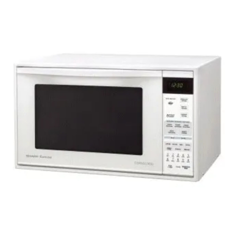
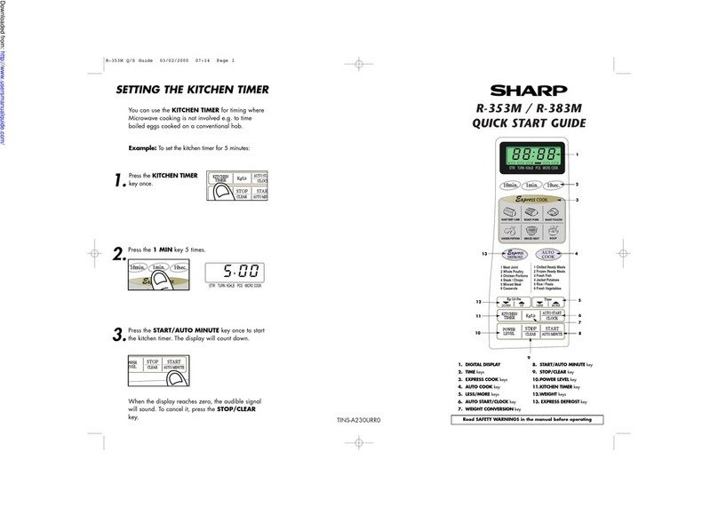
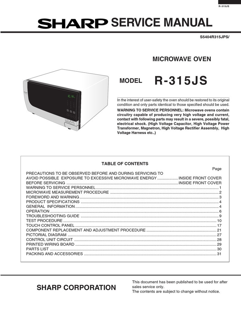
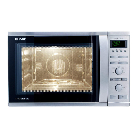
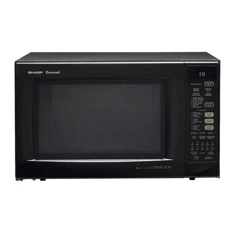
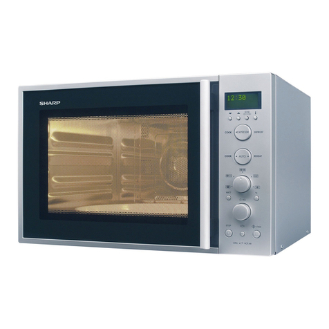
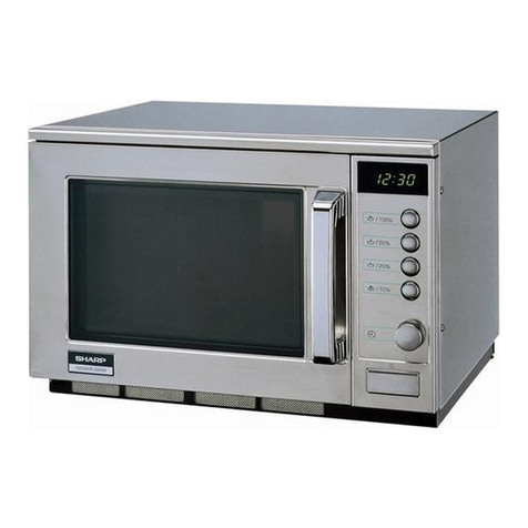
Sharp R-9200 User manual

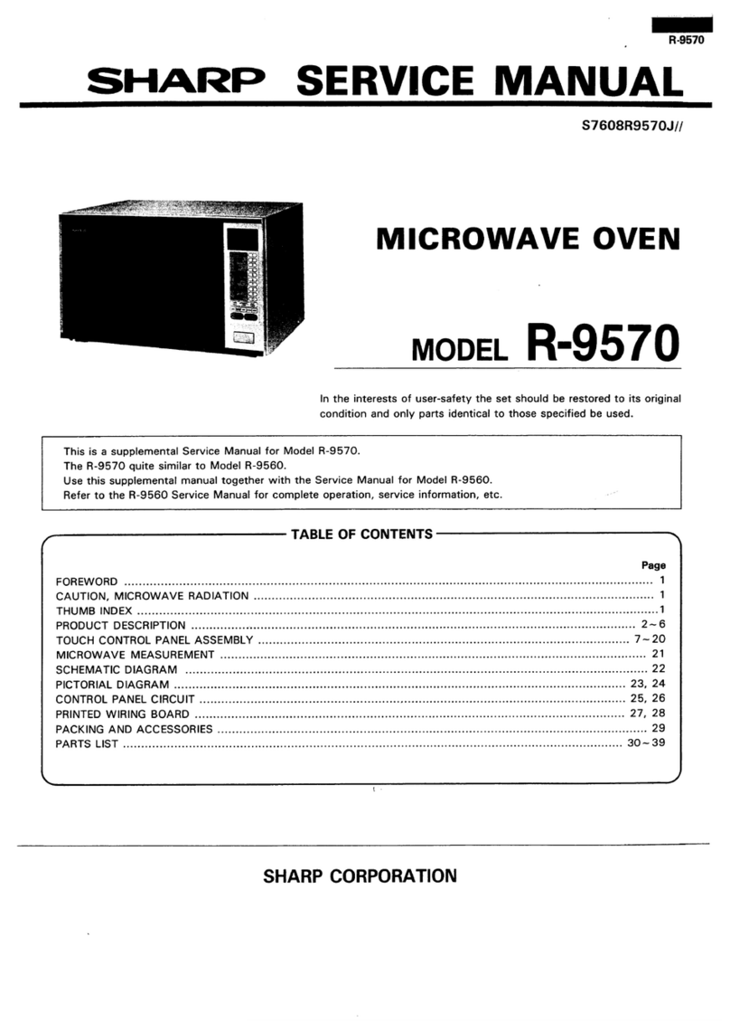
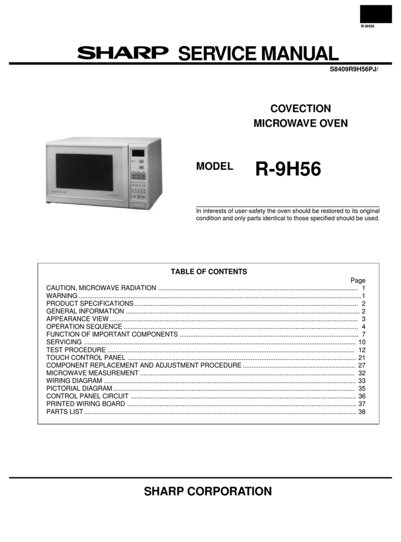
SHARP SERVICE MANUAL .
S3201 RSZOOJ//
CONVECTION
MICROWAVE OVEN
MODEL R-9200
In interests of user-safety the oven should be restored to its original
condition and only manufacturer original spare parts must be used.
(RD161OlU)
This is a supplemental Service Manual for Model R-9ZOO.
This model is quite similar to Base Model R-9HlO (Refer No. is S9808R9HlOJ//).
Use this supplemental manual together with the Base Model Service Manual.
Refer to the Base Model Service Manual for complete operation, service information, etc. (RD17101U)
TABLE OF CONTENTS Page
APPEARANCE VIEW ........................................................................................................... Inside front cover
GENERAL IMPORTANT INFORMATION ...................................................................................................... 1
CAUTION, MICROWAVE RADlATlON,WARNING ...................................................................................... 1
PRODUCT SPECIFICATIONS ......................................................................................................................... 2
OPERATION ....................................................................................................................................................... 3
FUNCTION OF IMPORTANT COMPONENTS .............................................................................................. 4
SERVICING ........................................................................................................................................................ 5
TEST PROCEDURE ........................................................................................................................................... 6
TOUCH CONTROL ASSEMBLY .................................................................................................................. 13
COMPONENT REPLACEMENT AND ADJUSTMENT PROCEDURE ..................................................... 21
MICROWAVE MEASUREMENT ................................................................................................................... 22
WIRING DIAGRAM ....................................................................................................................................... 23
PICTORIAL DIAGRAM .................................................................................................................................. 25
CONTROL PANEL CIRCUIT ......................................................................................................................... 26
PRINTED WIRING DIAGRAM ..................................................................................................................... 27
PARTS LIST .................................................................................................................................................... 28
SHARP CORPORATION *

Touch Control Panel
-43
1. Ventilation openings
2. Oven lamp
3. Hinges
4. Safety door latches
5. See through door
6. Door open button
7. Touch Control Panel
8. Digital readout
9. Waveguide cover
lO.Access cover for oven
lamp replacement
ll.Menue Label for Intelli-
gent Sensor
12.Low rack
13.High rack
14.Defrost rack
Convection I CONV AUTOCOOK+j
Fan Symbol
Micro/Defrost
Symbol
MIX SENSORDEFROSTTEMP
Indicator
WEIGHT ADJUST PAD
Press to zero the
your own dishes
INTELLIGENT SENSOR PAD
Press to select 12 popular Mix,
Grill and Micro cooking menu
with weight sensor or AH sensor.
cooking with weight sensor.
with weight sensor.
NUMBER AND TEMPERATURE-
PADS
Press to enter cooking times,
clock time, convection tem-
perature or to select the
Intelligent Sensor menus.
POWER LEVEL PADS
Pressto select microwave
power setting.
If not pressed, HIGH is auto-
matically selected.
STOP/CLEAR PAD
Press to erase during pro-
gramming.
Press once to stop operation
of oven during cooking; press
twice to cancel cooking pro-
gramme.
AUTO
I START/CLOCK PAD
Press to set clock or Auto
Start time.
*SENSOR INSTANT ACTION
PADS
Press once to cook 8 popular
menus.
CONVECTION COOKIN
FUNCTION PADS
Press to cook for each tunc-
tion.
*MORE, LESS PADS
Press to increase/decrease the
time in one minute increments
during cooking or to alter the
doneness for the Sensor Instant
Action, Intelligent Sensor or
Defrost Sensor modes.
IrlNSTANT COOK/START PAD
I Press once to cook for 1 minute
STOP START INSTANT COOK, - at HIGH or increase by 1 minute
CLEAR CLOCK START multiples each time this pad is
\ I
I / pressed during Microwave,
Convection, Grill or Mix cooking.

SERVICE MANUAL
SHARI=
CONVECTION MICROWAVE OVEN
R-9200
GENERAL IMPORTANT INFORMATION
This Manual has been prepared to provide Sharp Corp. Service
engineers with Operation and Service Information.
It is recommended that service engineers carefully study the
entire text of this manual and base model manual, so they will
be qualified to render satisfactory customer service.
r- (RD36106
CAUTION
MICROWAVE RADIATION
Service engineers should not be exposed to the micro-
wave energy which may radiate from the magnetron or
other microwave generating devices if it is improperly
used or connected. All input and output microwave
connections, waveguides, flanges and gaskets must be
secured. Never operate the device without a microwave
energy absorbing load attached. Never look into an
open waveguide or antenna while the device is ener-
gized. (RD36203U)
WARNING
Never operate the oven until the following points are
ensured.
(A)The door is tightly closed.
(B) The door brackets and hinges are not defective.
(C)The door packing is not damaged.
(D)The door is not deformed or warped.
(E) There is not any other visible damage with the oven.
Servicing and repair work must be carried out only by
trained service engineers.
All the parts marked “+‘I on parts list are used at voltages
more than 250V.
(RD5111 Ou)
SHARP CORPORATION
OSAKA, JAPAN
R-9ZOO
““?j PRODUCT DESCRIPTION
\ :‘:;j OPERATING SEQUENCE
- :;--;:;sj
“-”“+$j FUNCTION OF IMPORTANT
COMPONENTS
it< 2 ”
-*: i
-, “, .’ j
I< ” “,
I “s TEST PROCEDURE
x
*
i : ”f*
” *“>*
^rt ‘*a$
I^*
‘f TOUCH CONTROL PANEL
_I
8~~9 ASSEMBLY
COMPONENTS
REPLACEMENT AND
ADJUSTMENT PROCEDURE
” “*
:<
* -2. MICROWAVE MEASUREMENT
WIRING DIAGRAM
i
s.
‘.
PARTS LIST
(RD37201 U)

R-9ZOO
PRODUCT DESCRIPTION
SPECIFICATIONS
ITEM
Power Requirements 240 Volts
50 Hertz
DESCRIPTION
Power Consumption
Power Output
Convection Heating element
Case Dimensions
Single phase, 3 wire earthed
16OOW (Microwave)
1600W (Convection)
800 watts nominal of RF microwave energy (2 litre water load)
900 watts (I EC-705-1 988)
Operating frequency of 2450M Hz
1500 w
Width 627 mm
Height 378 mm
Depth 481 mm
Cooking Cavity Dimensions Width 410 mm
Height 245 mm
Depth 410 mm
Control Complement Touch Control System
Clock( I:00 - 12:59 )
Timer (0 - 99 min. 99 sec. )
Microwave Power for Variable Cooking
Repetition Rate;
HIGH ..*............................. Full power throughout the cooking time
MED HIGH ............................................... approx. 70% of Full Power
MED .........................................................* approx. 50% of Full Power
MED LOW (DEFROST) .......................... approx. 30% of Full Power
LOW .........*................................................ approx. 10% of Full Power
Convection Temperature for Variable Cooking
CONVECTION ............................................ 40 to 250°C Temp. control
LOW M IX( BAKE) ........................ 180°C with 10% microwave power
HIGH MIX( ROAST) m...................
GRILL 200°C with 30% microwave power
............................................................................ 250°C
INTELLIGENT SENSOR pad (preheat)
DEFROST SENSOR pad
WEIGHT ADJUST pad
INSTANT ACTION SENSOR pads
NUMBER and TEMPERATURE pads
POWER LEVEL pads
MORE. LESS pads
STOP/CLEAR pad
Set Weight .
AUTO START/CLOCK pad
1 INSTANT COOK/START pad
Approx. 31 kg
(RD44101 U)
NOTE: Numbers and letters shown after sentences such as “RD44101 U” are for factory use only.
2
--.r-.w-- -.1---- ,---- -._ _ _

R-9ZOO
OPERATING SEQUENCE
INTELLIGENT SENSOR COOKING CONDI-
TION
The oven cooks foods automatically by using the
weight sensor cooking condition or the absolute hu-
midity sensor (AH sensor) cooking condition.
Weight sensor cooking condition.
1. The oven detects the weight of food automatically
when food is placed into the oven.
2. The oven sets the cooking condition and cooking
time automatically when the food category is
inputted.
3. The oven starts cooking when the start button is
pressed.
AH sensor cooking condition
1. This is the same as Sensor cooking condition of the
base model (R-9HlO)
INSTANT ACTION SENSOR COOKING
CONDITION
This is the same as INTELLIGENT SENSOR cooking
condition. In this condition the oven starts soon when
touching INSTANT ACTION SENSOR pads.
DEFROST SENSOR CONDITION
The oven heats food automatically by using Weight
sensor cooking condition.
SENSING FIRE OPERATION
The oven will stop its operation when there is fire in
the oven cavity in microwave cooking condition.
l LSI measures the voltage across the temperature
measurement circuit intermittently within a 32 sec-
ond time base since the oven is started in micro-
wave cooking condition. The oven will stop its
operation when the difference of the voltage is more
than 0.3 volts in microwave cooking condition.
1.
2.
3.
4.
Within a 32 second base, first thermistor is ener-
gized for 3 seconds. After 2 seconds since the
thermistor is energized, the voltage across the tem-
perature measurement circuit is measured. And af-
ter 21 seconds since the thermistor is cut off, the
convection motor operates for 6 seconds.
The oven carries out the procedure above again. If
the second voltage is 0.3V higher than the first
voltage, LSI judges it is a fire in the oven cavity and
stops the oven.
When sensor cooking, the sensing fire operation is
not carried out until the oven senses the steam from
food. Because food cannot be cooked well by ro-
tating the convection fan at that time. After sensing
the steam, the sensing fire operation is started.
When LSI judges it is fire in the oven cavity, LSI
will switch off the relays to the power transformer,
fan motor and convection motor and LSI stops
counting down.
that the fresh air
ity.
Q?
i f
CONVECTION , ,
MOTOR ; I
ON ;I
And then the damper is closed so
does not come into the oven cav-
2P 3? ?2 (sec.)
t?Osec. i i
! ’ !
ii I
1 1 3 sec. I
THERMISTOR + ;tc- I I
I I
Sensing
Voltage
Sensing the voltage across temperature
measurement circuit.
3

WEIGHT SENSOR
FUNCTION OF MAIN COMPONENTS
WEIGHT SENSOR ASSEMBLY
Micr-
computer
Weight Sensor - Osilator I WI)
J-U-LI -I
1. When the food is placed on the
turntable, the gap between the
elctrodes increases in direct pro-
portional to the weight of food.
The elctrodes have the function of
a capacitor.
2. The frequency of the
oscilator changes according
to the capacitance of the
weight sensor.
3. The micro-computer meas-
ures the weight of food by
detecting the change in the
oscilating frequency.

R-9ZOO
SERVICING
WARNING TO SERVICE PERSONNEL
Microwave ovens contain circuitry capable of producing very high voltage and current, contact with any part
of the high voltage circuit will result in electrocuition.
REMEMBER TO CHECK 3D
1) Disconnect the supply.
2) Door opened, an.d wedged open.
3) Discharge high voltage capacitor.
WARNING AGAINST THE CHARGE OF THE
HIGH-VOLTAGE CAPACITOR
The high-voltage capacitor remains charged
about 60 seconds after the oven has been
switched off. Wait for 60 seconds and then
short-circuit the connection of the
high-voltage capacitor (that is, of the con-
necting lead of the high-voltage rectifier)
~against the chassis with the use of an insu-
i lated screwdriver.
Sharp recommend that wherever possible
fault-finding is carried out with the supply discon-
nected. It may in, some cases, be necessary to
connect the supply after the outer case has been
removed, in this event carry out 3D checks and then
disconnect the leads to the primary of the power
transformer. Ensure that these leads remain isolated
from other components and the oven chassis. (Use
insulation tape if necessary.) When the testing is
completed carry out 3D checks and reconnect the
leads to the primary of the power transformer.
REMEMBER TO CHECK 4R
1) Reconnect all leads removed from components
during testing.
2) Replace the outer case (cabinet).
3) Reconnect the supply.
4) Run the oven. Check all functions.
Microwave ovens should not be run empty. To test
for the presence of microwave energy within a
cavity, place a cup of cold water on the oven
turntable, close the door and set the microwave
timer for two (2) minutes. Set the power level to
HIGH and push the START button. When the two
minutes has elapsed (timer at zero) carefully check
that the water is now hot. If the water remains cold
carry out 3IJ checks and re-examine the con-
nections to the component being tested.
When all service work is completed, and the oven is fully assembled, the microwave power output should
be checked and a microwave leakage test carried out.
TROUBLESHOOTINGGUIDE
When troubleshooting the microwave oven, it is helpful
to follow the Sequence of Operation in performing the
checks. Many of the possible causes of trouble will
require that a specific test be performed. These tests
are given a procedure letter which will be found in the
“Test Procedure”section.
IMPORTANT: If the oven becomes inoperative be-
cause of a blown fuse M8A in the up-
per latch switch - lower latch switch -
monitor switch - monitor resistor cir-
cuit, check the upper latch switch,
lower latch switch, monitor switch and
monitor resistor before replacing the
fuse M8A.
5
A
-
E
NG
;
i
-
-
-
--
-
-
I
7
J
i-
-
E
ii
z
ii
is
ki
ii
R
-
-
-
-
-
-
j7
c
-
iz
!s
$
E
ii
2
M
i
-
-
-
-
-
-
-
-
I
1
T
;iJ
Es
&T
P
6s
ii
L2
G
ki
3
1
7
-
F
p:
:
i
:
H
-
-
V
-
-
-
-
-
-
-
-
t
3
T
0
E
-
H
i7
.
ii
ii
I
OT
R
-
-
-
-
-
-
-
-
-
-
-
-
I
z
-
i
ii
fi
E
-
-
-
I
d
-
-
-
-
-
-
-
-
-
-
L
-
-
-
-
-
-
?
-
;I
F?
&I
!
ii
E
k
-
-
-
-
k
-
-
-
-
-
-
-
-
-
-
-
-
-
-
-
-
-
FE
-
z
NR
;f
it
E
kz
i
-
-
-
-
-
2
x
-
z
E
p:
rsl
ii
-
-
-
-
-
1
T
-
:
f
E
P;
z
F
-
-
-
-
-
-
-
-
T
---
iir
-
i
F
:
i
rI
ii
-
-
-
-
-
-
-
-
-
-
-
-
-
-
-
-
-
-
-
1
d
-
-
T;
-
i
ii
E
E
No
ET
M
P
.
E
2
-
-
-
d
-
-
-
-
-
-
-
-
-
-
-
-
-
-
-
-
TEST PROCEDURE RE J
POSSIBLE
CASE AND
;;l$ETIVE
:ONDITION I PROBLEM
Home fuse blows when power supply cord is
plugged into wall receptacle.
3FF Fuse blows when power supply cord is
CONDITION plugged into wall receptacle.
“88:88” does not appear in display when power
cord is first plugged into wall outlet.
Display does not operate properly when
STOP/CLEAR pad is touched. (An audible sig-
nal should sound and time of day should appear
on display.
Oven lamp does not light with door open.
Oven lamp does not light in cook cycle.
(Does light when door is opened.)
ZOOKING
ZONDTION Oven lamp does not light at all
Oven lamp lights, but turntable motor does not
operate
Cooling fan motor does not operate.
After start pad is touched, the oven stops and
display shows “ADD”, “TURN”, “TABLE”
Oven does not go into cook cycle when START
pad is touched.
Oven seems to be operating but little
MICROWAVE) or no heat is produced in oven load. (Food in-
completely cooked or not cooked at all at end
of cook cycle.)
Oven goes into a cook cycle but extremely un-
even heating is produced in open load (food)
I, I
F
t-
-
:
I
Uven does not cook properly when programmed
for variable cooking powers. (Oven operates I I I I 1
properly at HIGH)
Oven does not cook properly when programmed
in EASY DEFROST cooking mode.
CONV indicator light, but oven does not go into
a cook cycle when START pad is touched.
ZONVECTION) CONV indicator light, but heating element does
not heat
Temperature in the oven cavity is lower or higher
than preset.
Convection cycle runs 1 minute then shuts
down. I I I I I I
Convection cycle runs 3 minutes then shuts 1 1 1 1 1 1
I down. I I I I I I
SENSOR) Oven is in the sensor cooking condition but AH
sensor does not end 1st stage or does not stop
cooking cycle or the oven stops soon.
6

R-9200
.
RE = Replace / CK = Check
=I
a
Li
i
Fi
i
$
PI
-
-
-
-
-
-
-
-
-
-
-
Ei?
-
t
E
E
$
:
LT
E
T
-
-
-
r
L
-
-
-
-
-
-
-
-
-
-
-
-
-
E
-
8:
wk
52
EE
R
z
;
$
-
-
~
-
-
-
-
-
CK
-
z
8;
yi
E
N
;ig
ii!
2
:
-
-
-
-
-
3
-
-
-
-
-
-
-
-
-
-
-
-
-
-
T
--
-
-
-
--
-
-
-
I
---I
--r-r
-
-
-
-
-
-
-
-
i
0
-
ER
4
Y!
d,
-
-
-
-
-
-
-
-
-
- I
:-J
0
-
FI
t!
F
A
-
-
-
-
-
-
1
A
52
-
1
E
!f
R
i
-
-
3
?
d
-
3
-
1
-
3
-
1
1
1
I
1
>
77
-
F
ii
T
Es
F
iz
2
:
ii!
L
Y
-
-
-
-
-
3
-
-
1
1
FT
-
:
!3
ki
ifi
is
:
::
G
-
-
?
d
-
-
-
-
-
-
-
1
d
Tit
-
t
Nu
;
-
-
?
hJ
-
-
-
1
I
5=
-
ER
4
F
4
-
-
-
-
-
-
-
-
-
-
J
0
-
ER
ti
t
i
-
-
-
-
a
-
S
ii
ifi
-
-
-
-
-
-
-
-
-
-
-
-
-
-
- I
--I
4
>
i
-
:
Y
:
::
+
-
-
?
%J
-
2
3
?
d
?
J
-
1
-
2
1
3
2
2
7
7

R-9ZOO
TEST PROCEDURES
PROCEDURE
LETTER COMPONENT TEST
A MAGNETRON TEST
’ NEVER TOUCH ANY PART IN THE CIRCUIT WITH YOUR HAND OR AN INSULATED
!-
TOOL WHILE THE OVEN IS IN OPERATION. -1
-----
CARRY OUT 3D CHECKS
Isolate the magnetron from the high voltage circuit by removing all leads connected to the filament
terminal.
To test for an open circuit filament use an ohmmeter to make a continuity test between the
magnetron filament terminals, the meter should show a reading of less than 1 ohm.
To test for a short circuit filament to anode condition, connect ohmmeter between one of the fil-
ament terminals and the case of the magnetron (ground). This test should be indicated an infinite
resistance. If a low or zero resistance reading is obtained then the magnetron should be re
(R lz laced.
82AOl U)
MICROWAVE OUTPUT POWER (2 liter water load)
The following test procedure should be carried out with the microwave oven in a fully assembled
condition (with outer case fitted). Microwave output power from the magnetron can be measured
by way of substitution, i.e. it can be measured by using a water load how much it can be absorbed
by the water load. To measure the microwave output power in the microwave oven, the relation
of calorie and watt is used. When P(W) heating works for t(second), approximately P x t/4.2
calorie is generated. On the other hand, if the temperature of the water with V(ml) rises AT
(“C) during this microwave heating period, the calorie of the water is V x AT.
The formula is as follows;
P x t / 4.2 = V x AT P (W) = 4.2 x V x AT/t
Our condition for the water load is as follows:
Room temperature .....................around 20°C Power supply Voltage .............Rated voltage
Water load ......2000 ml Initial temperature .......1O+ 1“C Heating time ...... 1min. 45 sec.
P=80xAT
Measuring method:
A) Use two 1 litre Pyrex beakers with a diameter of approximately of 12cms.
B) Place 1 litre of 10°C water in each beaker.
C) Mark Tl on the one beaker and mark T2 on the other one. And stir the water and measure the
temperature of water the thermometer and note them. The graduation of the thermometer must
be scaled by 0.1“C at minimum and an accurate mercury thermometer is recommended.
D) Place the two beakers as touching each other in the centre of the cavity.
E) Set the timer to 1minute and 45 seconds, at 100% power (the time required to raise the water
temperature 10 degrees C.)
F) The time must be measured with stopwatch or wristwatch.
G) After 1minute and 45 seconds, stop the oven by opening the door.
H) Remove the two beakers from the oven and measure the temperature of the water by stiring the
water with the thermometer and noting the readings.
Example
Initial temperature ............................................................................... Tl = 10°C T2 = 11 “C
Temperature after 1min. 45 set . ........................................................ Tl = 20°C T2 = 21 “C
Temperature difference Cold-Warm s.......................................... AT1 = 10°C AT2 = 10°C
Mean temperature rise AT ........ AT = (AT1 +AT2) / 2 = (IO’C + IO’C) / 2 = 10°C
Measured output power
The equation is “P= 80 x AT” *.........t....*.*................................. P= 80 x 10°C = 800 Watts
NOTE: The measured output power should be at least +I5 % of the rated output
power.
CAUTION: 1“C CORRESPONDS TO 80 WATTS.
REPEAT MEASUREMENT IF THE POWER IS INSUFFICIENT.
8

R -9200
TEST PROCEDURES (CONT’D)
PROCEDURE
LETTER COMPONENT TEST
(Tl OC) IT2 OC) (T2 OC)
Heat up for 1min. 45 sec.
(RD82A02U)
MICROWAVE OUTPUT POWER (IEC-7054988)
The following test procedure should be carried out with the microwave oven in a fully assembled
condition (outer case fitted). Microwave output power from the magnetron can be measured by
way of IEC 705, i.e. it can be measured by using water load how much it can be absorbed by the
water load. To measure the microwave output power in the microwave oven, the relation of cal-
orie and watt is used. When P(W) heating works for t(second), approximately P x t/4.1 87 calorie
is generated. On the other hand, if the temperature of the water with V(ml) rises AT (“C) during
this microwave heating period, the calorie of the water is V x AT.
The formula is as follows;
Pxt/4.187=VxAT P(W) =4.187xVxAT/t
Our condition for the water load is as follows:
Room temperature .....................around 20°C Power supply Voltage .............Rated voltage
Water load ........1000 g Initial temperature .......10 +2”C Heating time ................ 47 sec.
P=90xAT
Measuring condition:
1. Container
The water container must be a cylindrical borosilicate glass vessel having a maximum material
thickness of 3 mm and an outside diameter of approximately 190 mm.
2. Temperature of the oven and vessel
The oven and the empty vessel are at ambient temperature prior to the start of the test.
3. Temperature of the water
The initial temperature of the water is (10 + 2)“C.
4. Select the initial and final water temperature so that the maximum difference between the final
water temperature and the ambient temperature is 5°C.
5. Select stirring devices and measuring instruments in order to minimize addition or removal of
heat.
6. The graduation of the thermometer must be scaled by 0.1 “C a.
thermometer.
7. The water load must be (1000 + 5) g.
8. “t” is measured while the microwave generator is operating at fu
heat-up time is not included.
NOTE: The operation time of the microwave oven is “t + 2” sec.
heat-up time.
Measuring method:
t minimum and an accurate
I power. Magnetron filament
2 sec. is magnetron filament
1. Measure the initial temperature of the water before the water is added to the vessel.
(Example: The initial temperature Tl = 11 “C)
2. Add the 1 litre water to the vessel.
3. Place the load on the centre of the shelf.
4. Operate the microwave oven at HIGH for the temperature of the water rises by a value A T of
(10 + 2)“C.
5. Stir the water to equalize temperature throughout the vessel.
6. Measure the final water temperature. (Example: The final temperature T2 = 21 “C)
7. Calculate the microwave power output .FJin watts from above formula.
9

R-9ZOO
TEST PROCEDURES (CONT’D)
PROCEDURE
LETTER COMPONENT TEST
Initial temperature ..................................................................................................... Tl = 1 1 “C
Temperature after (47 + 2) = 49 sec. .................................................................... T2 = 21 “C
Temperature difference Cold-Warm =
.................................................................... AT1 10°C
Measured output power
The equation is “P= 90 x AT” ................................................... P= 90 x 10°C = 900 Watts
JUDGMENT: The measured output power should be at least *I5 % of the rated
output power.
CAUTION: 1°C CORRESPONDS TO 90 WATTS. REPEAT MEASUREMENT IF THE POWER IS
INSUFFICIENT.
T2”C
Heat up for 49 sec.
(RD82A03U)
B POWER TRANSFORMER TEST
WARNING: High voltages and large currents are present at the secondary winding
and filament winding of the power transformer. It is very dangerous to
work near this part when the oven is on. NEVER make any voltage
measurements of the high-voltage circuits, including the magnetron
filament.
CARRY OUT 3D CHECKS.
Disconnect the leads to the primary winding of the power transformer. Drsconnect the filament
and secondary winding connections from the rest of the HV circuitry. Using an ohmmeter, set
on a low range, it is possible to check the continuity of all three windings. The following readings
should be obtained :-
Primary winding ----------less than 1 .I ohms.
k: Secondary winding -------65.5 ohms. .
c. Filament winding ---------less than 1 ohm,
If the reading obtained are not as stated above, then the power transformer is probably faulty and
should be replaced.
CARRY OUT 4R CHECKS (RD82405J)
10

TEST PROCEDURES (CONT’D)
PROCEDURE
LETTER COMPONENT TEST
0 RELAY TEST
Remove the outer case and check voltage between Pin Numbers 1 and 3 of the 3-pin connector
(A) on the control unit with an A.C. voltmeter.
The meter should indicate 240 volts, if not check oven circuit.
Shut-off,Cook and Heater Relay Test
These relays are operated by D.C. voltage.
Check voltage at the relay coil with a D.C. voltmeter during the microwave cooking or convection
cooking operation.
DC. voltage indicated ..........Defective relay.
DC. voltage not indjcated ........Check diode which is connected to the relay coil. If diode is
good, control unit is defective.
I RELAY SYMBOL 1 OPERATIONAL CONNECTED COMPONENTS
VOLTAGE I
RYl Approx. 18 V.D.C.
RY2(COOK) Approx. 18 V.D.C.
RY3( HEATER) Approx. 18 V. D.C.
RY4 Approx. 18 V. D.C.
RY5 Approx. 18 V. D.C.
RY6 Aoorox. 18 V.D.C.
Oven lamp and Turntable motor
Power transformer
Heating element
Damper motor
Convection motor
Coolina fan motor
P PROCEDURES TO BE TAKEN WHEN THE FOIL PATTERN ON THE PRINTED WIRING
BOARD (PWB) IS OPEN.
To protect the electronic circuits, this model is provided with a fine foil pattern added to the
primary on the PWB, this foil pattern serves as a substitute coil. If the foil pattern is open, follow
the troubleshooting guide given below for repair.
Problem: POWER ON, indicator does not light UD.
STEPS OCCURANCE CAUSE OR CORRECTION
1 The rated voltage is not applied to POWER terminal Check supply voltage and oven power cord.
of CPU connector (CN-A)
2 The rated voltage is applied to primary side of power Power transformer or secondary circuit defective.
transformer. Check and repair.
3 Only pattern at “a” is broken. ‘Insert jumper wire 1 and solder.
4 Pattern at “a” and “b” are broken. *insert the coil RCILF2003YAZZ between “c” and
“d”.
NOTE:* At the time of these repairs, make visual in-
spection of the varistor for burning damage
and examine the transformer with tester for the
presence of layer short-circuit (check primary
coil resistance).
If any abnormal condition is detected, replace
the defective parts.
11

TEST PROCEDURES (CONT’D)
PROCEDURE
LETTER COMPONENT TEST
WEIGHT SENSOR ASSEMBLY AND IC3(MEMORY) TEST.
After replacing the weight sensor or IC3, carry out the following procedure in
order to calibrate the weight sensor.
food mav be over or under cooked. If the weight sensor is not recalibrate, the
The following procedure should be carried out with microwave oven in a fully assembled condi-
tion (with outer case fitted).
1. Place the turnrable on the turntable support plate correctly, and close the door.
2. Plug the oven into a power point. (“88:88” will appear on the display.)
3. Press the STOP/CLEAR pad. (Display shows M : II with sound of buzzer.)
4. Press the AUTO START/CLOCK pad. (Display shows fl
5. Press the GRILL pad. (Display shows II 0~) 0” with sound of buzzer.)
6. Press the POWER LEVEL pad. (Display shows fl 0~)
7. Press the INSTANT COOK/START pad. (Display shows ” TEST” with sound of buzzer.)
8. Press the “4” of number pads. (Display shows N DISH”
and oven lamps come on.) with sound of buzzer, and tuntable
9. After 13 seconds, make sure that the display shows “25000 - 35000”” with sound of
buzzer.
If display shows less than 25000 or more than 35000, weight sensor
10. Place the weight 2 Kg +2Og (water load 2 Kg +2Og) on the turntable. is defect.
11. Press the “6” of number pads. (Display shows M DISH”
and oven lamps come on.) with sound of buzzer, and turntable
12. After 13 seconds, make sure that the display shows “02300 - 02800”” with sound of
- buzzer.
If display shows less than 02300 or more than 02800, weight sensor is defect.
13. Disconnect the oven from power supply, and repeat above procedure items 1 to 7
14. Press the “7” of number pads, and make sure that the display shows “02300 - 02800”R.
If display shows less than 02300 or more than 02800, IC3 is defect,
12

TOUCH CONTROL PANEL ASSEMBLY
OUTLINE OF TOUCH CONTROL PANEL
The touch control section consists of the following
units as shown in the touch control panel circuit.
(1) Key Unit
(2) Control Unit
The principal functions of these units and the signals
communicated among them are explained below.
Key Unit
The key unit is composed of a matrix, signals generated
in the LSI are sent to the key unit through
POO,PO5,PlO,P13,P14,P22,P23 and P25..
When a key pad is touched, a signal is completed
through the key unit and passed back to the LSI
through RO-R3 to perform the function that was re-
quested.
Control Unit
Control unit consists of LSI, power source circuit,
synchronizing signal circuit, ACL circuit, buzzer circuit,
temperature measurement circuit, absolute humidity
sensor circuit and indicator circuit. (RD915Bl U)
1)
2)
3)
LSI
This LSI controls the temperature measurement
signal, AH sensor signal, key strobe signal, relay
driving signal for oven function and indicator sig-
nal. (RD916Al U)
Power Source Circuit
This circuit generates voltages necessary for the
control unit from the AC line voltage.
Synchronizing Signal Circuit
The power source synchronizing signal is available
in order to compose a basic standard time in the
clock circuit.
It incorporates a very small error because it works
on commercial frequency.
4)
5)
6.1
7)
8)
9)
ACL Circuit
A circuit to generate signals resetting the LSI to the
initial state when power is applied.
Buzzer Circuit
The buzzer is responds to signals from the LSI to
emit noticeable sounds (key touch sound and
completion sound).
Temperature Measurement Circuit(l): Oven
The temperature in the oven cavity is sensed by the
thermistor.
The variation of resistance according to sensed
temperature is detected by the temperature meas-
urement circuit and the result applied to LSI.
The LSI uses this information to control the relay
and display units.
Absolute Humidity Sensor Circuit
This circuit detects the humidity of the food which
is being cooked, to control its automatic cooking.
Stop Switch
A switch to “tell” the LSI if the door is open or
closed.
Relay Circuit
To drive the magnetron, heating element, fan mo-
tor, convection motor, damper motor and light the
oven lamp. 1
10) Indicator Circuit
Indicator element is a Fluorescent Display.
Basically, a Fluorescent Display is triode having a
cathode, a grid and an anode. Usually, the cathode
of a Fluorescent Display is directly heated and the
filament serves as cathode.
The Fluorescent Display has 6-digits, 15-segments
are used for displaying figures.
13

DESCRIPTION OF LSI
LSI(IZA413DR)
The I/O signals of the LSI(IZA413DR) are detailed in the following table.
PIN NO. 1 1 1 SIGNAL / VREF I I/O IN
Reference voltage input terminal.
A reference voltage applied to the A/D converter in the LSI. Connected to GND.(OV) (RD93GA6U)
PIN NO. 1 2 1 SIGNAL / IN7 I I/O 1 IN
Terminal to change cooking constant.
PIN NO. 1 3
Signal similar to IN7
1 SIGNAL j IN6 I I/O / IN
PIN NO. / 4 1 SIGNAL j IN5 I I/O j IN
Signal similar to IN7
PIN NO. / 5 1 SIGNAL / IN4 I I/O 1 IN
Input signal which communicates the damper open/close information to LSI.
Damper opened; “H” level signal(OV:GND). / Damper closed; “L” level signal(-5V:VC). (RD937A3U)
PIN NO. 6 1 SIGNAL / IN3 I I/O 1 IN
Input sianal which communicates the door open/close information to LSI.
Door closed; “H” level signal( / Door opened; “L” level signal(-5V).
PIN NO. 1 7 1 SIGNAL / IN2 I I/O IN
Temperature measurement input: OVEN THERMISTOR.
By inputting DC voltage corresponding to the temperature detected by the thermistor, this input is converted into
temperature by the A/D converter built into the LSI. (RD935Al U)
PIN NO. j 8 1 SIGNAL j IN1 I I/O / IN
AH sensor input. This input is an analog input terminal from the AH sensor circuit, and connected to the A/D
converter built into the LSI. (RD936A2U)
PIN NO. / 9 1 SIGNAL ( IN0 I l/O j IN
Used for initial balancing of the bridge circuit (absolute humidity sensor). This
from the AH sensor circuit,and connected to the A/D converter built into the LSI.input is an analog input terminal
(RD936A3U)
PIN NO. / IO-14 1 SIGNAL ) P47-P43 I I/O j OUT
Used for initial balancing of the bridge circuit(absolute humidity sensor).
PIN NO. / 15 1 SIGNAL 1 P42 I I/O j OUT
Timinw sianal output terminal for temperature measurement(OVEN).
“H” level (GND) : Temperature measuring timing. (convection cooking) “L” level (-5V) : Thermistor OPEN timin!.
(RD935A7 )
PIN NO. j 16
Clock sinnal to K-3 1 SIGNAL / P41 I I/O 1 OUT
14

PIN NO. 1 17 1 SIGNAL j P40
Magnetron high-voltage circuit drivinq signal.
To turn on and off the cook relay( RY2).
In high operation, the signals holds “L” level during microwave
cooking and “H” level while not cooking. In other cooking
modes (MED HIGH, MED, MED LOW, LOW) the signal turns to
“H” level and “L” level in repetition according to the power level.
I I/O / OUT
H’GH L
MED HIGT+z{
MEP 3” lEr*c. J-J-i_
ME-) Low~lz’dpT-i_
PIN NO. j 18 -.
1 SIGNAL j P37 I l/O / IN/OUT
Data sianal output from IC-3 and input to IC-3.
PINNO. I19 1 SIGNAL 1 P36 I l/O 1 OUT
Cooling fan motor driving signal.
To turn on and off the shut-off relay( RY6).
“L”level during both microwave and convection cooking: “H” level otherwise
PIN NO. 1 20 1 SIGNAL 1 P35 I I/O 1 OUT
Heating element driving signal.
To turn on and off the heater relay( RY3).
“L” level during convection cooking; “H” level otherwise. During
convection cooking, the signal becomes “H” level when the
temperature of the oven cavity exceeds the predetermined tem-
perature.
PIN NO. / 21 1 SIGNAL 1 P34 I I/O j OUT
Convection motor driving signal.
To turn on and off the shut-off relay( RY5). “L” level during
CONVECTION; “H” level otherwise.
PIN NO. 1 22 1 SIGNAL 1 P33 I l/O j OUT
Oven lamp and Turntable motor driving siclnal(Square waveform:fiOHz).
To turn on and off the shut-off relay( RYI ). The
square waveform voltage is delivered to the RYI 20 mnc. c
driving circuit and relays (RY2,RY3,RY5) control 7-P* 1 - - r ----”
circuit. - -- L
PIN NO. 1 23 1 SIGNAL j P32 I I/O / OUT
Signal to sound buzzer. 0 1WC
A: Key touch sound.
B: Completion sound.
c: When the temperature of the oven cavity reaches the preset
temperature in the preheating mode, or when the preheating
hold time (I 5 minutes) is elapsed. 9
1 n CND
C
L
15

R -9200
PIN NO. j 24 1 SIGNAL / P31 I I/O
%qnal to svnchronize LSI with commercial power source frequency.
This is basic timing for all real time processing of LSI. ti rnGND
1 20msac
PIN NO. j 25 1 SIGNAL / P30
I-
I I/O 1 OUT
Damper motor relay drivinq siqnal.
To turn on and off the shut-off relay( RY4). OFF H GND
ON , ---e--L
PIN NO. / 26
Connected to VC.
1 SIGNAL ) CNVSS I I/O 1 IN
(RD93KA3U)
PIN NO. 1 27 1 SIGNAL 1 RESET I I/O ) IN
Auto clear terminal.
Signal is input to reset the LSI to the initial state when power is applied.
Temporarily set to “L” level the moment power is applied, at this time the LSI is reset.
Thereafter set at “H” level. (RD93MA2U)
PIN NO. / 28 1 SIGNAL 1 XIN I I/O j IN
Internal clock oscillation frequencv settinq input.
The internal clock frequency is set by inserting the ceramic filter oscillation circuit with respect to XOUT terminal.
PIN NO. / 29 1 SIGNAL / XOUT I I/O 1 OUT
Internal clock oscillation frequency control output.
Output to control oscillation input of XIN.
PIN NO. 1 30 1 SIGNAL ( XCIN I I/O 1 IN
Weight sensor data input.
PIN NO. 31 I
1 SIGNAL 1 XCOUT I I/O / OUT
Terminal not used.
PIN NO. ,
1 32 1 SIGNAL 1 VSS I I/O j IN
Power source voltaqe: -5V
VC voltage of power source circuit input.
PIN NO. 1 33 1 SIGNAL ( 0 I l/O / OUT
Terminal not used.
PIN NO. / 34 1 SIGNAL / R3 I I/O IN
Siqnal cominq from touch kev.
When any one of G-l line keys on key matrix is touched, a corresponding signal from
POO,PO5,P1O,P13,P14,P22,P23 or P25 will be input into R3. When no key is touched, the signal is held at “L” level.
PIN NO. 35 SIGNAL / R2 I I/O IN
Sisnal similar to R3.
When any one of G-2 line keys on key matrix is touched, a corresponding signal will be input into R2. (RD93CA8U)
PIN NO. 36 1 SIGNAL / RI I I/O / IN
Siqnal similar to R3.
When any one of G-3 line keys on key matrix is touched, a corresponding signal will be input into RI. (RD93CA8U)
PIN NO. / 37 1 SIGNAL j RO I I/O / IN
Siqnal similar to R3.
When any one of G-4 line keys on key matrix is touched, a corresponding signal will be input into RO. (RD93CA8U)
PIN NO. / 38 1 SIGNAL j VP I I/O IN
Anode (seament) of Fluorescent Displav liqht-up voltaqe: -3lV.
Vp voltage of power source circuit input.
16

PIN NO. 1 39
Terminal not used.
1 SIGNAL 1 PI7 I I/O 1 OUT
PIN NO. j 40 1 SIGNAL 1 PI6
Segment data signals.
The relation between signals and indicators are as follows:
I I/O j OUT
Signal Segment Sianal Segment
PI6 ..................................... LB2 PO2 .......................................... g
PI4 .................................... UB2 PO1 ........................................... f
PI 3 ..................................... LB1 PO0 ..........................................
PI1 .................................... UBI P26 ..........................................
PI0 .......................................... k P25 ..........................................
PO7 ...........................................
PO5 ........................................... i P23 ..........................................
P22 ..........................................
-
PO4 .......................................... h
PIN NO. j 41 1 SIGNAL j PI5 I l/O / OUT
Digit selection signal.
The relationship between digit signal and digit are as follows:
Digit signal digit
P15 . .. ... . .. ... .. . .. .. .. . .. .. 1st
P12 . .. .. .. .. .. .. .. .. . .. .. .. .. 2nd
PO6 ... ......... ...._..... .. ..3rd
PO3 .. .. . .. ... . .. .. .. .. .. . ....4th
P27 .. . .. .. ... .. . .. .. .. .. . .. .. 5th
P24 .. . .... . .. .... . . ... . . .....6th
Normally, one pulse is output in every
13period, and input to the grid of the
Fluorescent Display.
--- ---_--_______ GND
PO6 n
PO3 n
P27 n
P24 ---ki-L
PIN NO. 1 42 1 SIGNAL 1 PI4 1 I/O 1 OUT
Segment data signal.
Signal similar to P16. Kev strobe signal.
Signal applied to touch-key section. A pulse signal is input to RO-R3 terminal
while one of G-5 line keys on key matrix is touched. (RD939A3U)
PIN NO. 1 43 1 SIGNAL 1 PI3 I I/O 1 OUT
Segment data siqnal. Key strobe signal.
Signal similar to PI 6. Signal applied to touch-key section. A pulse signal is input to RO-R3 terminal
while one of G-6 line keys on key matrix is touched. (RD939A3U)
PIN NO. 1 44 1 SIGNAL / PI2 I I/O / OUT
Digit selection signal. Signal similar to PI 5. (RD938A2U)
PIN NO. / 45 1 SIGNAL 1 PI1 I I/O j OUT
Segment data signal. Signal similar to P16. (RD939A2U)
PIN NO. 1 46
Seqment data signal.
Signal similar to P16.
1 SIGNAL 1 PI0 I I/O 1 OUT
Key strobe signal.
Signal applied to touch-key section. A pulse signal is input to RO-R3 terminal
while one of G-7 line keys on key matrix is touched. (RD939A3U)
PIN NO. j 47 1 SIGNAL 1 PO7
Segment data signal. Signal similar to P16. I I/O / OUT
(RD939A2U)
17

PIN NO. 1 48 1 SIGNAL / PO6
Digit selection signal. Signal similar to PI 5. I I/O 1 OUT
CRD938A2U)
PIN NO. / 49 1 SIGNAL / PO5 I I/O j OUT
Segment data signal.
Signal similar to PI 6. Kev strobe signal.
Signal applied to touch-key section. A pulse signal is input to RO-R3 terminal
while one of G-8 line keys on key matrix is touched. (RD939A3U)
PIN NO. 1 50 1 SIGNAL 1 PO4 I I/O / OUT
Segment data siwal. Signal similar to P16. (RD939A2U)
PIN NO. 1 51
Digit selection signal. Signal similar to PI 5.
1 SIGNAL j PO3 I I/O 1 OUT
(RD938A2U)
PIN NO. j 52-53 1 SIGNAL / PO2-PO1 I I/O / OUT
Segment data signal. Signal similar to P16. tRD939A2U)
\ -
I I/O 1 OUT
PIN NO. / 54 1 SIGNAL ( PO0
Segment data signal.
Signal similar to PI 6.
PIN NO. / 55
Dinit selection signal. Signal similar to PI 5.
Key strobe signal.
Signal applied to touch-key section. A pulse signal is input to RO-R3 terminal
while one of G-9 line keys on key matrix is touched. (RD939A3U)
1 SIGNAL 1 P27 I I/O / OUT
(RD938A2U)
PIN NO. 1 56 1 SIGNAL j P26 I I/O j OUT
Segment data signal. Signal similar to PI 6. (RD939A2U)
PIN NO. 1 57 1 SIGNAL j P25 I I/O / OUT
Serrment data sianal. Key strobe signal.
Signal similar to PI 6. Signal applied to touch-key section. A pulse signal is input to RO-R3 terminal
while one of G-10 line keys on key matrix is touched. (RD939A3U)
PIN NO. / 58 1 SIGNAL 1 P24 I I/O j OUT
Dinit selection signal. Signal similar to P15. (RD938A2U)
PIN NO. / 59 1 SIGNAL j P23 I I/O 1 OUT
Serrment data sinnal. Kev strobe sianal.
Signal similar to PI 6. Signal applied to touch-key section. A pulse signal is input to RO-R3 terminal
while one of G-l 1 line keys on key matrix is touched. (RD939A3U)
PIN NO. / 60 1 SIGNAL / P22 I I/O / OUT
Secrment data sianal. Kev strobe sianal.
Signal similar to PI 6. Signal applied to touch-key section. A pulse signal is input to RO-R3 terminal
while one of G-12 line keys on key matrix is touched. (RD939A3U)
PIN NO. 1 61-62 1 SIGNAL j P21-P20 I I/O 1 OUT
Terminal not used.
PIN NO. 1 63/64 1 SIGNAL / AVCC/VCC I I/O j IN
Connected to GN D.
18
Table of contents
Other Sharp Microwave Oven manuals

Sharp
Sharp RK-J32W User manual

Sharp
Sharp R-85ST User manual

Sharp
Sharp R260 User manual

Sharp
Sharp AX-1500X User manual

Sharp
Sharp Carousel R-380E User manual

Sharp
Sharp Carousel REFURBISHED R-1881LSY User manual

Sharp
Sharp R-211(W)M User manual

Sharp
Sharp R-899P User manual

Sharp
Sharp Carousel R-340R User manual

Sharp
Sharp Carousel R-520E User manual

Sharp
Sharp R-634 User manual

Sharp
Sharp R-933S User manual

Sharp
Sharp R-750MR(W) User manual

Sharp
Sharp R-21LCF - Oven Microwave 1000 W User manual

Sharp
Sharp R-240F Use and care manual

Sharp
Sharp SMD2499FS User manual

Sharp
Sharp R-350A User manual

Sharp
Sharp R-7H10 User manual

Sharp
Sharp Carousel RK56S27 User manual

Sharp
Sharp R-950A User manual