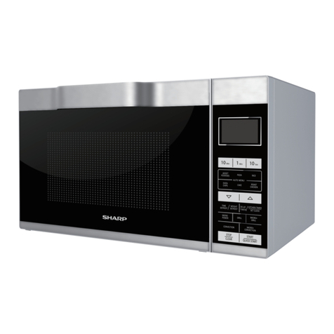
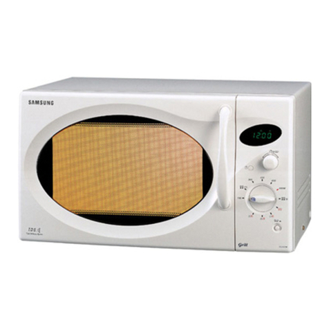
Sharp R-6G10 User manual

R-6G1U(W)
R-6G10(B)
SHARP:
SERVICE
MANUAL
S5807R6G10EHW
GRILL
AND
MICROWAVE
OVEN
MODELS
R-6G10(W)
|
:
In
interests
of
user-safety
the
oven
should
be
restored
to
its
original
|
~)
condition
and
only
parts
identical
to
those
specified
should
be
used.
es
(RD16101U)
:
3
i
|
FOREWORD...
cecesceceereesseerseetteeetcn
CAUTION,
MICROWAVE
RADIATION
......eeee
oe
cescicucnsipetbasbtanddsesotnsaodobieongno
BPE
is
dceat
custusadeeas
SE
DUCT
DESCHIRTION:
scuincrsieccenieerciesasrnnm
eres
Te
a
tana
2
OPERATION
INSTRUCTIONS.
..-cscssssssssssstesseensecrensanssnnsernenrenecerscnnnnnassnssessr
e275
ddan
he
lvuagatetaeeeieasaes
On
3
BEA
TION
a
scr
ne
yee
aan
en
eee
ee
ee
een:
4
SERVICING
cssssssccsssssssressessosersanneceereersensupvneseessnte
gst
ET
so
Seaicuagacuaisancesu
Manwuwuncs
tasenaeeetes
12
‘
COMPONENT
REPLACEMENT
AND
ADISUSTMENT
PROCEDURE
.-...---ssssssceeesterrssereereceersnterennn
ree
21
inch
MICROWAVE
MEASUREMENT
PROCEDURE
Nrd
cc
Aanies
ieaatiesa
uetbenrauametae
aateer
tie
mrtmnaeets
28
POSITION
OF
THE
WIRE
TIES
Ege
eagles
sets
te
ce
cto
ce
ev
UaunG
ie
Serene
RIDE
IS
SE
29
SE
GRIAL
DIAGRAM
suasasiliccssasictesaewteccrennreneenreee
ee
8
cease
30
Se
IST
icsestct
ces
esetonte
eens
ere:
VT
aed
ace
31
PACKING
AND
at
aa
sislavudennsnebesennsbonsseavanesauantoreasseensniveathe®
38
i
SHARP
CORPORATION

R-6G10(W)
|
R-6G10(B)
|
!
a!
f
\
.
aoe
i
i
ao
%
4
i
<
s
~~.
i
is

SS
ae
SERVICE
MANUAL
SHARP
GRILL
AND
MICROWAVE
OVEN
R-6G10(W)/
R-6G10(B)
FOREWORD
This
Manual
has
been
prepared
to
provide
Sharp
Corp.
Service
Personne}
with
complete
Operation
and
Service
Information
for
the
SHARP
GRILL
AND
MICROWAVE
ovens,
R-6G10(W)/
R-6G10(8).
It
is
recommended
that
service
personnel.
carefully
study
the
entire
text
of
this
manual
so
they
will
be
qualified
to
render
—
satisfactory
customer
service.
Check
interlock
switches
and
door
seal
carefully.
Special
at-
_
tention
should
be
given
to
avoid
electrical
shock
and
microwave
radiation
hazard.
CAUTION,
MICROWAVE
RADIATION
Personnel
should
not
be
exposed
to
the
microwave
energy
|
which
may
radiate
from
the
magnetron
or
other
microwave
generating
devices
if
it
is
improperly
used
input
and
output
microwave
connections,
waveguides,
flanges
and
gaskets
must
be
secured.
Never
operate
the
device
without
-
4a
microwave
energy
absorbing
load
attached.
Never
look
into
an
open
waveguide
or
antenna
while
the
device
is
energized.
Note(Parts
List)
:
The
parts
marked
"
*”
are
used
in
voltage
more
than
250V.
SHARPCORPORATION
—
OSAKA,
JAPAN
(RD37201U)
~
(RD36102U)
-
or-connected..
All.
(RD36202U)
R-GUTUCW)
R-6G610(8)

R-6G10(W)
-
A-6G10(B):°
;
PRODUCT
DESCRIPTION
SPECIFICATION
|
CTEMSCS~*S
DESCRIPTION
220
Volts
.
Power
Requirements
50
Hertz
Single
phase,
3
wire
earthed
Microwave
cooking
1.25
kw
Dual
cooking
2.55
kW
Grill
cooking
1.35
kw
600
watts
nominal
of
RF
microwave
energy
(2
liter
water
load)
Operating
frequency
of
2450M
Hz
1.3
kW
Width
520
mm
a
‘Height
341
mm
including
foot
Depth
416
mm
Width
340
mm
Height
203
mm
Depth
350
mm
330mm
60
min.
Dual!
Speed
Timer
Microwave
Cooking
Control
Repetition
Rate;
Power
Consumption
Power
Output
Grill
Heating
element
Power
Output
Case
Dimensions
Cooking
Cavity
Dimensions
Turntable
diameter
Control
Complement
FULL
POWER
.......
Full
power
throughout
the
cooking
time
HORST:
sti
tentaind
a
gach
approx.
70%
of
Full
Power
SIMMER
esscaccicsnscacvissiiencc
approx.
50%
of
Full
Power
DEFROST
|
dive
miatccsnntaidcueken
approx.
30%
of
Full
Power
VOM
=
oes
hight,
nge
8
approx.
10%
of
Full
Power
Cooking
Start
Button,
Cooking
Mode
Selector
Microwave
cooking,
Grill
cooking,
Dual
cooking
Approx.
23
kg
(RD44101U)
GENERAL
INFORMATION
WARNING
THIS
APPLIANCE
MUST
BE
EARTHED
IMPORTANT
THE
WIRES
IN
THIS
MAINS
LEAD
ARE
COLOURED
IN
ACCORDANCE
WITH
THE
FOLLOWING
CODE:
GREEN-AND-YELLOW
:
EARTH
BLUE
>:
NEUTRAL
BROWN
:
LIVE
{RD61107U)
NOTE:
Numbers
and
letters
shown
after
sentences
such
as
"RD44101U”
are
for
factory
use
only.
2

ene
OPERATING
INSTRUCTIONS
1.
Waveguide
cover
2.
Oven
lamp
3,
Access
cover
for
oven
lamp
replacement
4.
Ventilation
openings
5.
Grill
heater
unit
6.
Oven
door
with
see-through
window
7.
Door
latches
8.
Hinges
9.
Roller
stay
10.
Removable
turntable
11.
Low
rack
(50'mm).
12.
High
rack
(135
mm)
_
13.
Cooking
mode
selector
MICROWAVE
[HE]
GRILL
DUAL
COOK
14.
Dual
speed
timer
{0-60
min)
|
45.
Microwave
cooking
control
{10—
100%)
46.
Cooking
start
button(
D)
17.
Door
open
button
{
\
}
K-6UTU(W}
R-6G10(B)

R-6GT0(W)
R-6G610(B)
OPERATION
DESCRIPTION
OF
OPERATING
SEQUENCE
The
following
is
a
description
of
component
functions
during oven
operation.
(RD71101u)
OFF
CONDITION
:
Closing
the
door
activates
heater
Switch
and
2nd
latch
switch
(In
this
condition,
the
monitor
switch
contacts
are
opened.)
With
the
timer
dial
at
”
@”
Position
and
the
door
closed,
no
components
in
the
oven
will
Operate.
(Figure
0-1).
Note:
When
the
door
is
opened
or
the
timer
is
set,
the
“oven
lamp
comes
on.
MICROWAVE
COOKING
CONDITION
Set
the
cooking
mode
selector
to
"i
fi)
‘MICRO-
WAVE”.
The
switch
condition
are
as
follows.
Switch
Contact
Condition
Micro
Select
Switch
COM-NC
Close
Grill
Select
Switch
COM-NC
Open
2nd
latch
Switch
COM-NO
Close
COM-NC
Open
COM-NO
Close
COM-NC
Open
Heater
Switch
.
Close
Monitor
Switch
FULL
POWER
COOKING
i
When
the
door
is
closed,
the
contacts
COM-NO
of
the
2nd
latch
switch
and
monitor
Switch
are
activated.
The
microwave
cooking
contro!
is
set
to
"(
cH
)FULL
POWER’
position
an
cooking
time
is
selected
by
turn-
ing
the
timer.
.
When
turning
the
timer,
the
oven
lamp
lights.
When
the
“COOKING
START’
button
is
pushed,
the
following
operations
occur.:
(Figure
0-2)
1-1.
The
contacts
of
1st
latch
&
cook
switch
are
closed.
1-2.
Then
Following
components
are
energized.
O
:
energized
:
de-energized
Oven
lamp
Oo
Power
transformer
O
Heater
relay
O
Surge
relay
O
Timer
motor
oO
Fan
motor
oO
Turntable
motor
Oo
Magnetron
Oo
Grill
heating
-
element
Or
1-3.
220
voits
A.C.
is
supplied
to
the
primary
winding
of
the
power
transformer
and
is
converted
to
about
3.30
volts
A.C.
output
on
the
filament
winding,
and
approximately
1950
volts
A.C.
on
the
high
voltage
winding.
1-4.
The
filament
winding
voltage
heats
the
magnetron
filament
and
the
H.V.
winding
volt-
age
is
sent
to
a
voltage
doubler
Circuit.
1-5.
The
microwave
energy
produced
by
the
magnetron
is
channeled
through
the
waveguide
into
the
cavity
feed
~box,
and
then
into
the
cavity
where
the
food
is
placed
to
be
cooked.
1-6.
Upon
compietion
of
the
selected
cooking
time,
the
timer
bel!
rings,
and
contacts
of
the
timer
are
open,
then
the
activated
components
as
item
1-2
are
de-energized.
The
oven
reverts
to
the
OFF
condition.
1-7.
The
monitor
switch
is
electrically
monitoring
the
operation
of
the
1st
latch
&
cook
switch
and
is
mechanically
associated
with
the
door
so
that
‘it
will
function
in
the
following
sequence.
(1)
When
the
door
opens
from
closed
position
during
cooking,
the
1st
latch
&
cook
switch
first
operates
to
open
its
contacts,
and
then
the
monitor
switch
contacts(COM-NC)
close,
-
and
2nd
latch
switch
contacts(COM-NO)
open,
and
then
heater
switch
contacts
open.
(2)
When
the
door
is
closed
from
open
position,
the
contacts(COM-NC)
of
the
the
monitor
switch
open
and
2nd
latch
switch
contacts(COM-NO)
first
close
and
then
the
contacts
of
heater
switch
close.
If
the
1st
latch
&
cook
switch
fails
with
its
contacts
closed
when
the
door
is
opened,
closing
of
the
monitor
switch
contacts(COM-NC)
will
form
a
short
Circuit
through
the
fuse,
monitor
resistor
and
1st
latch
&
cook
Switch,
causing
the
fuse
to
blow.
ROAST,
SIMMER,
DEFROST,
WARM
COOKING
When
Variable.
Cooking
Power
is
programed,
the
220
volts
A.C.
is
supplied
to
the
power
transformer
intermittently
through
the
vari-switch
within
a
30
sec-
ond
time
base.
Microwave
Power
operation
is
as
fo}-
lows:
VARI-MODE
ON
TIME
OFF
TIME
FULL
PowEQ
oe
FULL
POWER
30
sec.
0
sec.
(100%
power)
ROAST
24
sec,
6
sec.
(approx.
70%
power)
SIMMER
18
sec.
12
sec.
(approx.
50%
power)
DEFROST
12
sec.
18
sec.
(approx.
30%
power)
WARM
§
sec.
24
sec.
_
(approx.
10%
power)
Note:
The
ON/OFF
time
ratio
does
not
correspond
with
the
percentage
of
microwave
power,
be-
Cause
approx.
2
seconds
are
needed
for
heating
of
the
magnetron
filament.
(RO71403LU)
~i

DUAL
COOKING
CONDITION
In
this
condition,
the
food
is
cooked
by
both
micro-
wave
energy
and
grill
heating
energy
simultaneously.
Set
the
cooking
mode
selector
to
:
DUAL
COOK”.
The
switch
condition
are
as
follows.
Contact
Condition
“COM-NC_
Close
COM-NC
Close
COM-NO
Close
-
COM-NC
Open
COM-NO
Close
COM-NC
Open
Close
—
Heater
Switch
Switch
Micro
Select
Switch
~
Grill
Select
Switch
2nd
latch
Switch
Monitor
Switch
Set
the
desired
cooking
time
by
turning
timer.
You
can
select
the
microwave
power
levels.
When
the
"COOKING
START”
button
is
pushed,
the
following
operations
occur.
(Figure
O-4)
1,
2.
The
contacts
of
1st
latch
&
cook
switch
are
closed.
Then
Following
components
are
energized.
OQ:energized
—:
de-energized
___O:energized_—
(ce
Oven
lamp
.@)
Power
transformer
O
Heater
relay
om
Surge
relay
e)
Timer
motor
ae)
Fan
motor
O
Turntable
motor
oO
Magnetron
oO
_
Grill
heating
Oo
.
element
eee
Now
the
food
is
cooked
by
microwave
and
grill
-
heating
element
energy
simultaneously.
Upon
completion
of
the
selected
cooking
time,
the
timer
bell
rings,
and
contacts
of
the
timer
are
opened,
then
the
activated
components
as
item
2
are
de-energized.
‘The
oven
reverts
to
the
OFF
condition.
But
the
fun
motor
rotates
when
the
temperature
of
‘cooling
thermal
cut-out
is
higher
than
400
°C.
When
it
becomes
lower
than
80
°C,
the
fan
motor
will
stop
rotating
automatically.
R-6G10(W)
R-6G10(B)
GRILL
COOKING
CONDITION
tn
this
condition,
the
food
is
cooked
by
grill
heating
element
energy.
Set
the
cooking
mode
selector
to
”
The
switch
condition
are
as
follows.
(W}
GRILL’.
ee
Switch
Contact
Condition
Micro
Select
Switch
COM-NC
Open
Grill
Select
Switch
COM-NC
Close
2nd
latch
Switch
COM-NOQ
Close
COM-NC
Open
COM-NO
Close
COM-NC
Open
Heater
Switch
Close
.
___
Heater Switch
Monitor
Switch
Set
the
desired
cooking
time
by
turning
timer.
You
can
not
set
the
disired
temperature.
When
the
“COOKING
START”
button
is
pushed,
the
following
operations
OCCUT..
(Figure
0-3)
4.
The
contacts
of
1st
latch
&
cook
switch
are
closed.
2.
Then
Following
components
are
energized.
O-:energized
—:
de-
energized
Oven
lamp
©
‘
Power
transformer
—
Heater
relay
O
Surge
relay
-
Timer
motor
@)
Fan
motor
O
Turntable
mator
ao
Magnetron
-
Gril!
heating
O
element
|
3.
Now
the
food
is
cooked
4.
Upon
completion
of
the
selected
cooking
time,
the
timer
bell
rings,
and
contacts
of
the
timer
are
opened,
then
the
activated
components
as
item
2
are
de-energized.
.
The
oven
reverts
to
the
OFF
condition.
5.
But
the
fun
motor
rotates
when
the
temperature
of
cooling
thermal
cut-out
is
higher
than
100
*C.
When
it
becomes
lower
than
80
°C,
the
fan
motor
will
stop
rotating.
automatically.

Ad0tZa¥
waistLogzu
ADVATOA
HDI
{.43Ig129aH
YIWHOSSNVUL
HIME
"2-0
aunbi4
moz/aL
a
alt
es
HOLSISAY,
aDUNS
UOILIPUOD
44
—
IeWaYIS
UGAQ
“L-—
aNBry
AvoLZa¥
Walsu9au
bated
psi
fadily
sa"
3OVLIOA
HDIN
ee
ee
vOLIDWE¥O
w3ld|LI4au
HAINHOASNYUL
HIMCd
4
MOTHR
=
So
oes
L
dA¥1
N3AG
(70)
H3LIMS
9
I
3,S2t
eine
ino-ina
A
t
ett
aay
eee
ee
=
TV
HIHL
{
watvaH
|
¥3LV3SH
t
]
I
1 j
t
:
*
t
s
s
Io
6
.
1
t
2N3N372
0
-HOLIMS
J
4
!
on
Lnawaya
2.ah
ua1¥3H
ONIvay
UiLVaH
G3HSMid
»
Q
NOLEN
|
ino-ina
pals
fa
peda
LUYVIS
ONINOOD..
'S
awa
ar)
uaMOd
inde
NOULIND
YA
oa.
“fioisins
HoLwas
-
I
—-
Sinourms
HOLIMS
WOLINOW
ONIMOOS
SAYMOUDIN
“PF
a9a7as
Ties
ayn
on
»
HD
AAVMONIIN.,
Loa1a$
THN
«
@)
JAVMOUSING
I"
oN
3GOW
SNINOOD
‘e
S00
BNINOOS
‘
1
eS
NOILISOd
«.@
«NG,
HIN
°°
i
(
mozis'e
Hodsis3u
HOLINONW
G3SO1D
wood
*L
ane
™
;
sitgicbiaapetaos
Pa
cea
0
“aab01o
uoud
<
1
HOLIMS\
Hotta
N3ZA0
20
Me
0)
oO
(n00%
waint
}
WOLIMS
N3A0
40
a
WIOTHALNI}
"
NOOS
NOLLIGNOS
!3.L0N
ead
[
338
TRo-ins
Awd)
9
5002
d
NOILIONO
#3.10N
z
Alvwiud/
¢
49107
4
sind
TVNHSHL
ONITOOD
SL
WYAWHY3HL
ONITOOD
(m3)
SILVASHODS
a
0
(nd)
A
ALYAWIHOS
YOLOM
NVA
YOLOW
N¥4
“NIA
,WIMIS"L
30
VaHV
TYNOIMLOaZS:
Si
FMULS
MOTIZA
ONY
NaTHS:
AD
anva:nte
NMOWB
+
NYU
“NIW
wwe’
L
40
V3u¥
IVNOILI9S*
SL
3dtULS
MOTTIA
ONY
N33uN9*
AD
ane?
aig
ADSZIV/M2r00'O
- .
YOLISYd¥
SS¥dAB
ANI
:
AOSZIYViTZPDO'D
i"
4
AGSZIV/"ZP00'O
HOLMIVdvo
SS¥dAg
SNI7-
HOLIDVdv3
SS¥dAg
NIT:
R-6G10(W)-
-
6G10(B)'
A0SzZOVMzzO
HOLISVd¥9
SS0H9
SNITF
ZHOS-A0ZS
<
NMOKG
‘
NHB
NOFLDaNNOS
aHOI
DY
ms'aynokg
“YE
|
b
AoSZoviZz'O
!
HOLIOVd¥3
SSOuD
INI7
WOO
NOMSINeds
TRON
4D]
re
eee
oe
SS
SS
ee
a
aos
yeu
sua-n
Cote)
Z
@
suNue
SL/N
CH)
ZHOS-A0ZS
NOILIINNOS
GEO?
OF

R-6G1U(W)
R-6G10(B)
uopuoy
Gulyoo9
Jeng
—
IFeWAYS
uaAD
‘+O
anbly
—
ppoizay
w3lg119394
Yplercoub
laa
"Z0't
201104
HDIH
BOLIS
Wao
H
walal193y
HAIAWOISNV
EL
H
aM0d
L
ee
ep
inawata
HOLS
oNiLvaH
walvaH
us
“FOLIMS
HOLIMS
°
SSOLINCN
193735
THHD
moze
HO1SISAH
YOLINOI
(vooneazst
HOLIMS
AT¥ilud,
q
2,001
LNG-LNS
IWHH4HL
ONITOOS
O a
BOLOW
NWS
——
oe
ee
——————
AVSZIW/7*LFNC'O
AQSZIV/"2700'O
YOLID¥d¥O
SSVdAR
antl
ADSZIWMEZZ'O
BOLID¥d¥3
SSOH9
3NIT
HOLID¥dw)
SSV4AB
ANID
|
aaHsnd.
©
NOLLNE
LHVIS
SNINOOS.
'S
«4p
HAMOd
T1Nds
TOBLNOO
PNINOOD
SAYMOHOIN
'¥
“
ms
wd.
3ZQOW
ONINOOS
‘E
oNGe
HAWLL
'Z
G3aso13
HOO
‘ht
NAO
40
NOILIGQNOO
‘3.L0N
DILVASHOS
‘NIWA
wuws"t
10
wad
TWNOLLDaS:
sb/
aa1HLS
MOTTAA
ONW
N32ZUO*
AD
anda:
na
NMOS
?
NHE
NOILOANNOD
OHO3
O¥
uorpuog
BuLjoo7
HJ45
—
aeWUaYDS
UEAQ
*€-O
ani
canoe.
<
.
*
SAMOREEN
walatioay
mo.
“Azo'b,
-ZOVLTOA
HOH
=eraue
O
BOLINVeYD
=
HAWHOASNV
EL
HaMOd
MOZ/OL
‘
WOLSISAH
.
ice
hel
ace
aDuns
HOLIMS
Inawata
HOLIMS
DNILWaH
4Yai¥3H
WHO
asxHsnd..
>
NOLING
LUVLS
DNIXOOS
"F
”
fst1))
VS
AQOW
ONINGOS
'E
oNO.
HAWILL
“%
a3S019
H00"0
*t
.
HOL1MS
tHLLIMS
HOLINON
193735
Tuo
moz/e't
HOLSISAY
HOLINOW
creniT
Weee
N3AO
30
'
WOOTHALNI
:
300k
LOLA
¢
AlvMilid/
9
NOLLIGNOS
‘ALON
—_————_
70
TwinwaHL
ont
2
DILYWAHIS
"NI
wus’,
40
WaH¥
TVNOIL93S?
SL
aoszaviMzroo'O
|
AOSZOW/LPOO'O
:
HOLIDVd¥D
SSVSAB
BOLID¥a¥2
SS¥dAS
3NIT
AdlLS
MOTIZA
ONY
N33HD*
AD
anta:
m8
NMOH@
?
NYG
NOLLOAZNNOS
GuOJ
JY
AggzawimzZzo'
HOLIDVAYD
SSOWD
INIT
Slinda
sing
ZHOS™AOZE
—_———

R-6G10(W)
R-6610(B)}
DESCRIPTION
AND
FUNCTION
OF
COMPONENTS
1ST
LATCH
&
COOK
SwitcH
This
switch
functions
both
as
a
latch
switch
and
the
cook
switch.
Operation
is
as
follows.
1.
When
the
door
is
closed,
the
lower
latch
head
snaps
down
above
the
switch
lever
which
causes
not
to
close
the
switch.
2.
When
the
start
button
is
pressed,
it
pushes
the
Switch
lever.
The
switch
lever
now
depresses
the
plunger
of
the
switch
closing
its
COM-NO
contacts
(ON
condition).
3.
When
the
open
button
is
Pressed,
it
pushes
the
open
lever.
The-open
lever
raises
the
switch
lever
raising
the
lower
latch
head.
As
that
time,
the
switch
lever
is
released
from
the
plunger
of
the
1st
latch
&
cook
switch.
The
switch
lever
is
returned
to
its
original
position.
Now,
the
COM-NO
contacts
of
the
switch
opened
(OFF
condition).
2ND
LATCH
SWITCH
:
The
switch
is
activated
by
the
upper
latch
head
on
the
door.
When
the
door
is
Opened,
the
switch
interrupts
the
Circuit
to
all
components,
except
oven
lamp
and
fan
motor.
Then
the
cook
cycle
is
stopped.
A
cook
cycle
cannot
take
place
until
the
door
is
firmly
closed
and
the
start
button
is
depressed
with
the
timer
set.
>
HEATER
SWITCH
The
heater
switch
is
located
at
the
latch
hook.
.
The
contacts
of
the
heater
switch
are
mechanically
opened
by
opening
the
door,
and
closed
by
closing
the
door.
DOOR
OPEN
MECHANISM
The
door
can
be
opened
by
pushing
the
open
button
on
the
contro!
panel.
When
the
open
button
is
pushed,
the
open
lever
pushes
switch
lever.
The
switch
lever
pushes
lower
latch
head
on
the
door
upward.
The
upper
latch
head
is
linked
with
the
lower
latch
lead,
So
now,
the
door
can
be
opened.
MONITOR
SWITCH
| |
The
monitor
switch
is
activated
(the
COM-NC
contacts
opened)
by
the
lower
latch
head
on
the
door
while
the
door
is
closed.
The
switch
is
intended
to
render
the
oven
inoperative
by
means
of
blowing
the
fuse(F6.3A)
when
the
contacts
of
the
ist
latch
&
cook
switch
fail
to
open
when
the
door
is
opened.
Function
1.
When
the
door
is
Opened,
the
monitor
Switch
COM-NC
contacts
close
{to
the
ON
condition)
due
to
their
being
normally
closed.
At
this
time
the
1st
latch
&
cook
switche
is
in
the
OFF
condition
(contacts
open)
due
to
their
being
normally
open
contact
switches.
2.
As
the
door
goes
to
a
closed
position,
the
monitor
switch
COM-NC
contacts
are
first
opened
and
then
the
1st
latch
&
cook
switch
contacts
close
when
the
cook
button
is
depressed.
(On
Opening
the
door,
each
of
these
Switches
operate
inversely.
)
3.
If
the
door
is
opened,
and
the
‘st
latch
&
cook
Switch
contacts
fail
to
open,
the
fuse
blows
simul-
taneously
with
closing
of
the
monitor
switch
COM-NC
contacts.
:
CAUTION:
BEFORE
REPLACING
A
BLOWN
FUSE
TEST
THE
1ST
LATCH
&
COOK
SWITCH
AND
MONITOR
SWITCH
FOR
PROPER
OPERATION.
(REFER
TO
CHAPTER
“TEST
PROCE-
DURE”).
Door
2nd
latch
Switch
Upper
Heater
Switch
monitor
Switch
Switch
Switch
lever
Open
lever
Open
button
Figure
D-1.
Door
Open
Mechanism

TIMER
ASSEMBLY
Timer
Contacts:
St
Ps
The
timer
contacts
are
mechanically
opened
or
closed
by
turning
the
dial
knob
located
on
the
timer
motor
shaft.
Vari-switch:
;
The
vari-switch
is
operated
by
the
cam
roller,
If
the
variable
cooking
control
is
set
at
ROAST,
SIMMER,
DEFROST,
WARM
COOKING
position,
220
voits
A.C.
is
supplied
to
the
power
transformer
intermittently
within
a
30
seconds
time
base.
The
following
chart
shows
the
vari-switch
operation
in
the
various
modes.
VARI-
MODE
ON
TIME
OFF
TIME
FULL
POWER
30
sec.
O
sec.
(100%
power)
:
ROAST
24
sec.
6
sec.
(approx.
70%
power)
SIMMER
18
sec.
12
sec.
(approx.
50%
power)
DEFROST
12:
sec.
18
sec.
(approx.
30%
power)
‘
.
6
sec.
|
24
sec.
-
WARM
(approx.
10%
power)
ON:
contacts
of
switch
closed.
OFF:
contacts
of
switch
open.
Note:
The
ON/OFF
time
ratio
does
not
correspond
with
the
percentage
of
microwave
power,
be-
cause
approx.
2
seconds
are
needed
for
heating
of
the
magnetron
filament.
.
MODE
SELECT
MECHANISM,
MICRO.
SELECT
SWITCH
AND
GRILL
SELECT
SWITCH
There
are
micro
cooking
mode,
grill
cooking
mode
and
dual
cooking
mode.
:
The
mode
can
be
set
by
sliding
the
mode
select
knob.
The
mode
select
knob
operates
the
mode
select
as-
sembly
through
the
mode
select
lever.
The
micro
select
switch
and
grill
select
switch
are
controlled
by
the
mode
select
assembly.
The
operations
of
the
two
se-
.
lect
switches
are
as
follows.
Table:
Operation
ofthe
micro
select
switch
and
grit!
select
switch
-
Position
of
Cooking
—
Gril!
select
Micro
select
;
switch
COM-NC
-
Mode
select
mode
switch
COM-NC
knob
-
eas
contacts
°
contacts
The
left
Microwave
y
ee
:
cial
cooking
Close
Open
The
center
Dual
-
fi
ae
gegen
-
*
eooking
Close
. .
Close
|
The
right
Gil
me:
cooking
Open
'
‘Close
R-6G10{W)
R-6G10(8)
MICROWAVE
COOKING
When
sliding
the
mode
select
knob
to
the
left
,
the
mode
select
assmbly
releases
the
plunger
of
the
>
micro
select
switch,
and
it
pushes
the
plunger
of
the
grill
select
switch
at
the
same
time.
Then
the
COM-NC
contacts
of
the
micro
switch
are
closed,
and
the
COM-NC
contacts
of
the
grill
select
switch
are
opened.
.
GRILL
COOKING
~~.
be
When
sliding
the
mode
select
knob
to
the
right
-
wi
the
mode
select
assembly
releases
the
plunger
of
the
grill
select
switch,
and
it
pushes
the
plunger
of
the
micro
select
switch
at
the
same
time.
Then.
the
COM-NC
contacts
of
the
grill
select
switch
are
closed,
and
the
COM-NC
contacts
of
the
micro
select
switch
are
opened.
.
DUAL
COOKING
_When
sliding
the
mode
select
knob
to
the
center
_
the
mode
select
assembly
releases
the
both
plungeres
of
the
micro
select
switch
and
the
grill
se--
lect
switch.
Then
the
COM-NC
contacts
of
the
two
select
switches
are
closed.
.
grill
ee:
-
select
switch
Micro
select
Mode
switch
-
select:
;
:
knob
Control
panel
~_—
frame
f
-
Figure
D-2.
Mode
Select
Mechanism
:
ns
a
aan

=
R-6G10(W)
:
R-6G610(B)
MAGNETRON
THERMAL
CUT-OUT
The
magnetron
thermal
cut-out
is
located
on
the:
to
prevent
damage
to
the:
waveguide
flange
magnetron.
If
the
temperature
of
waveguide
flange
reaches
high
temperature
more
than
approx.
abnormally
when
the
fan
motor
is
locked
or
air
intake
duct
and
ventilation
openings
are
obstructed,
the
magnetron
thermal
cut-out
will
Open.
After
that
when
the
temperature
of
the
waveguide
flange
reduce
lower
than
approx
—20
°C,
the
magnetron
thermal
cut-out
will
close.
Under
normal
operation,
the
magnetron
thermal
cut-out
always
closes.
HEATER
THERMAL
CUT-OUT
The
heater
thermal
cut-out
is
located
on
the
partition
plate
to
prevent
the
temperature
rise
of
the
oven
for
grill
cooking
mode
or
duat
cooking
mode.
lf
the
temperature
of
the
partition
plate
reaches
more
than
approx.
125
°C
abnormally
when
the
fan
motor
is
locked
or
air
intake
duct
and
ventilation
openings
are
obstructed,
the
heater
thermal
cut-out
will
open.
And
the
grill
heating
element
will
be
de-energized.
After
that
when
the
temperature
of
thé
partition
plate
re-
duce
lower
than
approx.
105
°C,
the
heater
thermal
cut-out
will
close.
Under
normal
Operation,
the
heater
thermal
cut-out
always
closes,
COOLING
THERMAL
CUT-OUT
The
cooling
thermal
cut-out
is
located
on
the
exhaust
duct
to
lower
the
temperature
of
the
electronic
or
mechanical
components.
If
the
temperature
of
the
exhaust
duct
reaches
high
temperature
more
then
approx.
100
°C,
the
cooling
thermal
cut-out
will
close
and
the
fan
motor
will
be
energized.
After
that
when
the
temperature
of
the
exhaust
duct
reduce
lower
than
approx.
80
°C,
the
cooling
thermal
cut-out
will
open.
NOISE
FILTER
UNIT
The
noise
filter
unit
is
located
on
the
noise
unit
angle
installed
to
the
rear
cabinet
to
Prevent
the
radio
fre-
quency
interference.
And
it
has
Fuse
134
250V.
FUSE
13A
250V
The
fuse
13A
250V
is
located
on
the
noise
filter
unit.
The
fuse
13A
250V
blows
to
prevent
an
electric
shock
or
a
fire
due
to
excessive
electric
currents
when
the
wire
harness
or
électrical
Parts
are
shorted.
GRILL
HEATING
ELEMENT
The
grill
heating
element
is
located
on
the
reflector.
The
grill
heating
element
sends
out
heat
to
grill
foods.
FUSE
F6.3A
250V
The
fuse
F6.3A
250V
is
located
in
the
fuse
hoider
in-
Stalled
to
the
relay
mounting
plate.
The
fuse
F6.3A
250V
blows
to
prevent
an
electric
shock
or
a
fire
due
to
excessive
electric
currents
when
high
voltage
components,
high
voltage
wires,
wire
harness
or
electrical
parts
are
shorted.
And
also
the
fuse
F6.3A
250V
blows
simultaneously
with
closing
of
the
mon-
itor
switch
COM-NC
contacts
if
the
door
is
apened
and
the
1st
latch
&
cook
switch
contacts
fail
to
open.
115
°C.
10
HEATER
RELAY
Heater
relay
is
located
on
the
relay
mounting
plate
to
open
or
close
the
circuit
to
the
fan
motor
and
grill
heating
element.
SURGE
RELAY
AND
SURGE
RESISTOR
Surge
relay
is
located
on
the
relay
mounting
plate.
wave
cooking
or
dual
cooking
condition,
at
first
the
surge
relay
contacts
open
and
the
surge
current
flows
through
the
Surge
resistor
after
approx.
6
msec.
And
then
the
surge
relay
contacts
close
and
the
current
flows
through
the
Surge
relay
contacts
to
the
power
transformer.
Current.
If
the
surge
resistor
iS
Open,
the
home
breaker,
home
fuse,
fuse
134
250V
or
fuse
F6.3A
250V
may
break
down
when
the
cooking
start
button
is
pushed
microwave
or
dual
cooking
condition.
If
the
surge
relay
contacts
fails
to
close
when
the
cooking
start
button
js
pushed
microwave
or
dua}
cooking
condition,
the
temperature
of
the
surge
re-
sistor
may
rise
high
and
may
damage
the
electric
parts
and
mechanical
parts
around
the
surge
resistor.
MONITOR
RESISTOR
The
monitor
resistor
is
located
on
the
chassis
support.
The
monitor
resistor
Prevents
the
fuse
F6.3A
250V
bursting
when
the
fuse
F6.3A
250V
blows
due
to
the
operation
of
the
monitor
switch.
RECTIFIER
The
rectifier
is
solid
State
device
that
prevents
current
flow
is
both
directions.
And
it
prevents
the
temper-
ature
rise
of
the
power
transformer
by
blowing
the
fuse
F6.3A
when
the
high
voltage
rectifier
is
shorted.
rectifier
_
high
voltage
rectifier
The
rated
peak
reverse
voltage
of
D1
of
the
rectifier
is
6
KV.
The
rated
peak
reverse
voltage
of
D2
of
the
rectifier
is
1.5
KV.
D1
and
D2
of
the
rectifier
or
high
voltage
rectifier
are
shorted
when
the
each
peak
re-
verse
voltage
goes
beyond
the
each
rated
peak
re-
verse
voltage.
(The
process
of
the
blowing
the
fuse
3A.)
The
high
voltage
rectifier
is
shorted
by
any causes
when
microwave
cooking
or
dual
cooking.
The
peak
reverse
voltage
of
D2
of
the
rectifier
goes
beyond
the
rated
peak
reverse
voltage
1.5
KV
in
the
voltage
doubler
circuit.
D2
of
the
rectifier
is
shorted.
The
large
electric
currents
flow
through
the
high
voltage
winding
of
the
power
transformer.
The
targe
electric
currents
beyand
F6.3A
flow
through
the
primary
widing
of
the
power
transfor-
mer.
The
fuse
F6.3A
blows
by
the
large
electric
Currents.
The
oven
stops
its
operation.
The
surge
resistor
puts
down
the
surge

POWER
TRANSFORMER
The
transformer
consists
of
three
windings:
pri-
.
mary,
filament
and
high
voltage.
During
a
cook
cycle,
the
220
volts
A.C.
applied
to
the
primary
winding
of
the
transformer
is
converte
to
3.3
volts
A.C.
on
the
filament
winding
and
ap-
proximately
4950
A.C.
on
the
high
voltage
wind-
ing.
The
3.3
volts
A.C.
heats
the
magnetron
filament.
This
causes
the
tube
cathode
to
readily
emit
the
electrons
necessary
for
tube
conduction
whenever
the
negative
4000
D.C.
voltage
is
applied
to
the
cathode.
R-6651
Ut
Vv)
R-6G10(B)
MAGNETRON
TUBE
The
basic
magnetron
tube
is
a
cylindrical
cathode
within
a
cylindrical
anode
surrounded
by
a
mag-
netic
field.
When
the
cathode
is
heated
by
the
fil-
ament
winding
of
the
power
transformer,
electrons
are
given
off
by
the
cathode.
These
negatively
charged
electrons
are
attracted
to
the
more
positive
anode
of
the
tube
when
the
negative
4000
D.C.
voltage
ts
applied
to
the
cath-
ode.
The
1950
volts
A.C
voltage
is
supplied
to
the
volt-
age
doubler
circuit.
VOLTAG
DOUBLER
CIRCUIT
The
voltage
doubler
circuit
consists
of
a
high
volt-
age
rectifier
and
a
high
voltage
capacitor.
The
4950
volts
A.C.
from
the
high
voltage
winding
of
the
power
transformer
is
applied
to
the
voltage
doubler
circuit,
where
it
is
rectified
and
converted
to
approximately
A000
volts
negative
D.C.
needed
for
magnetron
operation.
Ordinarily,
the
electrons
would
travel
in
a
straight
line
from
the
cathode
to
the
anode
as
shown
in
Figure
D-3.
But
the
addition
of
a
magnetic
field,
provided
by
permanent
magnets
surrounding
the
anode,
causes
the
electrons
to
take
an
orbital
path
between
the
cathode
and
anode,
Figure
D-4.
As
the
electrons
approach
the
anode,
they
travel
past
the
small
resonant
cavities
that
are
part
of
ihe
~
anode.
Interaction
occurs,
causing
the
resonant
cavities
to
oscillate
at
the
very
high
frequency
of
High
voltage
rectifier:
’The
high
voltage
rectifier
is
solid
state
device
that
allows
current
flow
in
one
direction,
but
prevents
current
flow
in
the
opposite
direction.
This
acts
as
a
changing
alternating
current
into
pulsating
2450
megahertz.
This
RF
energy
is
radiated
from
the
magnetron
antenna
into
the
waveguide,
and
|
finally
into
the
cooking
cavity
where
food
has
been
placed
to
be
cooked.
High
voltage
capacitor:
© :
;
The
high
voltage
capacitor
is
able
to
store
energy
on
one
half
of
the
power
cycle
and
then
release
it
along
with
.
the
transformer
output
to
produce
approx.
—
A000
negative
D.C.
volts
to
the
magnetron.
a
WITHOUT
MAGNETIC
FIELD
2450MHZ
COOKING
LOAD
Figure
9-3.
Basic
Magnetron
without
Magnetic
Field
Figure
D-4.
Basic
Magnetron
with
Magnetic
Field
mee,

R-6610(W)
R-6G10(B)
SERVICING
TROUBLESHOOTING
GUIDE
When
troubleshooting
the
oven,
it
is
helpfull
to
follow
IMPORTANT:
{f
the
oven
becomes
inoperative
be-
the
Sequence
of
Operation
in
performing
the
checks.
cause
of
a
blown
fuse
(
F6.3A)
in
1st
Many
of
the
possible
Causes
of
trouble
will
require
that
latch
=&
cook
switch
-
the
monitor
a
specific
test
be
performed.
These
tests
are
given
a
switch
circuit,
check
1st
latch
&
cook
Procedure
letter
which
will
be
found
in
the
“Test
Pro-
switch
and
the
monitor
switch
before
cedure”
section.
replacing
the
fuse
(
F6.3A).
PROBLEM
TEST
PROCEDURE
OR
CORRECTION
POSSIBLE
CAUSE
OFF
CONDITION
Shorted
wire
in
power
cord
or
wire
har-
ness.
Home
fuse
blows
when
power
cord
is
plugged
into
wall
recepta-
cle.
.
2b
ian
5
Fuse(13A
250v)
blows
when
Power
cord
is
plugged
into
wall
receptacle.
Replace
cord
or
check
wiring.
Shorted
‘wire
in
power
cord
or
wire
har-
s.
nes
Replace
power
cord
or
check
e
and
repair
harness,
replace
<2
fuse,
Replace
or
repair.
|
Defective
oven
lamp.
Open
or
foo
R
sé
wire
connection
to
the
eplace
or
repair
Wiring,
above
components.
Oven
lamp
does
not
light
at
door
opened.
DUAL
COOKING
CONDITION
COOKING
CONDITION’.
Defective
heater
switch.
Procedure
J.
(Set
the
cooking
mode
selector
to
DUAL
COOK
and
set
the
timer.)
;
Start
button
is
pushed,
but
the
|
The
oven
Can
not
aperate
at
Gril|
cooking
|
Refer
to
“GRILL
COOKING
oven
does
not
operate
at
Dual
|
condition.
|
CONDITION’.
cooking
condition.
The
oven
can
not
operate
at
Microwave
Refer
to
“MICROWAVE
_
cooking
condition.
Blown
fuse
13A
250V.
Replace
fuse
13A
250V.
Defective
noise
filter
unit.
Open
or
loose
Wiring
to
above
compo-
|
check
and
repair
wiring.
nents,
12

PROBLEM
=
x
’
,
ae
MICROWAVE
COOKING
CONDITION
(Set
the
cooking
mode
selector
to
M
Oven
lamp
does
not
light
with
setting
the
timer.
_
ICROWAVE
and
set
the
timer.)
Defective
the
timer.
|
Defective
oven
lamp
socket.
|
Defective
oven
lamp.
Blown
fuse(F6.3A).
Blown
fuse
13A
250V.
Open
or
loose
wire
conne
above
components.
-
Defective
heater
relay
and
its
contacts.
_|
efective
heater
relay
and
its
contacts.
.
ction
to
the
Fan
motor
doés
not
rotate
when
start
button
is
pushed.
Defective
ist
latch
&
cook
switch.
Mis-adjustment
of
the
1st
latch
switch
&
cook
switch.
latch
Open
or
loose
wire
connection
above
components.
.
Defective
the
timer
or
its
contacts.
Open
or
loose
wire
connection
to
the
above
components.
Timer.
motor
does
not
operate
when
start
button
is
pushed.
-
(Fan
motor
rotates.)
Turntable
“motor
does
not
rota
ion
to
the
when
start
button
is
pushed.
(Fan
motor
rotates:)
te
|
Open
or
loose
wire
connect
turntable
motor.
_
Defective
turntable
motor.
.
Defective
magnetron.
Oven
seems
to
be
operating
but
,
little
or
no
heat
is
produced
in
|
Defective
high
voltage
rectifier
asse
Mic
load.”
a
:
i
Defective
high
voltage
capacitor.
icrowave
cooking
control
is
set
Defective
power
transformer
at
“FULL
POWER”
position.)
a
:
e
Defective
vari-switch
or
timer
motor.
Defective
micro
select
switch.
Defective
heater
switch.
|
|
Defective
surge
relay.
Open
or
loose
wiring
to
above
compo-
|
a
nents.
.
3
fy
gab
Oven
operates
normaly
when
the
Defective
vari-switch
on
the
timer.
-
microwave
cooking
contro!
is
set
at
“FULL
POWER”
position,
but
not
in
any
other
position.
93
mbly.
The
wire
to
the
vari-switch
are
shorted.
Open
or
loose
wiring
to
timer.
Magnetron
ther
Defective
timer.
Fan
motor
stops.
Open
or
loose
wiring
to
above
compo-
nents.
Defective
rectifier.
Oven
steps
as
soon
as
when
the
cooking
start
button
is
pushed.
Oven
goes
into.
cook
.cycle,
but
mal
cut-out
is
opened.
shuts
down’
before
end
of
cycle.
13
POSSIBLE
CAUSE
ie
R-6G10(W)
R-6G10(B)
TEST
PROCEDURE
OR
CORRECTION
PProcedureG.
Procedure
G.
|
Procedure
H.
Replace
oven
lamp
socket.
‘Replace
oven
lamp.
Procedure
N.
Replace
fuse
13A
250V.
Replace
or
repair
wiring.
Replace
fan
motor.
D
Blown
fase
13A
2500.
Blown
fuse(F6.3A).
—
Procedure
N.
eplace
fuse
13A
250V.
,
Procedure
E.
Adjust
the
1st
latch
switch
&
cook
switch
referring
to
“4st
latch
switch,
2nd
latch
switch,
monitor
switch
and
heater
switch
adjustment”.
Replace
or
repair
wiring.
Psocedure
G.
-Replace
or-repair
wiring.
-
©
Check
and
repair
wiring.
|
Replace
turntable
motor.
Procedure
A.
Procedure
D.
|
TprocedureG.
id
Procedure
E.
Procedure
J.
Procedure
L.
Check
and
repair
wiring
7.
a
rocedure
G.
P
Check
and
repair
wiring.
_
Check
and
repair
wiring.
Replace
timer.
Check
and
repair
wiring.
Check
and
repair
wiring.
Procedure
C.

i
A-6G10¢W)
-
'
R-6GT0(8)
-.
PROBLEM
POSSIBLE
CAUSE
|
TEST
PROCEDURE
OR
CORRECTION
GRILL
COOKING
CONDITION
(Set
the
cooking
mode
selector
to
GRILL
and
set
the
timer.)
.
Start
button
is
pushed,
but
grill
|
Defective
grill
heating
element.
heating
element
does
not
Defective
grill
select
switch.
Procedure
E.
operated
(Turntable
rotates.)
Defective
contacts
of
heater
relay.
Procedure
K.
Defective
heater
socket.
Replace
heater
socket.
Defective
heater
switch.
|
Defective
heater
thermal
cut-out.
Open
or
loose
wire
connection
to
abave
|
Check
or
repair
wiring.
:
components.
The
two
terminals
of
grill
heater
unit
does
|
Check
and
fit
the
two
termi-
nals
of
grill
heater
unit
into
not
fit
into
the
heater
socket.
:
the
heater
socket,
referring
“TO
INSTALL
THE
GRILL
Detective
the
timer,
SSCS
HEATER
UNIT’.
Magnetron
thermal
cut-out
is
open.
Defective
oven
lamp
socket.
laplace
even
Terie
Oven
lamp
does
not
light
with
setting
the
timer.
Procedure
N.
Replace
the
fuse
13A
250V.
Replace
fuse
13A
250V.
Open
or
loose
wire
Connection
to
the
|
Replace
or
repair
wiring.
above
components.
Fan
motor
does
not
rotate
when
Replace
fan
motor.
ah
3
start
button
is
pushed.
Defective
heater
relay
and
its
contacts.
Procedure
K.
-
Blown
fuse
13A
250V.
Replace
fuse
13A
250V.
:
Blown
fuse(F6.3A)._
oe
Defective
1st
latch
&
cook
switch.
Mis-adjustment
of
the
1st
latch
latch
|
Adjust
the
1st
latch
switch
switch
&
cook
switch.
&
cook
switch
referring
to
"Ist
latch
switch,
2nd
latch
switch,
monitor
switch
and
heater
switch
adjustment’.
Replace
or
repair
wiring.
cat
|
,
Open
or
loose
wire
connection
to
the
Replace
or
repair
wiring.
|
above
components.
°
Open
or
loose
wirw
connection
to
the
|
Check
and
repair
wiring.
turntable
motor.
. .
Defective
turntable
mator.
|
|
Open
or
loose
wire
connection
to
the
above
components.
Defective
the
timer
or
Timer
motor
does
not
operate
its
contacts.
when
start
button
is
pushed.
(Fan
motor
rotates.)
Turntable
motor
does
not
rotate
when
start
button
is
pushed,
(Fan
motor
rotates.)
eplace
turntable
motor.
|
Procedure
H.
Check
fan
blade,
fan
duct,
fan
motor,
air
intake
duct,
parti-
tion
plate,
exhaust
duct,
and
ventilation
openings.
Start
button
is
pushed,
but
grill
|
Heater
thermal
cut-out
is
opened.
heating
element
stops
it’s
Operate
soon
(after
about
10
minutes).
14

R-6G10(W)
R-6G10(B)
TEST
PROCEDURES
PROCEDURE
LETTER
COMPONENT
TEST
AO
MAGNETRON
ASSEMBLY
TEST
MAGNETRON
ASE
DISCHARGE
THE
HIGH
VOLTAGE
CAPACITOR
BEFORE
TOUCHING
ANY
OVEN
COMPO-
NENTS
OR
WIRING.
To
test
for
an
open
filament,
isolate
the
magnetron
from
the
high
voltage
circuit.
A
continuity
check
across
the
magnetron
filament
leads
should
indicate
less
than
1
ohm.
To
test
for
a
shorted
magnetron,
connect
the
ohmmeter
leads
between
the
magnetron
filament
leads
and
chassis
ground.
This
test
should
indicate
an
infinite
resistance.
If
there
is
little
or
no
resistance,
the
magnetron
is
grounded
and
must
be
replaced.
.
-
Power
output
of
the
magnetron
can
be
measured
by
performing
a
water
temperature
rise
test.
This
test
should
only
be
used
if
above
rests
do
not
indicate
a
faulty
magnetron
and
there
is
no
-
defect
in
the
following
components
or
wiring:
high
voltage
rectifier
assembly,
high
voltage
capacitor,
and
power
transformer.
. .
MICROWAVE
OUTPUT
POWER
.
7
Microwave
output
power
from
the
magnetron
can
be
measured
by
way
of
substitution,
i.e.
it
can
be
measured
by
using
water
load
how
much
it
can
be
absorbed
by
the
water
load.
To
measure
the
microwave
output
power
in
the
microwave
oven,
the
relation
of
calorie
and
watt
is
used.
When
P(W)
heating
works
for
t(second),
approximately
P
x
t/4.2
calorie
is
generated.
On
the
other
hand,
if
the
temperature
of
the
water
with
V(ml)
rises
AT.
(
°C)
during
this
microwave
heating
period,
the
calorie
of
the
water
is
V
x
Al..
<
ue
Pet
i
The
formular
is
as
follows;
a+
4
Pxt/42=Vx
AT
-
P
(W)
=4.2xVx
AT
/t
Our
condition
for
the
water
load
is
as
follows:
—
eR
Water
load...
2000
ml,
Heating
time
140
seconds:
—
ge
"Measuring
method;
—
.
ae
ea
ot
eee
4
Put
the
water
load
of
two
(2)
litres
on
the
center
of
the
oven
shelf.
The
water
toad
should
be
arranged
in
two
(2)
Pyrex
beakers,
the
size
of
which
is
one
(1)
litre,
and
be
placed
at
right
and
left,
side
by
side,
on
the
oven
shelf.
ae
SU
ae
<a
es
.
2.
Measure
the
temperature
of
water
before
heating
and
also
after
heating
during
140
seconds
~-
by
microwave,
and
calculate
the
temperature
rise.
The
temperature
rise
should
be
the
average
of
temperature
differences
measured
in
each
beaker,
0.
te
3.
The
output
power
should
be
calculated
as
follows.
In
case
the
measuring
result
is
not
satis-
-
factory,
execute
the
measurement
several
times
and
judge
the
result
from
the
synthetic
point
_of
view.
Microwave
output
power
should
be
within.
+
15%
of
the
nominal
one.
-
Calculation
of
output
power,
sa,
Ks
a
Microwave
output
power
.P
(W)
=
60x
AT
(
SO
ka
Se
_AT=
(
ATL
+
ATR)
/
2:
average
temperature
rise
.
ATL
=
(TL2-TL1),
ATR=
(TR2
-
TR1)
TL2
:
water
temperature
after
heating
in
left
beaker
‘care
TL1
:
water
temperature
before
heating
in
left
beaker
TR2
:
water
temperature
after
heating
in
right
beaker
TR1
:
water
temperature
before
heating
in
right
beaker
|
Measuring
condition;
..
.
om
_
As
the
microwave
output
is
affected
by
several
conditions,
the
measurement
should
be
made
carefully
with
following
attentions.
--
.
4.
Initial
temperature
of
salt
water
should
be
10
+
1
°C.
Well
and
quickly
stir
the
water
and
the
temperature
measurement
should
be
done
immediately
after
heating.
2.
The
graduation
of
thermometer
should
be
scaled
by
0.1
°C
at
minimum
and
an
accurate
mer-
cury
thermometer
is
recommended.
3.
Water
container
should
be
one
(1)
litre
beaker
made
of
Pyrex
glass
and
its
diameter
approxi-
mately
12
cm.

°
RESGTOEW)..
*
A-6G10(8)
TEST
PROCEDURES
(CONT’D)
PROCEDURE
LETTER
COMPONENT
TEST
4.
Room
temperature
should
be
around
20
°C.
:
5.
Power
supply
voltage
should
be
Specification
valtage.
B
POWER
TRANSFORMER
TEST
.
SSSI
ANSFORMER
TEST
DISCHARGE
THE
HIGH
VOLTAGE
CAPACITOR
BEFORE
TOUCHING
ANY
OVEN
COMPO-
NENTS
OR
WIRING,
On
the
R
x
1
scale,
the
resistance
of
the
primary
coil.
should
be
approx.
1.5
ohm
and
the
resist-
ance
of
the
high
voltage
coil
should
be
approximately
80
ohms;
the
resistance
of
the
filament
coil
should
be
less
than
1
ohm.
(HIGH
VOLTAGES
ARE
PRESENT
TO
HIGH
VOLTAGE
TERMINAL,
SO
DO
NOT
ATTEMPT
TO
MEASURE
THE
FILAMENT
AND
HIGH
VOLTAGE.)
.
Cc
HIGH
VOLTAGE
RECTIFIER
ASSEMBLY
TEST
See
EN
ASSEMBLY
TEST
DISCHARGE
THE
HIGH
VOLTAGE
CAPACITOR
BEFORE
TOUCHING
ANY
OVEN
COMPO.
NENTS
OR
WIRING.
|
HIGH
VOLTAGE
RECTIFIER
TEST
Isolate
the
high
voltage
rectifier
assembly
from
the
circuit.
Using
the
highest
ohm
scale
of
the
meter,
read
the
resistance
across
the
high
voltage
rectifier
terminals
and
observe,
reverse
the
leads
to
the
high
voitage
rectifier
terminals
and
observe
meter
reading.
If
a
short
is
indicated
in
both
directions,
or
if
an
infinite
resistance
is
read
in
both
directions,
the
high
voltage
rectifier
is
prob-
ably
defective
and
should
be
replaced
with
rectifier.
RECTIFIER
TEST
isolate
the
high
voltage
rectifier
assembly
from
the
circuit.
Using
the
highest
ahm
scale
of
the
meter,
read
the
resistance
across
the
rectifier
terminals,
reverse
the
leads
to
the
rectifier
terminals
and
observe
meter
reading.
If
an
infinite
resistance
is
read
in
both
directions,
the
rectifier
is
good.
If
a
short
is
indicated
in
either
direction,
the
rectifier
is
probably
defective
and
should
be
replaced
with
the
high
voltage
rectifier.
When
the
rectifier
is
defective,
check
whether
Magneiron,
high
voltage
rectifier,
high
voltage
wire,
power
transformer
filament
leads
are
shorted.
HIGH
VOLTAGE
CAPACITOR
TEST
REEL
ANE
SAPACITOR
TEST
DISCHARGE
THE
HIGH
VOLTAGE
CAPACITOR
BEFORE
TOUCHING
ANY
OVEN
COMPO-
NENTS
OR
WIRING,
:
continuity
for
a
short
time
and
should
indicate
approximately
10M
Q
once
the
capacitor
is
charged.
If
the
above
is
not
the
case,
check
the
Capacitor
with
an
ohmmeter
to
see
if
it
is
shorted
between
the
terminals.
If
it
is
shorted,
replace
the
Capacitor.
asaneaans
E
SWITCH
TEST
Isolate
the
switch
and
check
the
contacts
by
using
an
ohmmeter
using
the
following
table.
If
improper
operation
is
indicated,
make
the
necessary
switch
adjustment
or
replacement.
Table:
Switch
Connection
Connection
Cammon
Terminal-Normally
Open
Terminal
Common
Terminal-Normally
Close
Terminal
(COM)
(NO)
(COM)
(NC)
Operation
Plunger
released
Bese
ekg
eee
area
cere
16

Ne”
H-GUTUL
WW)
R-6G10(B)
TEST
PROCEDURES
(CONT'D)
PROCEDURE
LETTER
COMPONENT
TEST
F
MONITOR
SWITCH
TEST
latch
hook
MOND
YUA
oe
eee
2nd
jatch
switch
Disconnect
the
oven
from
the
power
supply.
Disconnect
the
wire
jead
from
NC
terminal
of
the
monitor
switch.
Before
performing
this
test,
make
sure
the
1st
latch
&
cook
switch
is
operating
properly
re-
ferring
to
“Switch
Test
Procedure”.
Connect
one
ohmmeter
jead
to
NC
terminal
of
monitor
switch,
and
the
other
lead
to
COM
terminal
of
monitor
switch,
as
shown
figure.
When
the
door
is
opened,
the
meter
should
indicate
a
close
circuit.
When
the
plunger
of
monitor
switch
is
pushed
by
a
screw-driver,
through
the
latch
hook
hole
on
the
front
plate
of
the
oven
cavity
with
the
door
opened,
the
meter
should
‘indicate
an
open
circuit.
In
case
improper
operation
is
indicated,
replace
the
defective
monitor
switch.
After
testing
the
monitor
switch,
re-connect
the
wire
lead
to
NC
terminal
of
the
monitor
switch.
A
|
G
<
~
TIMER
(WITH
VARI-SWITCH)
TEST
TIMER
CONTACTS
TEST
Disconnect
the
wire
leads
from
the
timer.
=
fe.
Mae
; .
With
the
timer
advanced,
a
check
of
contacts
with
an
ohmmeter
should
indicate
(1)
and
(2)
~
eontacts
are
closed.
Whith
the
timer
set
at”
@
“,an
ohmmeter
should
indicate
they
are
opened.
With
220
volts
A.C.
applied
to
the
timer-motor
coil
(5)
and
(6),
check
for
continuity
between
the
vari-switch
contacts
(8)
and
(9).
When
the
microwave
cooking
control
set
at
“HIGH”
po-
sition,
the
meter
should
indicate-a-closed
circuit.
If
set-at-any,
other
position
refer
to
the
following
chart.
oe:
ie
&
“
.
oe
VARILMODE___ONTIME
OFF
TIME
“FULLPOWER—-—=—s—<“‘i‘iéqO
S@”W:«C“«“s‘t«é
sec.
(approx.
100%
power)
eS
rye
ROAST
. ;
24
sec.
|
6
sec.
-
(approx.
70%
power)
‘SIMMER
:
-
18
sec.
12
sec.
-
(approx.
50%
power)
Ne
aneets
DEFROST
12
sec.
18
sec.
(approx.
30%
power)
6
sec.
24
sec.
(approx.
10%
power)
ON:
Meter
indicates
closed.
‘OFF:
Meter
indicates
open.
:
lt
improper
operation
is
indicated,
replace
the
timer.
lf
proper
operation
is
indicated,
check
for
toose
or
broken
wire
connections.
ashe
Peseta
ee
a
tie
After
testing
the
timer,
reconnect
the
wire
leads
to
the
timer
with
referring
to
the
“Pictorial
Dia-
TIMER
MOTOR
TEST
Dee
By
With
the
oven
operating,
check
with
a
voltmeter
at
the
timer
motor
lead.(connected
across
the
timer
coil
5
and
6).
lf
voltage
is
present,
but
the
timer
motor
does
not
turn,
replace
the
timer.
If
no
power,
check
for
loose
or
broken
wiring.
ave
AT

A-6G10(W)
|
R-6G10(8)
©
TEST
PROCEDURES
(CONT'D)
PROCEDURE
LETTER
Sa,
-
H
THERMAL
CUT-OUT
TEST
SSTERMAL
CUT-OUT
TEST
1.
Disconnect
the
wire
leads
from
the
thermal
cut-out,
and
remove
the
thermal
cut-out.
2.
Connect
the
ohmmeter
leads
to
the
thermal
cut-out.
3.
Check
the
indication
of
the
ohmmeter
according
to
the
above
table.
4.
If
improper
operation
is
indicated,
replaced
the
thermal
cut-
out
and
check
the
points
of
the
table
at
the
same
time.
COMPONENT
TEST
After
testing
the
thermal
cut-out,
re-install
the
thermal
cut-out
in
place
and
re-connect
wire
leads
.to
the
thermal
cut-out
correctly
referring
to
“Pictorial
Diagram”.
Heater
thermal
From
125
°C
up.
Cut-out.
Cooling
thermal
From
100
°C
up.
From
80
°C
down.
Open
circuit.
cut-out.
Magnetron
From
—20
°C
down.
From
115
°C
up.
Closed
circuit.
thermal
cut-out.
7
GRILL
HEATING
ELEMENT
TEST
SILL
HEATING
ELEMENT
TEST
Make
sure
the
heating
element
is
fully
cooled
and
test
as
follows;
a.
Remove
the
grill
heater
unit
with
referring
to
"GRILL
HEATING
ELEMENT
REMOVAL”
and
measure
the
resistance
with
an
ohmmeter.
On
the
R
x
1
scale,
the
resistance
between
the
heating
element
terminals
should
be
about
36ohms.
b.
Remove
the
grili
heater
unit
with
referring
to
“GRILL
HEATING
ELEMENT
REMOVAL”
and
measure
the
insulation
resistance
with
500V
-
100M
QO
insulation
resistance
meter.
The
in-
sulation
resistance
between
heating
element
terminal
and
cavity
should
be
more
than
10M
Q.
Table:
Thermal
cut-out
test
Temperature
of
|
“ON”
condition
“OFF”
condition
(closed
circuit).
(open
circuit).
(
°C)
{
°C)
Temperature
of
indication
of
ohmmeter
(When
room
temperature
is
approx.
20
°C.)
Closed
circuit.
Check
points
(When
the
themal
cut-out
is
defective,
or
when
it
operates.
From
105
°C
down.
F
an
blade,
fan
duct,
fan
motor,
air
intake
duct,
ventilation
opening
partition
plate,
exhaust
duct.
J
HEATER
SWITCH
TEST
isolate
the
heater
switch
referring
to
“Heater
switch
removal”.
Connect
the
ohmmeter
leads
between
the‘heater
switch
terminals
(1)
and
(5),
(2)
and
(6),
(3)
and
(7),
(4)
and
(8),
.
And
check
the
each
Operation
according
to
above
table.
If
improper
operation
is
indicated,
replace
the
heater
switch.
.
After
testing
the
heater
switch,
re-install
it
in
place
and
re-connect
wire
leads
to
it
referring
to
“Pictorial
Diagram”,
|
ihe
Ecioee
et
,
Terminal
(4)
-
Another
terminal
(8)
Operation
oc
ae
=
Plunger
released
Plunger
pushed
Closed
circuit
Heater
switch
18
Table:
Heater
switch
operation
Connéction
Terminal
(1)
-
Another
terminal
(5)
.
Terminal
(2)
-
Another
terminal
(6)
Terminal
(3)
-
Another
terminal
(7)
i.)
This manual suits for next models
2
Table of contents
Other Sharp Microwave Oven manuals

Sharp
Sharp Carousel SMC0912BS User manual

Sharp
Sharp R-267LST User manual

Sharp
Sharp R-657 User manual

Sharp
Sharp R-203CW User manual

Sharp
Sharp R-899P User manual

Sharp
Sharp R-35ST User manual

Sharp
Sharp R-22JT User manual

Sharp
Sharp R242WW User manual

Sharp
Sharp R-3A56(W) User manual

Sharp
Sharp R-300BW User manual

Sharp
Sharp R-870B User manual

Sharp
Sharp R-6471L User manual

Sharp
Sharp R-756SLM User manual

Sharp
Sharp R-25A0(W) User manual

Sharp
Sharp Carousel R-380L User manual

Sharp
Sharp R-208 Instruction Manual

Sharp
Sharp R-210B Use and care manual

Sharp
Sharp Carousel R-7A54 User manual

Sharp
Sharp R-320HK User manual

Sharp
Sharp R-330DK User manual