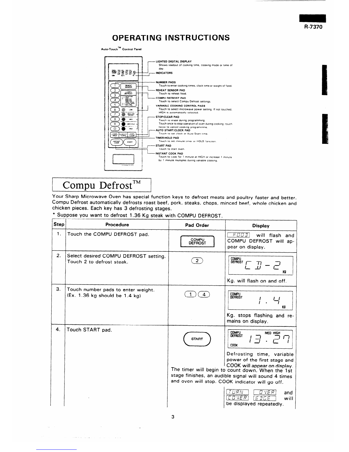
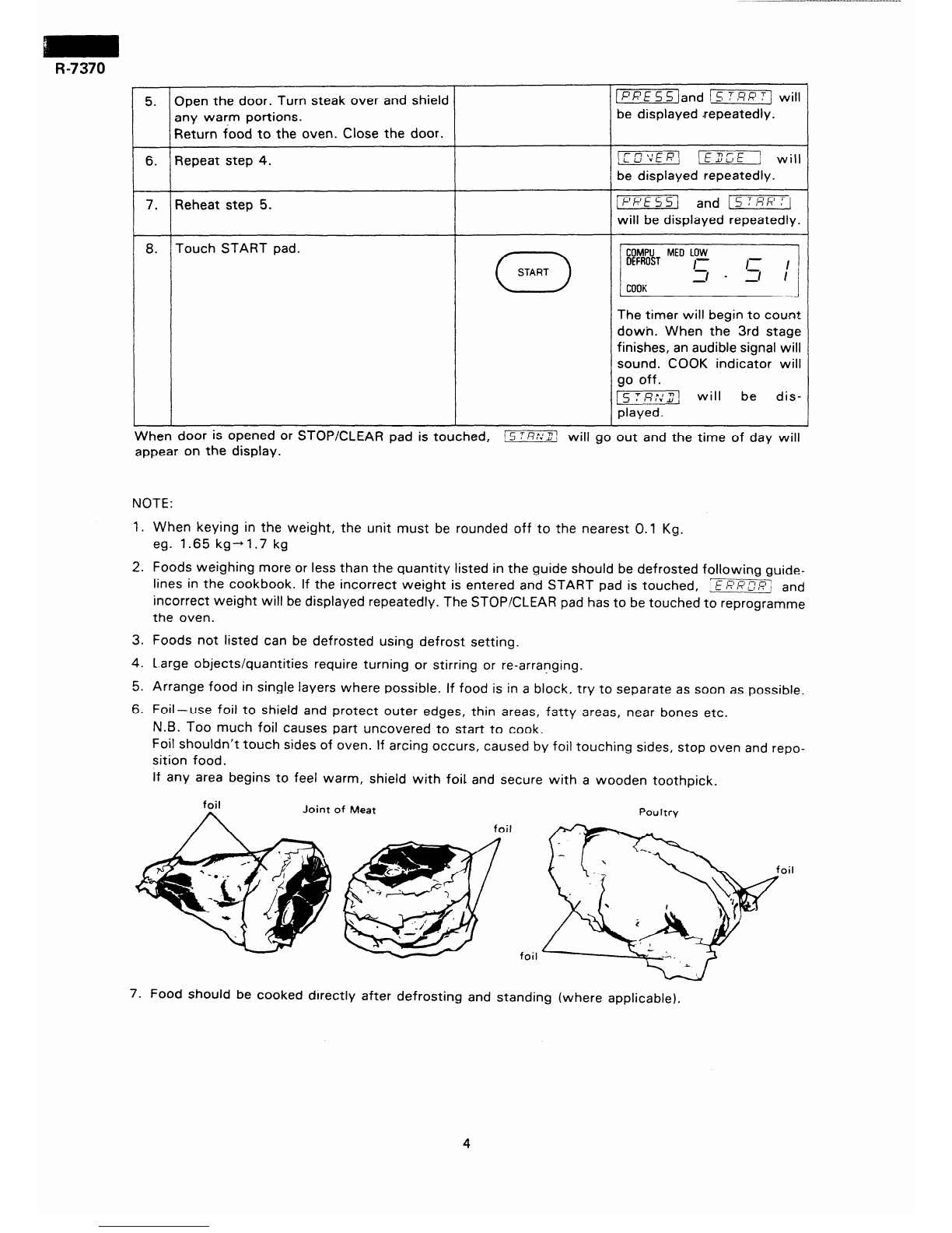
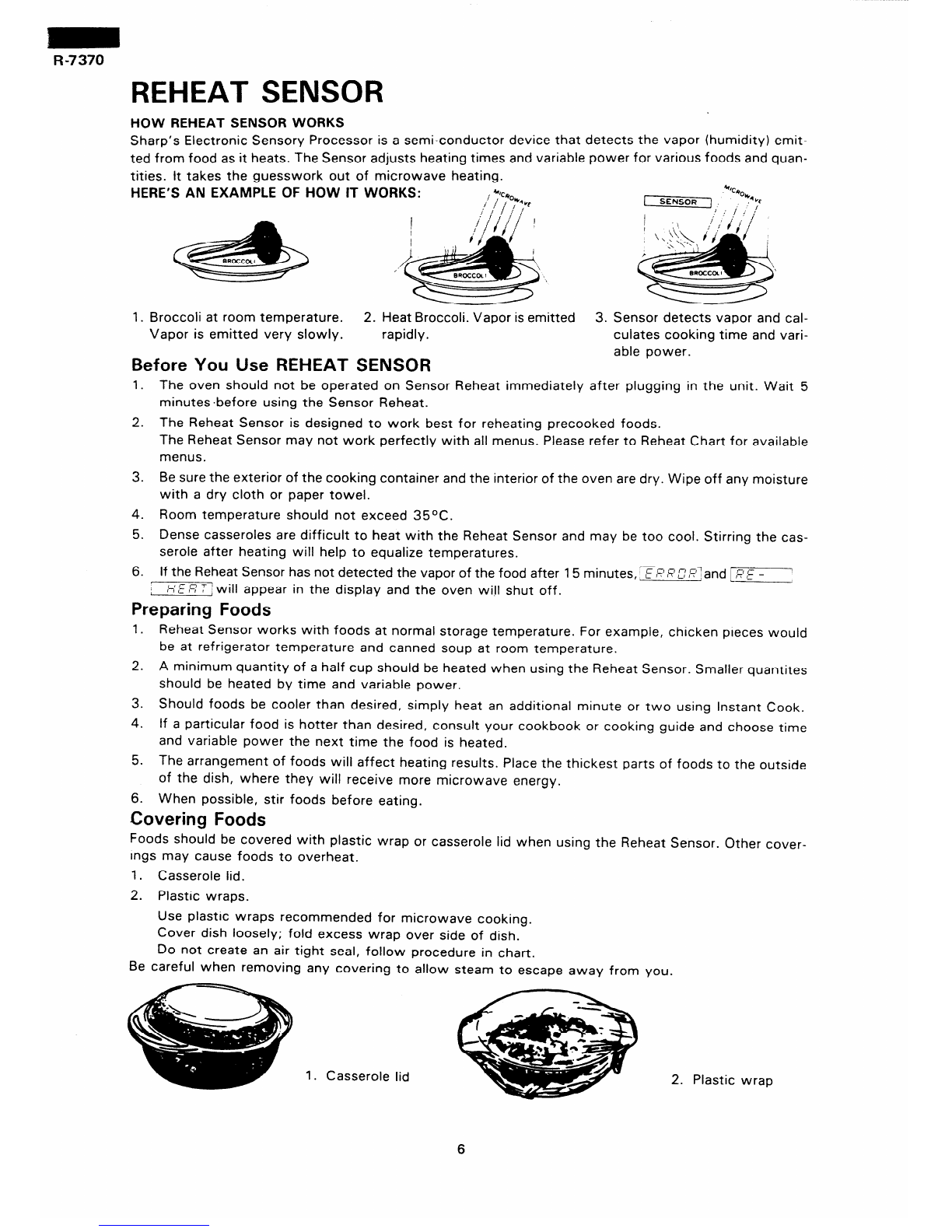
manuals.online logo
Brands
  1. Home
  2. •
  3. Brands
  4. •
  5. Sharp
  6. •
  7. Microwave Oven
  8. •
  9. Sharp R-7370 User manual

Sharp R-7370 User manual

R-7370
SHARF= SERVICE MANUAL
S6606R737OJ//
MICROWAVE OVEN
MODEL R-7370
photo R-7370 In the interests of user-safety the set should be restored to its
original condition and only *parts identical to those specified be
used.
/-- \
This is a supplemental Service Manual for R-7370.
These models are quite similar to Base Model R-7260.
Model R-7370 has Reheat Sensor and Compu Defrost functions in addition, compared to base
model R-7260.
Use this supplemental manual together with the Base Service Manual.
Refer to the Base Service Manual for complete operation, service information, etc.
/ TABLE OF CONTENTS \
Page
FOREWORD ...................................................................... 1
CAUTION, MICROWAVE RADIATION ................................................... 1
THUMB INDEX ................................................................... 1
PRODUCT DESCRIPTION ............................................................ 2
OPERATING INSTRUCTIONS ......................................................... 3
SERVICING ...................................................................... 8
TOUCH CONTROL PANEL ASSEMBLY ................................................. 10
MICROWAVE MEASUREMENT ....................................................... 23
SCHEMATIC DIAGRAM ............................................................ 24
PICTORIAL DIAGRAM ............................................................. 24
CONTROL PANEL CIRCUIT.. ....................................................... 25
PRINTED WIRING BOARD .......................................................... 26
PACKING AND ACCESSORIES.. ..................................................... 27
PARTS LIST .................................................................... 28
SHARP CORPORATION
R-7370
SERVICE MANUAL
SHARP
MICROWAVE OVEN
R-7370
FOREWORD
This Manual .has been prepared to provide Sharp Service
Personnel with complete Operation and Service Information
for the Sharp Microwave Oven.
These models are quite similar to Base Model R-7260.
lt is recommended that service personnel carefully study the
entire text of two Manuals (Base manual and this manual),
SO they will be qualified to render satisfactory customer
service,
CAUTION
MICROWAVE RADIATION
Personnel should not be exposed to the microwave energy
which may radiate from the magnetron or other microwave
generating devices if it is improperly used or connected,
All input and output microwave connections, waveguides,
flanges, and gaskets must be secured.
Never operate the device without a microwave energy absorbing
load attached.
Never look into an open waveguide or antenna while the
device is energized.
SHARP CORPORATION
OSAKA, JAPAN
R-7370 -
PRODUCT DESCRIPTION
EXPLANATION OF MICROWAVE COOKING
The Sharp Microwave Oven uses microwave energy to produce
heat in the food to be cooked. Unlike conventional ovens
microwave energy will cook foods without applying external
heat.
Materials with a high moisture content, like most foods, will
absorb microwave energy. As the microwave energy at a fre-
quency of 2456 Megahertz enters the food, the molecules align
themselves with the energy. Because the microwaves are
changing polarity every half cycle, the food molecules are
Microwaves, which are short electromagnetic waves of RF
(radio frequency) energy, pass through materials such as glass,
paper, china and most plastics. Materials such as metal and
aluminum foil tend to reflect microwaves and may be used
only as recommended in the cooking instructions.
changing direction every half cycle or oscillating back and
forth 4,900,000,000 times per second. This high speed oscil-
lation causes friction between the molecules, thereby convert-
ing the microwave energy to heat.
Power requirements
Power consumption
Microwave output power 650W (2 litre water load)
Case dimensions
Width
Height
Depth
Cooking cavity dimensions
Width
Height
Depth
Turntable diameter
Control complement
Weight
SPECIFICATIONS
240V
50Hz
Single phase, 3 wire earthed
1.3kW
550mm
336mm
403mm
345mm
217mm
344mm
325mm
Start Pad. Stop/Clear Pad.
Clock (1 :00 - 12:59)
Minute Timer (0 - 99 minutes 99 seconds)
Variable Cooking Control
Repetition Rate:
HIGH
Full power throughout the cooking time.
MED HIGH
Approx. 24 sec. ON, 8 sec. OFF, approx. 70% of full power.
MED
Approx. 18 sec. ON, 14 sec. OFF, approx. 50% of full power.
MED LOW/DEFROST
Approx. 12 sec. ON, 20 sec. OFF, approx. 30% of full power.
LOW
Approx. 6 sec. ON, 26 sec. OFF, approx. 10% of full power.
Reheat Sensor, Compu Defrost. - c
Approx. 2 1kg.
2
R-7370
OPERATING INSTRUCTIONS
Auto-Toochm Control Panel
LIGHTED DIGITAL DISPLAY
Shows readout of cookmg tme. cooking mode or tme of
dw
INDICATORS
food
Jched.
-INSTANT COOK PA0
Toucn 10 CJOICfor 1 mmute at HlGcl or tncrease 1 m,nure
by 1 minute mumpies durmg varmie cookmg
i comx>uDefrostTM /
L * 1
Your Sharp Microwave Oven has special function keys to defrost meats and poultry faster and better.
Compu Defrost automatically defrosts roast beef, pork, steaks, chops, minced beef, whole chicken and
chicken pieces. Each key has 3 defrosting stages.
Step
1.
2.
3.
4.-
lose you want to defrost 1.36 Kg steak with COMPU DEFROST.
Procedure Pad Order
Touch the COMPU DEFROST pad.
Select desired’ COMPU DEFROST setting.
Touch 2 to defrost steak.
Touch number pads to enter weight.
IEx. 1.36 kg should be 1.4 kg)
Touch START pad.
[X]
w
0
START
Display
[ will flash and
COMPU DEFROST will ap-
pear on display.
Kg. will flash on and off.
Kg. stops flashing and re-
mains on display.
I
COMPU
OEMIST ME0HIGH
I ’
COOK
Defrosting time, variable
power of the first stage and
COOK will appear on display.
The timer will begin to count down. When the 1st
stage finishes, an audible signal will sound 4 times
3nd oven will stop. COOK indicator will go off.
I=] [=I and
m jm] will
be displayed repeatedly.
3
r- 5. Open the door. Turn steak over and shield !]and ISTRR:] will
any warm portions. be displayed repeatedly.
Return food to the oven. Close the door.
6. Repeat step 4.
7. Reheat step 5.
!TETTl jEU”=li’] will
be displayed repeatedly.
jFRESSI t
and i 5 T,q&‘Tj
will be displayed repeatedly.
8. Touch START pad.
The timer will begin to count
dowh. When the 3rd stage
finishes, an audible signal will
sound. COOK indicator will
go off.
[ S T8 I”:2 j w iII be dis-
played.
When door is opened or STOP/CLEAR pad is touched, !STfi::Z will go out and the time of day will
appear on the display.
NOTE:
1. When keying in the weight, the unit must be rounded off to the nearest 0.1 Kg.
eg. 1.65 kgh1.7 kg
2. Foods weighing more or less than the quantity listed in the guide should be defrosted following guide-
lines in the cookbook. If the incorrect weight is entered and START pad is touched, E RR3R; and
incorrect weight will be displayed repeatedly. The STOP/CLEAR pad has to be touched to reprogramme
the oven.
3. Foods not listed can be defrosted using defrost setting.
4. Large objects/quantities require turning or stirring or re-arranging.
5. Arrange food in single layers where possible. If food is in a block, try to separate as soon as possible.
6. Foil-use foil to shield and protect outer edges, thin areas, fatty areas, near bones etc.
N.B. Too much foil causes part uncovered to start to cook.
Foil shouldn’t touch sides of oven. If arcing occurs, caused by foil touching sides, stop oven and repo-
sition food.
If any area begins to feel warm, shield with foil and secure with a wooden toothpick.
Joint of Meat Poultry
foil
7. Food should be cooked directly after defrosting and standing (where applicable).
4
R-7370
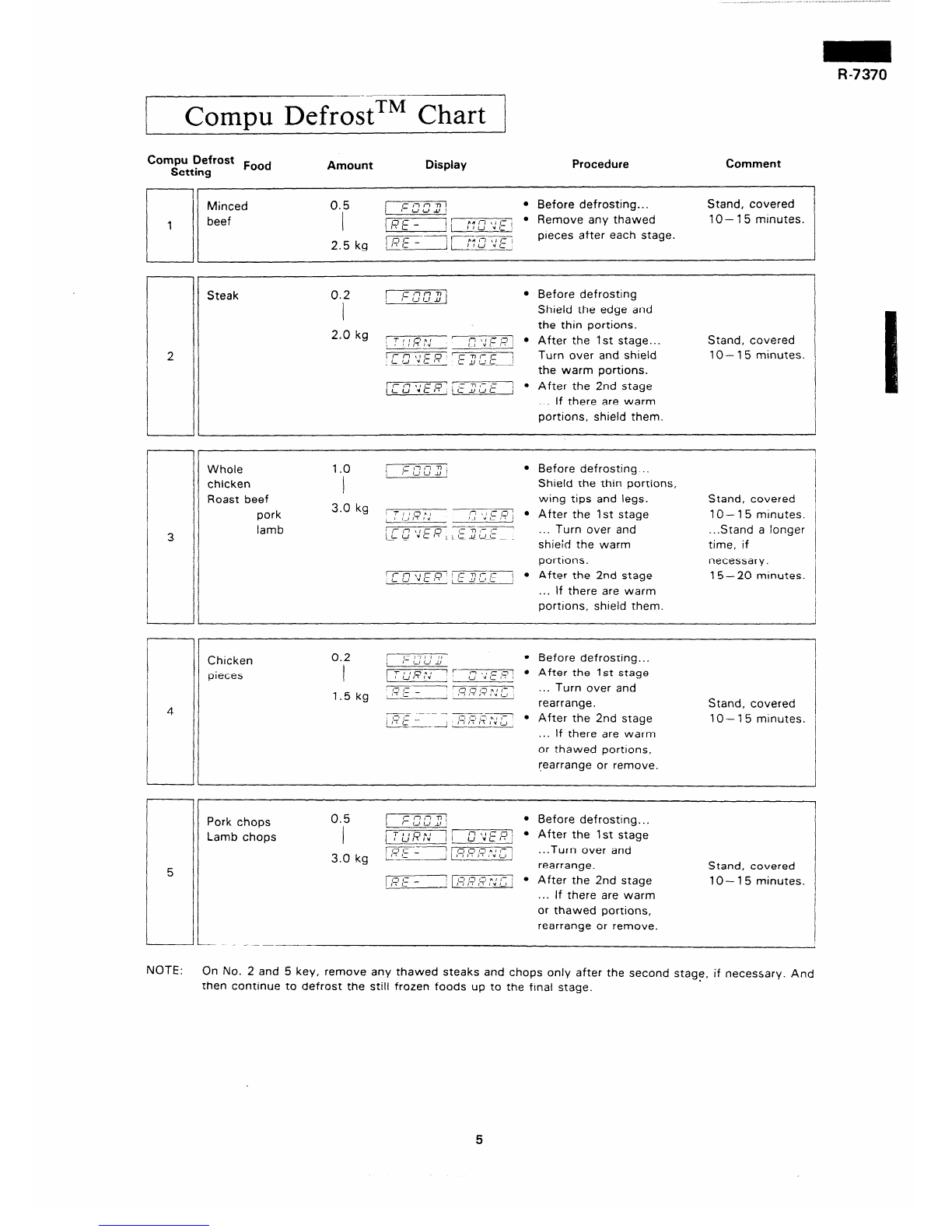
Compu DefrostTM Chart
Compu Defrost Pood
Setting Amount Display Procedure Comment
7
Minced
beef
0.5 r r ii r-7T1I
I- CJLJJJ/ l Before defrosting.. . Stand, covered
I ICE - 1r
i r*n \,,-,
1I1-l Yc l Remove any thawed 10 - 15 minutes.
2 5 kg \Fijf:;7“::‘; pieces after each stage.
L
Steak 0.2 1 :=&Tu”] l Before defrosting
I Shield the edge and
2.0 kg , the thin portions.
T : I f-rAI
: , l-7\ , /- n
-81-T’” IJ ”1:87
1 l After the 1st stage...
x
, I- nticO 1
c-nit= I Turn over and shield
L ‘J ” ,- I* i LI1-li the warm portions.
’ I- 1-l*1C 0 ’ i c I, ,J t
- 7 /- -
LU <Cl’ ,, I l After the 2nd stage
... If there are warm
portions, shield them.
Stand, covered
lo- 15 minutes.
Whole
chicken
Roast beef
pork
lamb
1.0 /- r-ln ii
i- ,J L, JJ l Before defrosting ..
I Shield the thin portions,
3.0 kg 2 wing tips and legs. Stand, covered
Trin*,
2 ,JI?lti ‘7 /, ,- ,I ;
f-1 d,I IL l After the 1st stage 10 - 15 minutes.
lf-~~:E,q. ry-zz---
) 11J.lr-1c’ ... Turn over and ...Stand a longer
shieid the warm time, if
portions. necessary.
/ I- n \, I= 0 117 I- I= ’
i ,J ”L It / a- 1J,-I,- j l After the 2nd stage 15- 20 mtnutes.
... If there are warm
portrons, shield them.
7r 1
Chicken
pieces
0.2
I * r-m : ~~~~~~h”,“f~~~~~~~~
k
1.5 kg ‘:?E - 1213,I n,I- ’ ... Turn over and
f I tI ,\ I”r-, rearrange.
I
I
Stand, covered
i’ ‘- 7=x--Tyy=- .
/,si-- ii r-l IT h ,” ,J After the 2nd stage lo- 15 minutes.
... If there are warm
or thawed portrons,
rearrange or remove.
NOTE:
Pork chops
Lamb chops
0.5 /--T-m-y l Before defrosting...
I ‘1 17klcu’ l
/I UVLI’ , After the 1st stage
3.0 kg /r_7c_i 1,-I n I-’ nI I-
; ,I ,- / / r71: IT I”, I , ...Turn over and
- rearrange. Stand, covered
--
/y ;= - m l After the 2nd stage IO- 15 minutes.
... If there are warm
or thawed portions,
rearrange or remove.
On No. 2 and 5 key, remove any thawed steaks and chops only after the second stage, if necessary. And
then continue to defrost the still frozen foods up to the final stage.
5
REHEAT SENSOR
HOW REHEAT SENSOR WORKS
Sharp’s Electronic Sensory Processor is a semi-conductor device that detects the vapor (humidity) emit-
ted from food as it heats. The Sensor adjusts heating times and variable power for various foods and quan-
tities. It takes the guesswork out of microwave heating.
HERE’S AN EXAMPLE OF HOW IT WORKS: +“c*
1 SENSOR ‘1 0% kc
J ; i f’:’
I
1y&i, ir;‘I/
> \
ek
BROCCOLI
1. Broccoli at room temperature. 2. Heat Broccoli. Vapor is emitted 3. Sensor detects vapor and cal-
Vapor is emitted very slowly. rapidly. culates cooking time and vari-
Before You Use REHEAT SENSOR able power.
1. The oven should not be operated on Sensor Reheat immediately after plugging in the unit. Wait 5
minutes .before using the Sensor Reheat.
2. The Reheat Sensor is designed to work best for reheating precooked foods.
The Reheat Sensor may not work perfectly with all menus. Please refer to Reheat Chart for available
menus.
3. Be sure the exterior of the cooking container and the interior of the oven are dry. Wipe off any moisture
with a dry cloth or paper towel.
4. Room temperature should not exceed 35OC.
5. Dense casseroles are difficult to heat with the Reheat Sensor and may be too cool. Stirring the cas-
serole after heating will help to equalize temperatures.
6. If the Reheat Sensor has not detected the vapor of the food after 15 minutes,, E fFR /I7,?/and LRE -
, HER T jwill appear in the display and the oven will shut off.
Preparing Foods
1. Reheat Sensor works with foods at normal storage temperature. For example, chicken pieces would
be at refrigerator temperature and canned soup at room temperature.
2. A minimum quantity of a half cup should be heated when using the Reheat Sensor. Smaller quantites
should be heated by time and variable power.
3. Should foods be cooler than desired, simply heat an additional minute or two using Instant Cook.
4. If a particular food is hotter than desired, consult your cookbook or cooking guide and choose time
and variable power the next time the food is heated.
5. The arrangement of foods will affect heating results. Place the thickest parts of foods to the outside
of the dish, where they will receive more microwave energy.
6. When possible, stir foods before eating.
Covering Foods
Foods should be covered with plastic wrap or casserole lid when using the Reheat Sensor. Other cover-
ings may cause foods to overheat.
1. Casserole lid.
2. Plastic wraps.
Use plastic wraps recommended for microwave cooking.
Cover dish loosely; fold excess wrap over side of dish.
Do not create an air tight seal, follow procedure in chart.
Be careful when removing any covering to allow steam to escape away from you.
1. Casserole lid 2. Plastic wrap
6
R-7370
To Use Reheat Sensor
To use the Reheat Sensor, open oven door, place food in oven, close door and touch REHEAT SENSOR
pad. REHEAT SENSOR pad must be touched within one minute after closing oven door or touching the
STOP/CLEAR pad.
* Suppose you want to reheat vegetables.
Step Procedure
1. Touch REHEAT SENSOR pad.
Pad Order
I REHEAT
SENSOR 1
Display
I
/ SENSOR
I-i r
i COOK IT I,- -
I
I
I ~~~;~R
COOK
They will be displayed con-
tinuously.
The oven will start operating. When the food is hot as detected by the reheat sensor, all indicators will
go out and an audible signal will sound. The time of day will reappear on the display.
NOTE: Avoid opening the oven door or touching STOP/CLEAR pad when 1?E - : / ,5rE,q T : is dis-
played. if this occurs, / 15R ,?‘,T/?/ andmy/ 8 E R T <will appear and sensor heatingwill be in-
terrupted. To continue heating, touch STOP/CLEAR pad. E/?,??r_7/?:and’r-‘I :-gl~,qT willgo
out. Select heating time and variable power level. Heating with the Reheat Sensor at this point
may result in overheating.
Reheat Chart
FOOD QUANTITY UTENSIL COVER
soup
Dinner Plate
Casserole
Meat Sauce
Canned Food
Steak
Chops
Sliced Roast Beef
Hamburger Patties
Chicken Pieces
Fried Rice
Hot Dog
Sweet Fruit Pie
l-4 cups Casserole Lid or Plastic Wrap
1 serving Plate Plastic Wrap
200-1000 g
200-800 g 11 Casserole Lid or Plastic Wrap
200-1000 g / Mixing bowl Plastic Wrap
1-4 1
l-6 I
200-500 g / i Plate Plastic Wrap
2-6
2 -4 pieces I i
i !
200- 1000 g Mixing Bowl Plastic Wrap
l-2 - Paper Towel
l-4 pieces Plate No
7
R-7370
SERVICING
TROUBLESHOOTING GUIDE
Note: For other Test Procedures, please refer to Service Manual for Base Model R-7260 etc.
PROBLEM POSSIBLE CAUSE TEST PROCEDURE OR
CORRECTION
SENSOR COOKING
Oven is in the sensor cooking con-
dition but RH sensor does not end
stage 1. of cooking cycle, cooking
cycle or does not step cooking
cycle.
RH sensor open and/or short.
Defective control unit
Open or loose wire connection to the above
components.
Procedure M.
Procedure M.
Check and repair wiring.
TEST PROCEDURES (CONT’D)
IKEY UNIT /
PROCEDURE
LETTER COMPONENT TEST
K KEY UNIT TEST
If the Indicator does not respond to touching a key Pad use the following matrix and place a jumper wire
between the proper pin connections with the G (l2-pin) cabie disconnected from the control unit.
If the indicator responds and oven goes into operation, the key unit is faulty.
If there is no response, replace the control unit.
8
R-7370
TEST PROCEDURES (CONT’D)
PROCEDURE
LETTER COMPONENT TEST
M REHEAT SENSOR CIRCUIT
Water Load Cooking Test
Check as follows:
(1) Fill 100 milliliters (3.6 oz) of tap water initially at 20 + 1 OC (68°F) in a 500 milliliter measuring
cup.
(2) Place the container on the center of turntable tray in the oven cavity.
(3) Close the door, and touch “REHEAT SENSOR” pad.
(4) The oven is in the sensor cooking condition.
(5) Sensor cooking time should be 3 min. * 75 seconds.
Checking the Control Unit with Use of Dummy Resistor
(1) Take the procedures according to the instructions in “Servicing of Touch Control Panel”.
Besides it is needed to connect the parts as shown in Fig. A to the connector (C) to enable checking
of the REHEAT SENSOR.
(2) Check the sensor cook operation proceed as follows:
(2-l 1 Touch “REHEAT SENSOR” pad.
(2-2) The control panel is in the sensor cooking operation.
(2-3) After approximately 40 seconds, push plunger of MICRO switch.
This condition is same as judgement by REHEAT SENSOR.
(2-4) After approximately 3 seconds, cooking operation turns off, an audible signal will sound, and the
display will then revert to the time of day.
If the above is not case, the control unit is probably defective.
If the above is proper, the REHEAT SENSOR is probably defective.
MICRO
SWITCH
COM/ 39kn 1/4W &S’rC
* Sensor
CLIP Connector
CONNECTOR on Control
t4!55n tw fS% Panel
0 b - C-f
-c-2
-c-3
Figure A. Sensor Dummy Resistor Circuit
9
R-7370
TOUCH CONTROL PANEL ASSEMBLY
OUTLINE OF TOUCH CONTROL
The touch control section consists of the following units as
shown in the block diagram.
(1) Key unit
(2) Control unit
Exchange of signals between each unit is indicated by the ar-
rows in the block diagram. The principal functions of these
units and the signals communicated among them are explained
below.
l-l. Key Unit
The key unit is composed of a matrix, signals generated
in the LSI are sent to the key unit through P62, P63,
P70 - P73. When a key pad is touched, a signal is com-
pleted through the key unit and passed back to the LSI
through PlO - P13 to perform the function that was
requested.
l-2. Control Unit
Control unit consists of LSI, Power source circuit, Syn-
chronizing signal circuit, ACL circuit, Buzzer circuit,
Reheat sensor circuit and Indicator circuit.
1) Power Source Circuit
This circuit generates voltage necessary in the control
and indicator circuit, from the AC line voltage. In ad-
dition, the synchronizing signal is available in order to
compose a basic standard time in the clock circuit.
2) Synchronizing Signal Circuit
The power source Synchronizing signal is available in
order to compose a basic standard time in the clock
ci rcu it.
It accompanies a very small error because it works on
the commercial frequency.
3) LSI (IX2412YA)
This LSI controls the reheat sensor signal, key touch
and relay control signal for oven function, and control
of the indicator circuit.
4) ACL
A circuit to generate a signal which resets the LSI to
the initial state when power is supplied.
5) Stop switch
A switch to “tell” the LSI if the door is open or closed.
6) Buzzer
The buzzer is responsive to signals from the LSI to
emit noticing sounds (key touch sound and completion
sound).
7) Relay Circuit
To drive the magnetron, fan motor, turntable motor
and light oven lamp.
8) Reheat Sensor Circuit
This circuit detects moisture of a food which is under
cooking, to allow its automatic cooking.
9) Indicator Circuit
This circuit consists of 6-digits, 13 segments display,
five cooking mode indicators.
10
R-7370
.
1
-Q
3
2
.-
z
-
z
;
c
.-
-E
.Z
2
G
2
co
-7
2:
$5
*
t?z
m
.. ‘3;
G?
3-
is
-Jl-
a
>
b 2
~22~2”‘~gg~
aaQanZaen..a CVFOC3N
cnmmccco
QQQQQ
s
Iv
z
2
..
5
-
w
Ti
58
iz
P
5
.
0”
2
c
.-
Q
f
z
d
Q
z
:
.-
s
75
PC
e
I-
t!
33
.-
u.
R-7370
Pin No. Signal Description
Segment data signals
The relation between signals and segments are as follows:
P30
1
2 Signal
P20
P21
P22
P23
P30
P31
Segme
.............. d
.............. C
.............. b
nt
OUT
OUT
OUT
P31
P32
I ‘r-d
;I 1,
: Gw :; II
M:D j; H;);H ,I/ I
P33 . . * . . . . . . *... * a i AUTO 1: II
/I //
-LiB-- ‘/ I ,I LB
,i---4i--_-~~L-----~
j COOK :/
LB ‘I
s............. e
. . * . . ...* . . . . . f
P32 .............. g 1.68 msec.
P33 .............. h --- GND
P40 .............. i a .......... DEFROST Segment
P41 j b .......... SENSOR.............. II--
Signal
P42 .............. k -27V
IN Auto-clear terminal
ACL
CL1
Signal is input to reset the LSI to the initial state when power is supplied. Temporarily set
to “L” level the moment power is supplied, at this time the LSI is reset. Thereafter set at ;
“H” level.
I I
j
6 IN Internal clock oscillation frequency setting input. I
The internal clock frequency is set by inserting the ceramic filter oscillation circuit with i
respect to CL2 terminal.
OUT Internal clock oscillation frequency control output.
Output to control oscillation input of CLl.
CL2
P40 OUT Segment data signal.
Signal similar to P30.
TEST IN Not used. Connected to VDD (-12V).
P41 OUT Segment data signal.
- Signal similar to P30.
OUT
P42
12 P43 OUT Signal for lighting of Power level and COMPU indicators.
Signal similar to P30.
13 P50 OUT Signal for lighting of COOK, AUTO and kg indicators.
Signal similar to P30.
14 P51 IN
-4 Terminal not used. /
/
IN
15 P52
16 IN
IN
Not used. Terminal for manufacture test. 1
17
18
19
P53
P60
I’61
P62
20 P63
I
IN Terminal not used. I
OUT Key strobe signal.
Signal applied to touch-key section.
A pulse signal is input to PlO - P13 terminal while one of G-l line keys on key matrix is
touched.
OUT Key strobe signal.
Signal applied to touch-key section.
A pulse signal is input to PlO - P13 terminal while one of G-2 line keys on key matrix is
touched.
13
R-7370
I
1 23
24 i
1
j 27 t
P71 OUT
P72 OUT
=-I--=
KT IN
KI IN
so OUT
Signal I/O
P70 OUT
28 1 NC NC
29. 1 VDD IN
I
30 P80 OUT
31 P81 IN
32 ( GND IN
33 P82 IN
34 P83 OUT
35 P90 OUT
36 P91 OUT
37 P92 OUT
38 P93 OUT
-r Description
Kev strobe signal.
Signal applied to touch-key section.
A pulse signal is input to PlO - P13 terminal while one of G-3 line keys on key matrix is
touched.
Key strobe signal.
Signal applied to touch-key section.
A pulse signal is input to PlO - P13 terminal while one of G-4 line keys on key matrix is
touched.
Key strobe signal.
Signal applied to touch-key section.
A pulse signal is input to PlO - PI3 terminal while one of G-5 line keys on key matrix is
touched.
Kev strobe signal.
Signal applied to touch-key section.
A pulse signal is input to PlO - P13 terminal while one of G-6 line keys on key matrix is
touched.
Terminal not used.
Sinnal to sound buzzer.
A: Key touch sound.
B: Completion sound. 0.12 sec.
A. -//-
B
l . r
l , l
rZWurrc,i r.L*f -25,“*
T T4oor10-• _
Not used.
Power source voltage: -12V.
VDD Voltage of power source circuit input
Terminal not used.
Connected to GND.
Terminal not used.
Used for initial balancing of the Reheat Sensor circuit
14
R-7370
Pin No. Signal I/O Description
39 PO0 IN RH sensor input.
This input is an analog input terminal from the RH sensor circuit, and connected to the A/D
converter built into the LSI.
40 PO1 IN Terminal to change the functions according to the Model.
By using the A/D converter contained in the LSI (IX2412YA), DC voltage in accordance
with the Model in operation is applied to set up its function.
Not used. Connected to GND.
41 PO2 IN
42 PO3 IN Terminal to change the functions according to the Model.
By using the A/D converter contained in the LSI, DC voltage in accordance with the Model
in operation is applied to set up its function.
43 Signal coming from touch-key.
When either one of G-l 1 line keys on keys on key matrix is touched, a corresponding signal
out of P70 - P73, P63 and P62 will be input into PIO.
When no key is touched, the signal is held at “L” level.
PI0
PI1
IN
IN
44 Signal similar to PlO.
When either one of G-IO line keys on key matrix is touched, a corresponding signal will be
input Pll.
45 P12 IN Signal similar to PlO.
When either one of G-9 line keys on key matrix is touched, a corresponding signal wiil be
input PI 2.
IN
46
47
48
PI3
AGND
Signal similar to PIO.
When either one of G-8 line keys on key matrix is touched, a corresponding signal will be
input P13.
IN Connected to GN D.
Digit selection signal.
The relation between digit signal and digit are as follows:
Digit Signal Digit
PA4 . . . . . . . . . . . 1st
PA5 . . . . . . . . . . . 2nd 1.32 msec.
PA6 . . . . . . . . . . . 3rd
PA7 . . . . . . . . . . . 4th PA4
PA8 . , . . . . . . . . . 5th
PA9 . . . . . . . . . . . 6th
r--------- ;;;”
Normally, one pulse is output in every
I3 period, and input to the grid of the
Fluorescent Display.
PA5 n
PA6 n
PA7 [
PA6 fl
PA9& T:c,
1.32 msec.
15
PA9 OUT
OUT
49 PA8
PA7
50 OUT
OUT
51 PA6
52 PA5 OUT
53 PA4 OUT
R-7370
Pin No. Signal I/O Description
54 PA3 OUT ‘Oven Iamp cooling fan motor and turn table motor driving signal (Square waveform:
50Hz).
To turn on and off the shut-off relay (F$Y I) :
The Square waveform voltage (50Hz) is delivered to the RYI driving circuit and RY2
control circuit. 20 msec.
L- -
----- GND
, L -19v
During cooking or when door is opened.
55 ’ PA2 ’ OUT ’ Magnetron high-voltage circuit driving signal.
To turn on and off the cook relay (RYZ).
In HIGH operation, the signals holds “H” level during microwave cooking and “L” level
while not cooking. In other cooking modes (HIGH, M-HIGH, MED, M-LOW, LOW) the
signal turns to “H” level and “L” level in repetition according to the power level.
HIGH JJ
ME0 HIGH
56
57
58
32 WC. J
I HOLD e-m L
Vdisp IN Anode (segment) of Fluorescent Display light-up voltage: -27V.
Vp voltage of power source circuit input
VR IN Reference voltage input terminal.
A’reference voltage applied to the A/D converter in the LSI.
The reference voltage is generally maintained at -6.15V.
PA1 IN Signal synchronized with commercial source frequency.
This is the basic timing for time processing of LSI (ICI: lX2412YA).
20 msec.
16
R-7370
Pin No. Signal I/O Description
59 PA0 IN Input signal which communicates the door open/close information to LSI.
Door closed: “H” level signal (OV)
Door opened: “L” level signal (-12V)
60 P20
61 P21
OUT Segment data signals.
--- Signal similar to P30.
OUT
62 P22
63 P23
OUT
OUT
I 64 / GND ) IN ) Connected to GND. I
POWER SOURCE CIRCUIT
A power of AC 240V is applied to the primary winding of
transformer (Tl).
The output voltage of the secondary winding of transformer
(Tl) is then full-wave rectified by the diode bridge (Dl) and
smoothed by the electrolytic capacitor (C2) to become DC
voltage VC. Then the voltage VC is delivered to the constant
voltage circuit.
VDD f-12V) is a voltage to be applied to the LSI.
Tl Dl
POWER
SUPPLY
240V 50Hz VRSl
t
To Relay Confact
Figure T-3. Power Source Circuit
17
R-7370
SYNCHRONIZING S
IGNAL CIRCUIT
At the secondary side of the power source circuit there is
caused AC half-wave rectified voltage and it is applied via R7
to PA1 terminal of LSI. This voltage is referred to as a power
sync. signal.
R7 58
> T 1
(gk) R8tt””
**
PA1
LSI I I
I- 20.0 msec. -I
Figure T-4. l3 Circuit and Waveform
ACL CIRCUIT
By switching on power, charge current (il) is fed to C20
through R20 and generates throshold voltage (Vz).
If Vz exceeds the zener voltage of ZD20, ZD20 is turned on
and the current i2 flows. Thus, placing voltage on to the base
of transistor Q20 and turning it on.
A reset signals is obtained from the collector.
C21: Noise filter capacitor.
GND, a
v a--
l 1
RESFT
GND
J RESET
Figure T-5. ACL Circuit
18
R-7370
BUZZER CIRCUIT
The square waveform developed from T terminal of LSI is
applied to the base of Q30 to turn on and off Q30, and square
waveform voltage (2.5 kHz) is applied to SPl to generate
buzzer sound.
030
I- -------l
I ; (From LSL)
SPl Dp~~~“-T-;;y~;
L
----- J
T J
u-uzv
sp]Ga
L-r’:”
Figure T-6. Buzzer Circuit
RELAY CIRCUIT
While the unit is in cook, “H” level signal is produced at
PA2 terminal of LSI and also a pulse signal at PA3 terminal of
LSI. The pulse signal form PA3 terminal is applied to the rec-
tifier circuit made up of Diodes DlOO and DlOl inside the
hybrid IC (IC3) where it is made into DC signal to charge
Cl 00. With Cl00 charged up, 0100 and QlOl turn on in
succession so that a current I1 is caused to turn on the control
relay (RY 1).
The “H” level signal from D6 terminal is applied to Q80 which
is connected in series with QlOl, and current i2 made only
when both Q80 and 0101 are turned on at the same time
allowing the cook relay (RY2) to turn on.
To Power Source Circait
RY2 1
(COOK RELAY)
RYl P
I I j i2
1
R103 0101 Cl01 44h 15
R105
IC3 : Hybrid IC
Figure T-7. Relay Circuit
19

Other manuals for R-7370

1

Other Sharp Microwave Oven manuals

Sharp Carousel R-1405, Carousel R-1406 User manual

Sharp

Sharp Carousel R-1405, Carousel R-1406 User manual

Sharp Carousel RK-42S24 User manual

Sharp

Sharp Carousel RK-42S24 User manual

Sharp SKCD24U0GS User manual

Sharp

Sharp SKCD24U0GS User manual

Sharp R-417DWM User manual

Sharp

Sharp R-417DWM User manual

Sharp R-426H User manual

Sharp

Sharp R-426H User manual

Sharp R-651ZS User manual

Sharp

Sharp R-651ZS User manual

Sharp R-659YW User manual

Sharp

Sharp R-659YW User manual

Sharp Carousel R-1850A User manual

Sharp

Sharp Carousel R-1850A User manual

Sharp R-450C User manual

Sharp

Sharp R-450C User manual

Sharp R-2V53 User manual

Sharp

Sharp R-2V53 User manual

Sharp R-210A User manual

Sharp

Sharp R-210A User manual

Sharp R-202EW User manual

Sharp

Sharp R-202EW User manual

Sharp R-772WM User manual

Sharp

Sharp R-772WM User manual

Sharp Carousel R-230L Use and care manual

Sharp

Sharp Carousel R-230L Use and care manual

Sharp YC-PS204AE User manual

Sharp

Sharp YC-PS204AE User manual

Sharp R-209-A User manual

Sharp

Sharp R-209-A User manual

Sharp R-2235H(R) User manual

Sharp

Sharp R-2235H(R) User manual

Sharp AX-1100 User manual

Sharp

Sharp AX-1100 User manual

Sharp R-290H User manual

Sharp

Sharp R-290H User manual

Sharp R-310FW User manual

Sharp

Sharp R-310FW User manual

Sharp R-272M User manual

Sharp

Sharp R-272M User manual

Sharp R-860M User manual

Sharp

Sharp R-860M User manual

Sharp YC-PS201AE User manual

Sharp

Sharp YC-PS201AE User manual

Sharp R-933 User manual

Sharp

Sharp R-933 User manual

Popular Microwave Oven manuals by other brands

Panasonic NN-CD87KS manual

Panasonic

Panasonic NN-CD87KS manual

Whirlpool GSC309PVS00 Use & care guide

Whirlpool

Whirlpool GSC309PVS00 Use & care guide

Daewoo KOR-6N7RS Operating instructions & cook book

Daewoo

Daewoo KOR-6N7RS Operating instructions & cook book

Steba KB M23 Instructions for use

Steba

Steba KB M23 Instructions for use

GE Spacemaker JVM1540LNCS Dimensions and installation information

GE

GE Spacemaker JVM1540LNCS Dimensions and installation information

Samsung MS32H5125 Series Owner's instructions & cooking guide

Samsung

Samsung MS32H5125 Series Owner's instructions & cooking guide

LG LMA840W Owner's manual & cooking guide

LG

LG LMA840W Owner's manual & cooking guide

GE Appliances CEB1590 owner's manual

GE

GE Appliances CEB1590 owner's manual

Frisch Labor Systems 306000 Instruction

Frisch Labor Systems

Frisch Labor Systems 306000 Instruction

IKEA VÄRMD manual

IKEA

IKEA VÄRMD manual

Toyotomi AG925BLP instruction manual

Toyotomi

Toyotomi AG925BLP instruction manual

Whirlpool MS1600XW Use & care guide

Whirlpool

Whirlpool MS1600XW Use & care guide

Whirlpool g2microven GH9177XL Use & care guide

Whirlpool

Whirlpool g2microven GH9177XL Use & care guide

RCA RMW927 instructions

RCA

RCA RMW927 instructions

Amana 1800 W - 2005 manual&nbsp;

Amana

Amana 1800 W - 2005 manual&nbsp;

Hisense HMO173SR Use and care guide

Hisense

Hisense HMO173SR Use and care guide

privileg TC034B2U-S0EE user manual

privileg

privileg TC034B2U-S0EE user manual

Teka MWR 32 BIA user manual

Teka

Teka MWR 32 BIA user manual

manuals.online logo
manuals.online logoBrands
  • About & Mission
  • Contact us
  • Privacy Policy
  • Terms and Conditions

Copyright 2025 Manuals.Online. All Rights Reserved.