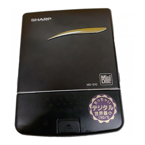
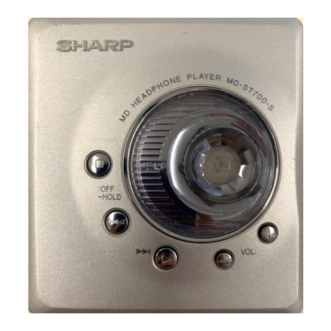
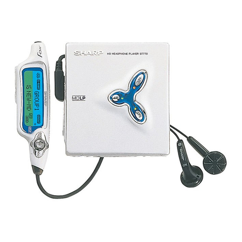
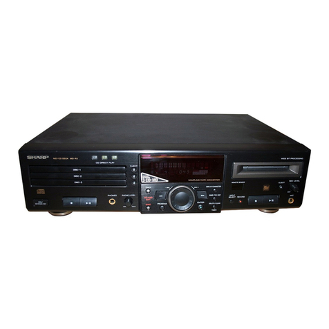
Sharp MD-R2H User manual

MD-R2H
– 1 –
• In the interests of user-safety the set should be restored to its
originalconditionandonlypartsidenticaltothosespecifiedshould
be used.
MD-R2H
CONTENTS Page
SAFETY PRECATION FOR SERVICE MANUAL.................................................................................................................. 2
IMPORTANT SERVICE NOTES (FOR UK ONLY) ................................................................................................................ 3
SPECIFICATIONS ................................................................................................................................................................. 3
NAMES OF PARTS ............................................................................................................................................................... 4
OPERATION MANUAL .......................................................................................................................................................... 5
DISASSEMBLY...................................................................................................................................................................... 8
REMOVING AND REINSTALLING THE MAIN PARTS....................................................................................................... 10
ADJUSTMENT ..................................................................................................................................................................... 12
EXPLANATION OF ERROR DISPLAY................................................................................................................................ 23
EXPLANATION OF MECHANISM ERROR ......................................................................................................................... 24
BLOCK DIAGRAM ............................................................................................................................................................... 28
SCHEMATIC DIAGRAM/WIRING SIDE OF P.W.BOARD................................................................................................... 30
NOTES ON SCHEMATIC DIAGRAM .................................................................................................................................. 43
WAVEFORMS OF MD CIRCUIT .......................................................................................................................................... 44
TROUBLE SHOOTING ........................................................................................................................................................ 46
FUNCTION TABLE OF IC.................................................................................................................................................... 51
PARTS GUIDE/EXPLODED VIEW
PACKING METHOD (FOR UK ONLY)
SERVICE MANUAL
SHARP CORPORATION
No. S0775MDR2H///
This document has been published to be used
for after sales service only.
The contents are subject to change without notice.
• Note for users in UK
Recording and playback of any material may require consent
which SHARP is unable to give. Please refer particularly to the
provisions of Copyright Act 1956, the Dramatic and Musical
Performers Protection Act 1956, the Perfmers Protection Acts
1963 and 1972 and to any subsequent statutory enactments and
orders.

MD-R2H
– 2 –
SAFETY PRECATION FOR
SERVICE MANUAL
WARNINGS
The ael (ACCESSIBLE EMMISSION LEVEL) of the laser
power output is less than class 1 but the laser component is
capable
of emitting radiation exceeding the limit for class 1. Therefore
it is important that the following precautions are observer
during
servicing to protect your eyes against exposure to the laser
beam.
(1) When the unit case cover is removed and LOADING SW
(SW 1956) is turned on and then PLAY SW (SW 1954
mechanism PWB) is turn on in a few second.
The laser will light for several second to detect a disk.
(2)Thelaserpower output ofthepickupunit and replacement
service parts are all factory pre-set before shipment.
Do not attempt to re-adjust the laser pick-up unit during
replacement or servicing.
(3) Under no circumstances stare into the pickup lens at any
time.
(4) If laser optical unit becomes faulty, replace the complete
laser optical unit.
(5)CAUTION-USEofcontrolsoradjustments,orpereformance
ofproceduresother thanthosespecified hereinmayresult
in hazardous radiation exposure.
(For UK)
(Except for UK)
LASER KLASSE 1
LUOKAN 1 LASERLAITE
KLASS 1 LASERAPPARAT
CAUTION -INVISIBLE LASER RADIATION WHEN OPEN AND INTERLOCKS
DEFEATED . AVOID EXPOSURE TO BEAM .
VARNING - OSYNLIG LASERSTRALNING NAR DENNA DEL AR OPPNAD OCH
SPARRAR
AR URKOPPLADE . STRALEN AR FARLIG.
ADVARSEL -USYNLIG LASERSTRALING NAR DEKSEL APNES OG SIKKERHEDSLAS
BRYTES . UNNGA EKSPONERING FOR STRALEN.
VARO! AVATTAESSA JA SUOJALUKITUS OHITETTAESSA OLET ALTTIINA
NAKYMATON LASERSATEILYLLE . ALA KATSO SATEESEN.
VARNING - OSYNLIG LASERSTRALING NAR DENNA DEL AR OPPNAD OCH SPARREN
AR URKOPPLAD . BETRAKTA EJ STRALEN .
ADVARSEL - USYNLIG LASERSTRALING VED ABNING . NAR SIKKERHEDSAFBRYDERE
ER UDE AF FUNKTION . UNDGA UDSETTELSE FOR STRALING .
VAROITUS! LAITTEEN KÄYTTÄMINEN MUULLA KUIN
TÄSSÄ
KÄYTTÖOHJEESSA MAINITULLA TAVALLA SAATTAA
ALTISTAA KÄYTTÄJÄN TURVALLISUUSLUOKAN 1
YLITTÄVÄLLE NÄKYMÄTTÖMÄLLE LASERSÄTEILYLLE.
VARNING - OM APPARATEN ANVÄNDS PÅ ANNAT SÄTT
ÄN I DENNA BRUKSANVISNING SPECIFICERAS. KAN
ANVÄNDAREN UTSÄTTAS FÖR OSYNLIG
LASERSTRÅLNING, SOM ÖVERSKRIDER GRÄNSEN FÖR
LASERKLASS 1.
Laser Diode Properties
Material: GaAIAs
Wavelength: 785 nm
Pulse time: Read mode: 0.8 mW Continuous
Write mode: max 10 mW 0.5 S
min cycle 1.5 S
Repetition

MD-R2H
– 3 –
LINE IN Pin socket Over 680 mVrms 170 mVrms
22 kohms
OPTICAL Square
IN (Optical)
optical
connector
COAXIAL Pin socket 75 ohms 500 mVp-p
(Coaxial)
General
Type: MiniDisc deck
Signle readout: Non-contact, 3-bean semi-conductor
laser pick-up
Audio channels: Stereo 2 channels/monaural
(long-play mode) 1 channel
Frequency response: 4 - 20,000 Hz (+0/-1 dB)
Rotation speed: Approximately 400 to 900 rpm
Error correction: ACIRC (Advanced Cross Interleave
Reed-Solomon Code)
Coding: ATRAC (Adaptive TRansform
Acoustic Coding)
Recording method: Magnetic modulation overwrite
method
Input sockets
Timer/clock
Type: Digital clock with date function
Timer: ON/OFF, once a day
FOR A COMPLETE DESCRIPTION OF THE OPERATION OF THIS UNIT, PLEASE REFER
TO THE OPERATION MANUAL.
SPECIFICATIONS
A/D,D/A converter: 1-bit
Sampling frequency: 44.1kHz
Wow and flutter: Unmeasurable (less than ±0.001%
W.peek)
Signal/noise ratio: 100 dB or better during playback
(line output)
Power source: AC 230 V, 50 Hz
Power consumption: 17 W
Dimensions: Width: 430 mm (16-15/16")
Height: 93 mm (3-11/16")
Depth: 302 mm (11-15/16")
Weight: 3.6 kg (8.0 Ibs)
Output sockets
Remote control
Power: DC 3V ("AA" (UM/SUM-3, R6,
HP-7 or similar) battery included
x 2)
Specifications for this model are subject to change without
prior notice.
IMPORTANT SERVICE NOTES (FOR UK ONLY)
Beforereturning the unit to thecustomer after completion of a
repairoradjustmentit isnecessaryfor thefollowingwithstand
voltage test to be applied to ensure the unit is safe for the
customer to use.
Setting of Withstanding Voltage Tester and set.
Set name set value
Withstanding Voltage Tester
Test voltage 4,240 VPEAK
3,000 VRMS
Set time 6 secs
Set current(Cutoff current) 4 mA
Unit
Judgment
OK: The “GOOD” lamp lights.
NG: The “NG” lamp lights and the buzzor sounds.
SHORT-CIRCUIT
AC POWER
SUPPLY CORD
CONNECT THE PROBE
TO GND TERMINAL
OF PHONO TERMINAL
PROBE
AC
UNIT
WITHSTANDING
VOLTAGE TESTER
+
-
OUT
OF CHASSIS
SCREW
Socket
name Socket
shape Input
impedance Reference
input level Minimum
input level
Socket
name Output
level Load
impedance
PHONES 6.3 mm (1/4") stereo 15 mV 32 ohms
(Headphones)
socket
LINE OUT Pin socket 2 Vrms 50 kohms
OPTICAL
Square optical connector
OUT (Optical)
Socket shape

MD-R2H
– 4 –
NAME OF PARTS
Front panel
1. TOC Indicator: TOC
2. Total Time Indicator
3. Disc Name Indicator
4. Track Name Indicator
5. Data Indicator
6. Level Meter/Character Information Display
7. Recording Level indicator
8. Recording Level Too High Indicator
9. Music Calender
10. More Tracks Indcator
11. Pause Indicator:
12. Record Indicator:
13. Play Indicator:
14. Monaural Long-Play Mode Indicator
15. Programme Indicator
16. Repeat Indicator:
17. Remaining Time Indicator
18. Random Play Indivator
19. Timer Playback/Timer recording Indicator
20. Clock Indicator
21. Eject Button:
22. Remote Sensor
23. Cue/Review Button:
24. Display/Character Button
25. Name/TOC Edit Button
26. Record Level Control
27. Headphone Level Control
28. Headphone Socket
29. On/Stand-by Button
30. Stop Button:
31. Play/Pause Button:
32. Record Button:
33. Input Select Button
34. Programme Button
35. Jog Dial (Next/Previous)
36. Enter Button
37. Delete/Clear/Timer Button
TOC
12
4 0dB OVERDISC
TRACK
DATE
MONO LP PRGM RANDOM
TIMER REC CLOCK
AM
PM
REMAIN
TOTAL
1234567
8 9 10 11 12 13
15 16 17 18 19 20 14
12345 6 7
8
9
10
11
14 1516 1817 19 20
21 22 23 24 25 26
27
28
29 30 31 32 33 34 35 36 37
12
13
Rear panel
1. AC Power Lead
2. Coaxial Input Socket
(Digiral)
3. Optical Input/Output Sockets
(Digital)
4. Line Input/Output Sockets
(Analogue)
5. Reset Button
12345

MD-R2H
– 5 –
OPERATION MANUAL
Names of controls
1. Remote Control Transmitter Window
2. Direct Key Buttons
3. Play Mode Button
4. Music Scan Button
5. Input Select Button
6. Display Button
7. Time Button
8. Auto Mark Button
9. Track Down/Review Button:
10. Track Up/Cue Button:
11. On/Stand-by Button
12. Programme Button
13. Clear Button
14. Synchro Record Button:
15. Record Cancel Button
16. Record Mode Button
17. Record Button:
18. Play/Pause Button:
19. Stop Button:
1
12
13
14
15
16
17
18
19
2
3
4
5
6
7
8
9
10
11
SETTING THE CLOCK
When recording, the date and time are recorded on the Minidisc.
Setting the date
1
Press the ON/STAND-BY button to turn the power on and
press the TIMER button.
2
Within 10 seconds, turn the jog dial until “TIME ADJUST”
appears.
3
Within 10 seconds, press the ENTER button.
The unit will enter the date setting mode.
4
Set the “year” using the jog dial.
When you turn the jog dial and let go, the year will change
up or down by one.
The year 2000 or later is set as follows:
[00] indicates the year 2000
[01] indicates the year 2001
The range of dates that can be entered is from January 1,
1997 to December 31, 2099.
5
Press the ENTER button to set the “year”.
6
Set the “month” repeating steps 4 and 5.
7
Set the “day” repeating steps 4 and 5.
The unit will enter the time setting mode.
ENTER
DELETE/CLEAR
TIMER
ON/
STAND-BY
DATE
CLOCK
CLOCK
CLOCK
7
6
5
4
3
2
1
Date setting mode
Each time the button is pressed,
the display will change.
Time setting mode

MD-R2H
– 6 –
(Continued)
Setting the time
After step 7, described in the “Setting the date” section
8
Set the “hour” using the jog dial.
When you turn the jog dial and let go, the hour will change
up or down by one. When you turn and hold it, the hour will
change continuously.
The clock uses the 24-hour system.
9
Press the ENTER button to set the “hour”.
10
Adjust the “minute” using the jog dial.
11
Press the ENTER button to set the “minute”.
When the ENTER button is pressed, the clock will show the
correct time.
Checking the date and time
After pressing the TIMER button, turn the jog dial until the date
and time are displayed.
Resetting the date and time
See “Setting the clock”.
Once you have set the date and time, “TIME ADJUST” will
not be displayed in step 2. Turn the jog dial to make the date
and time appear.
If you don't need to change the settings, just press the ENTER
button without turning the jog dial again.
DELETE/CLEAR
TIMER
ENTER
DATE
CLOCK
DATE
CLOCK
DATE
CLOCK
DATE
CLOCK
8
9
10
11
SYMPTOM POSSIBLE CAUSE REMEDY
TROUBLESHOOTING
If a problem occurs
If this unit functions abnormally during operation, first check the following items. If the unit continues to function abnormally,
or if an abnormality appears other than listed below, turn off the player's power and disconnect the AC power plug, then
consult your SHARP dealer or service personnel.
General
SYMPTOM POSSIBLE CAUSE REMEDY
The clock is wrong. Did a power failure occur? Try setting it again.
When a button is pressed, the unit
does not respond. Turn the power off and on again, and
then retry the operation.
Radios make unusual noise or the pic-
ture on the TV screen is distorted. When a radio or TV which uses an
indoor aerial is placed near the unit,
the picture on the TV screen may be
distorted or the radio may not function
properly.
It is recommended that you use an
outdoor aerial.
Audio
A recording cannot be made. Is the MiniDisc protected against ac-
cidental erasure? Slide the accidental erase prevention
tab back to its original position.
Did you try to make recording on a
playback-only MiniDisc? Replace it with a recordable disc.
Can you see the “TOC FULL” mess-
age in the display? Put in another recordable disc with
recording space on it.
Even though a disc has been loaded,
“NO DISC” or “Error” is displayed. Is the disc scratched?
Is the unit located near excessive vi-
bration?
Replace the disc.
Place the unit on a firm, level surface
free from vibration.
Playback stops in the middle of a
track, or playback is not performed
properly.
Is the unit located near excessive vi-
brations? Place the unit on a firm, level surface
free from vibration.
Playback sounds are skipped. Has condensation formed inside the
unit? Remove the disc and leave the power
turned on. The unit should function
properly in about 1 hour.
Remote control
SYMPTOM POSSIBLE CAUSE REMEDY
The remote control does not function
or does not operate properly. The batteries (polarity) are not inserted
properly. Insert properly.
The batteries inside the remote control
are dead. Replace the batteries.
The remote control is operated from
an incorrect distance or angle. Operate it within a range of 0.2 m (8")
to 6 m (20') and within an angle of 15
o
to either side of centre.
No disc has been loaded. Load a disc.
The power cannot be turned on from
the remote control. Is the AC power lead plugged in? Connect the AC power lead.

MD-R2H
– 7 –
(Continued)
Moisture condensation
In the following cases, condensation may form inside
the unit.
Shortly after turning on a heater.
When the unit is placed in a room where there is ex-
cessive steam or moisture.
When the unit is moved from a cool place to a warm
place.
When the unit has condensation inside, the disc signals
cannot be read, and the product may not function
properly.
If this happens, remove the disc, and open the disc
holder. The condensation should evaporate in approxi-
mately 1 hour. The unit will then function properly.
If a problem occurs
If this product is subjected to strong external inter-
ference (mechanical shock, excessive static electricity,
abnormal supply voltage due to lightning, etc.) or if it
is operated incorrectly, it may malfunction or the display
may not function correctly. If such a problem occurs,
do the following:
Unplug the AC power lead from the AC socket.
Wait about 20 - 30 seconds and then plug the AC power
lead back into the AC socket.
Press the reset button on the back of the unit.
When the reset button is pressed, all of the settings in
memory will be erased.
If strange sounds, smells or smoke come out of the unit
or if a foreign object falls into the unit, turn off the power,
unplug the AC power lead from the AC socket, immedi-
ately. Contact the shop where you purchased the unit.
If a power failure occurs during recording
If the AC power plug is disconnected from the AC socket
or a power failure occurs during recording (before the
TOC information has been recorded on the disc), the
audio portion being recorded at that time will be erased.
When a recording is being added to a MiniDisc which
already has a recording on it, if the TOC is not updated
before the power failure, the added recording will be
erased.
If a power failure occurs or the AC power lead is dis-
connected for about 10 minutes, when power is restored,
the TOC will be written on the disc.
RESET
Pen, pencil, etc.
REMOTE CONTROL
Proper use of the remote control
Aim the remote control at the remote control sensor within 30
o
with no obstacles, and operate as shown.
Notes concerning use:
Replace the batteries if the control distance decreases or
operation becomes erratic.
Periodically clean the transmitter window on the remote
control and the sensor on the main unit with a soft cloth.
Exposing the sensor on the main unit to strong light can
interfere with operation. Change the lighting or the direction
of the unit.
Keep the remote control away from moisture, excessive heat,
shock, and vibrations.
The remote control's usable range is between 0.2 m (8") and
6 m (20') away from the sensor.
15
15
0.2 - 6m (8" - 20')
1
2
3
(Continued)
When an error message is displayed, proceed as follows:
Error messages Meaning Remedy
BLANK MD Nothing is recorded.
(Neither music nor a disc name have been
recorded on this MD.)
Replace the disc with a recorded disc.
Can't COPY You tried to record from a disc which you are
not allowed to copy. Replace it with another disc which you can
copy from (regular CD).
Can't EDIT A track cannot be edited. Change the stop position of the track and then
try editing it.
Can't REC Recording cannot be performed correctly due to
vibration. Move the unit away from the source of vibration.
DEFECT Since this disc has scratches on it, the
recording operation was skipped. Replace the disc with another recordable disc.
Din UNLOCK Incorrect digital signals are input. Connect correct digital signals.
Use the analogue input socket.
DISC ERR The disc is damaged or there is no TOC on the
disc. Reload the disc or replace it.
DISC FULL The disc is out of recording space. Replace the disc with another recordable disc.
FOCUS ERROR The proper focus cannot be obtained. Reload the MiniDisc.
MD ERROR The unit has determined that it is out of order
by performing a self-diagnosis. Ask the store where you purchased this unit,
about repairs.
MECHA ERR* There is a mechanical problem and the disc is
not working properly. Press the ON/STAND-BY button to enter the
stand-by mode, and press the button.
NAME FULL The number of characters for the disc name or
track name exceeds 100. Shorten the disc or track name.
NO DISC A MiniDisc has not been loaded.
The MiniDisc data cannot be read. Load a MiniDisc.
Reload the MiniDisc.
NOT AUDIO The data recorded on this disc is not audio data. Select another track.
Replace the MiniDisc.
PLAYBACK MD You tried to record on a playback-only disc.
The data of disc names and track names are
not able to move from playback-only discs.
Replace it with a recordable MiniDisc.
Edit only the sound.
PROTECTED The MiniDisc is write protected. Move the write protection tab back to its original
position.
TEMP OVER The temperature is too high. Press the ON/STAND-BY button to enter the
stand-by mode, and wait for a while.
TOC ERR* The disc has a large amount of damage.
TOC information cannot be read.
The MD does not meet the specifications for
MDs.
Replace the disc with another disc.
TOC FULL* There is no space left for recording character
information (track names, disc names, etc.) Replace it with another recordable disc.
TOC W ERROR The unit has determined that it is abnormal by
performing a self-diagnosis. Ask the store where you purchased this unit,
about repairs.
U TOC ERR* The TOC information on this disc does not
meet the MD specifications or it cannot be read. Replace it with another disc.
Erase all the data, and try recording.
U TOC W ERR The TOC information could not be created
properly due to a mechanical shock or to
scratches on the disc.
Press the ON/STAND-BY button to enter the
stand-by mode, and try to write the TOC again.
(Remove any source of shock or vibration whilst
writing.)
? DISC The data contains an error. Replace the disc with another disc.
0 0:00 Music is not being recorded. Replace the disc with a recorded disc.
*: Number or symbol
MD-R2H
– 8 –
DISASSEMBLY
Caution on Disassembly
Follow the below-mentioned notes when disassembling
the unit and reassembling it, to keep it safe and ensure
excellent performance:
1. Take the minidisc out of the unit.
2. When disassembling the machine, be sure to withdraw
the power plug from the socket in advance.
3. When disassemble the parts, remove the nylon band or
wire holder as necessary.
Toassemble after repair, besure to arrange thewires as
they were.
If a screw of different length is fitted to the MD mecha-
nism (the screw of the part to be fitted to the MD
mechanism chassis), it may contact the optical pickup,
resulting in malfunction.
4.Whenrepairing,paydueattentiontoelectrostaticcharges
of IC.
1 Top Cabinet 1. Screw .....................(A1) x5 8-1
2 Rear Panel 1. Screw .....................(B1) x5 8-2
3 MD Unit 1. Screw .................... (C1) x4 8-2
2. Flat Cable ...............(C2) x1
3. Socket .................. (C3) x1
4 Front Panel 1. Screw .................... (D1) x5 8-2
2. Flat Cable ...............(D2) x1
3. Socket ................... (D3) x1
5 Main PWB 1. Screw .....................(E1) x6 8-2
(with Transformer)
6 Jog Dial 1. Knob ....................... (F1) x1 8-3
2. Nut .......................... (F2) x1
7 Display PWB 1. Screw .................. (G1) x10 8-3
2. Knob ...................... (G2) x2
3. Socket ................... (G3) x1
8
Headphones PWB
1. Screw .................... (H1) x1 8-3
9 Switch PWB 1. Screw ..................... (J1) x5 8-3
10 MD Mechanism 1. Screw .....................(K1) x4 8-4
Unit
11 MD Main PWB 1. Screw ..................... (L1) x2 9-1
2. Socket .................... (L2) x6
12 MD Mechanism 1. Screw .................... (M1) x4 9-2
REMOVAL PROCEDURE
STEP FIGURE
Figure 8-1
Figure 8-2
Figure 8-3
Top Cabinet
(A1)x1
ø3x10mm
(A1)x1
ø3x10mm
(A1)x3
ø3x10mm
(G1)x10
ø3x10mm(J1)x5
ø3x10mm
Display PWB
Switch PWB
Headphone
PWB
(G3)x1
(H1)x1
ø3x10mm
(F1)x1
(F2)x1
(G2)x2
washer
Front
Panel
Front Panel
Rear Panel
(B1)x5
ø3x10mm
(E1)x2
ø4x8mm
(D1)x1
ø3x8mm
(E1)x3
ø3x10mm
(E1)x1
ø3x10mm
(C1)x4
ø3x6mm
(D1)x1
ø3x8mm
(D1)x3
ø3x8mm
MD Unit
Main PWB
(C3)x1
(D3)x1
(C2)x1
(D2)x1
Washer
Shield Case
(K1) x 2
ø3 x 6mm
(K1) x 2
ø3 x 6mm
MD Mechanism
Unit
Figure 8-4

MD-R2H
– 9 –
Figure 9-2
Figure 9-1
Figure 9-3
MD Main PWB
(L2)x1
Pull
Pickup Flexible
PWB (*1)
Frame
( L2 ) x 1
( L2 ) x 3
( L2 ) x 1
( L1 ) x 4
ø1.7 x 3mm
(*1) After disconnecting the optical
pickup flex PWB from the
connector wrap the front end of
flex PWB in conductive aluminium
foil so as to prevent electrostatic
damage of optical pickup.
(M1)x4
ø1.7x8.9mm
MD Mechanism
• Jog knob replacement procedure
Jog Knob
Jog Decoration
Figure 9-4
Figure 9-5
Display PWB
Remove the pawl of jog decoration with fine piece
such as tweezers, press, and remove the jog knob
with jog decoration.
Remove the pawl of jog decoration
with fine piece such as tweezers,
press, and remove the jog knob with
jog decoration.
Jog Decoration
Jog Knob
FL Window
Front Panel
Display PWB

MD-R2H
– 10 –
REMOVING AND REINSTALLING THE MAIN PARTS
MD MECHANISM SECTION
Performsteps1to 3ofthedisassemblymethodtoremovethe
MD mechanism.
How to remove the magnetic head
(See Fig. 10-1)
1. Remove the screws (A1) x 1 pc.
Caution:
Takeutmostcaresothatthemagneticheadisnotdamaged
when it is mounted.
How to remove the cartridge holder
(See Fig. 10-2)
1. Open the rpller arm lever in the arrow direction, and lower
the clamper lever to the rear side.
2. Apply +5V to the red line side of blue connector of loading
motor,pushtherackgearinthearrowdirectiontomove the
cam plate lever until tick is heard.
3. Remove the screw (B1) x1 pc., and the spring (B2) x1 pc.,
fitted to the holder arm, and shift the cartridge holder to the
left side to remove it.
How to remove the mechanism switch PWB
(See Fig. 10-3)
1. Remove the screws (C1) x 2 pcs., and remove the mecha-
nism switch PWB.
Figure 10-1
Figure 10-2
Figure 10-3
MD Mechanism
(A1)x1
ø1.7x5mm
Magnetic Head
Slider Lever
Cartridge Holder
Clampa Lever
Lack Gear
Roller Arm Lever
Loading Motor
Cam Plate Lever
(B1) x1
Ø1.7x5mm
(B2) x1
(C1)x1
Ø1.7x3mm
(C1)x1
Ø1.7x9.5mm
MD Mechanism
Switch PWB

MD-R2H
– 11 –
How to remove the sled motor/loading motor
(See Fig. 11-1)
1. Remove the screws (D1) x 1 pcs., and remove the sled
motor/loading motor.
Caution:
Be careful so that the gear is not damaged.
(The damaged gear emits noise during searching.)
Figure 11-1
Figure 11-2
Figure 11-3
How to remove the spindle motor
(See Fig. 11-2)
1. Remove the screws (E1) x 3 pcs., and remove the spidle
motor.
Caution:
Be careful so that the turntable is not damaged.
How to remove the optical pickup
(See Fig. 11-3)
1. Remove the screws (F1) x 3 pcs.
Caution:
Be careful so that the gear is not damaged.
(The damaged gear emits noise during searching.)
Sled Motor
Loading
Motor
(D1)x2
Ø1.7x2mm (D1)x2
Ø1.7x2mm
Spindle Motor
Turntable
(E1)x3
Ø1.7x2.5mm
Optical Pickup
(F1)x3
Ø1.7x9.5mm

MD-R2H
– 12 –
ADJUSTMENT
TEST MODE
1) Mode there are 5 kinds TEST MODE as below.
MODE PUSH KEY
A) MD TEST MODE ENTER PLAY
B) AUDIO TEST MODE CUE REVIEW
C) KEY TEST MODE CUE ENTER
D) RECORDING TEST MODE ENTER REC
E) MD TEST2 MODE (DATA MONITOR MODE) ENTER STOP
2) How to start and quit TEST MODE.
AC Supply On or push RESET KEY after push two keys.
In all TEST MODE. Power Off (POWER KEY) is quit TEST MODE.
3) TEST MODE description.
A) MD TEST MODE (ENTER+PLAY)
Disp. Will be "AUT YOBI". In this mode push PLAY KEY in mean product alignment's auto adjust mode.
(Disp. Will be "AUTO AJST". In this mode push PLAY KEY in mean auto adjust mode by disc condition.
Then push PLAY KEY again. It start play and display will be "a__C__". The 4 digits after "a" are address.
After "C" are error rate.)
PUSH KEY NAME ACTION
ENTER Servo adjust mode or menu from adjust mode.
TIMER REC. and P.B. mode or to menu from REC.mode.
NAME Other menu select.
REC Reverse menu select.
PLAY Selected menu execution.
STOP Execute stop.
CUE Slide motor (PIC) move to out-side.
REVIEW Slide motor (PIC) move to in-side.
JOG. UP *1 Manual alignment +1, loading motor on (OUT).
JOG. DOWN *1 Manual alignment -1, loading motor on (IN).
POWER Test mode quit and power off.
EJECT Disc eject.
*1. Jog. Up/Jog. Down key effect for loading motor control when display panel "tsm____e__". (Push STOP KEY some times
to disp. "tsm____e__".)
NOTE. MD test are necessary mode only for MD Unit.
B) Audio test mode (CUE+REVIEW)
This mode is key examination mode for a set with in MD-unit.
Automatically set recording mode.
Digital opt. Digital coax and analog are effective.
Test mode start is REC KEY push after disc toc. Read.
REC KEY push
1) Record form analog function by 3 sec time.
2) Record form digital opt. Function by 3 sec time.
3) Record from digital coax. Function by 3 sec time.
4) Record stop.
Note. 1) If digital function is din unclock. Skip to follwing next function.
2) Digital synchronize level is -50 dB.
Analog synchronize level is -47 dB.
C) Key test mode (CUE+ENTER)
This mode is key examination mode for a set with out MD-unit.
This mode indicate destination as below dot display.

MD-R2H
– 13 –
KEY NAME ILLUMINATE
SEGMENT
TIMER 10 ROW DOT INPUT SELECT TOC
DISPLAY 11 ROW DOT EJECT 7 ROW DOT
REVIEW ALL PLAY 4 ROW DOT
CUE PM STOP 5 ROW DOT
ENTER 8 ROW DOT REC 6 ROW DOT
JOG. UP 17 (M.C.) NAME 9 ROW DOT
JOG. DOWN 18 (M.C.) TIME AM
PROGRAM PRGM
KEY TEST
KEY NAME ILLUMINATE
SEGMENT
D) Recording test mode (ENTER+REC)
This mode is auto recording repeat mode.
After disc full. Erase all and rec start again.
1. Preparation for adjustment
Test disc
MD SECTION
Type Test disc Part No.
1 High reflection disc TGYS1 (SONY) RRCDT0101AFZZ
2 Low reflection disc Recording minidisc UDSKM0001AFZZ
3 Head Adjusting transparent RRCDT0103AFZZ
Extension Cable (See Fig. 26-4)
Type Part No.
1 Extension PWB for servicing RUNTK0457AFZZ
2 Extension Connector (2 Pin) QCNWK0059AFZZ
3 Extension Connector (6 Pin) QCNWK0107AFZZ
4 Extension Cable (5 Pin) QCNWK0109AFZZ
3 Extension Cable (28 Pin) QCNWK0108AFZZ
2. Test mode
Test mode setting method
1. Holding down the ENTER button and MD (PLAY/PAUSE) button, press the RESET button.
(State A is changed to state B .)
2. Insert the playback disc 1 (high reflection disc) or recording disc 2 (low reflection disc). (State C is set.)
Thus, the test mode state is set.
A tsm e : TEST MODE represents version of MD microcomputer.
TEST STOP state (When the MD (STOP) button is ressed in the C state, the indication A
is restored. To restore C again, press the ENTER button.)
B EJECT
TEST
C AUTO
TEST
Entering the specific mode
Whenever the CD (PLAY/PAUSE) button is pressed, the mode is changed.
AUTO pre-adjustment AUTO adjustment RESULT SUB RESULT
EEPROM setting MANUAL adjustment MANUAL pre-adjustment
• Canceling the test mode
When the POWER button is pressed, the test mode is canceled, and the POWER OFF state is set.

MD-R2H
– 14 –
• Test Mode
1. AUTO pre-adjustment mode • Automatic pre-adjustment is performed. (After adjustment the grating adjustment mode is set.)
• The adjustment value is output with the aid of system controller interface.
2. AUTO adjustment mode • Automatic adjustment is performed.
• The adjustment value is output with the aid of system controller interface.
• Continuous playback is performed. (Error rate indication, jump test)
3. RESULT sub-mode • The measurement value, set value and calculated value are indicated.
• The set value is changed manually (in servo OFF state).
4. RESULT mode (final adjustment) • The set value (after calculation) is indicated.
• The set value is changed manually (in servo OFF state).
5. MANUAL pre-adjustment mode • RF side manual adjustment is performed.
• Focus and tracking signal ATT manual adjustment is performed.
• Focus and tracking signal offset setting is performed.
6. MANUAL adjustment mode • Focus and tracking signal ATT manual adjustment is performed.
7. EEPROM setting mode • Various coefficients of digital servo are changed manually.
• Each servo is set to ON individually.
• Temperature detection terminal voltage is measured, and the reference value is determined.
8. TEST-PLAY mode • Continuous playback from the specified address is performed.
• C1 error rate measurement, ADIP error rate measurement.
9. TEST-REC mode • Continuous recording from the specified address is performed.
• Change of record laser output (servo gain is also changed according to laser output)
10. INNER mode • The position where the INNER switch is turned on is measured.
11. EJECT mode • TEMP setting (of EEPROM setting)
• CONTROL setting (of EEPROM setting)
• Setting of laser power (record/playback power)
1. AUTO pre-adjustment mode (Low reflection disc only)
Step No. Setting Method Remarks Display
Step 1 Testmode STOP state [ t s m e ]
Step 2 Press once the ENTER button. AUTO pre-adjustment menu [ A U T O ]
Step 3 Press once the MD PLAY button. The slide moves to the innermost periphery, and automatic [ : _ _ _ _ _ _ ]
pre-adjustment is started.
• During automatic adjustment changes as follows.
HAo→RFg→SAg→SBg→PTG→PCH→GTG→GCH→RCG→
SEG→RFG→SAG→HAO→HEO→TCO→LAO
End of adjustment If adjustment is OK, Step 4.
If adjustment is NG, Step 5.
Step 4 Grating adjustment, [ _ C O M P L E T E _ ]
adjustment value output
Press once the MD STOP button. STEP 2
Step 5 Adjustment value output [ C a n ' t _ A D J . ]
Press once the MD STOP button. STEP 2 AUTO pre-adjustment menu
• : Adjustment name, : Address

– 15 –
MD-R2H
Step 1 Testmode STOP state [ t s m e ]
Step 2
Press the ENTER button three times.
RESULT sub-menu [ _ R S T _ Y O B I _ ]
Step 3 Press once the MD PLAY button. Indication of measurement value [ R F G : _ _ _ ]
Step 4 Press once the ENTER button. Indication of measurement value [ R C G : _ _ _ ]
Step 5 Press once the ENTER button. Indication of measurement value [ R T G : _ _ _ _ _ ]
Step 6 Press once the ENTER button. Indication of measurement value [ G T G : _ _ _ _ _ ]
Step 7 Press once the ENTER button. Indication of measurement value [ P C H : _ _ _ _ ]
Step 8 Press once the ENTER button. Indication of measurement value [ G C H : _ _ _ _ ]
Step 9 Press once the ENTER button. Indication of measurement value [ S A G : _ _ _ ]
Step 10 Press once the ENTER button. Indication of measurement value [ S B G : _ _ _ ]
Step 11 Press once the ENTER button. Indication of measurement value [ S E G : _ _ _ ]
Step 12 Press once the ENTER button. Indication of measurement value [ S F G : _ _ _ ]
Step 13 Press once the ENTER button. Indication of measurement value [ H A O : _ _ _]
Step 14 Press once the ENTER button. Indication of measurement value [ H B O : _ _ _]
Step 15 Press once the ENTER button. Indication of measurement value [ H E O : _ _ _]
Step 16 Press once the ENTER button. Indication of measurement value [ H F O : _ _ _]
Step 17 Press once the ENTER button. Indication of measurement value [ L A O : _ _ _]
Step 18 Press once the ENTER button. Indication of measurement value [ L B O : _ _ _]
Step 19 Press once the ENTER button. Indication of measurement value [ L E O : _ _ _]
Step 20 Press once the ENTER button. Indication of measurement value [ L F O : _ _ _]
Step 21 Press once the ENTER button. Indication of measurement value [ T C O : _ _ _ _]
Step 22 Press once the ENTER button. Indication of adjustment error sequence No. [ Y O B : _ _ _ _]
Step 23 Press once the ENTER button. Indication of adjustment status [ D I F : _ _ _ _]
Step 24 Press once the ENTER button. Indication of pre-adjustment not completed (00)/completed (4B) [ A D J : _ _ _ _]
Step 25 Press once the MD STOP button. RESULT sub-menu state [ _ R S T _ Y O B I _ ]
2. AUTO adjustment mode
Step No. Setting Method Remarks Display
Step 1 Testmode STOP state [ t s m e ]
Step 2
Press the ENTER button two times.
AUTO adjustment menu [ A U T O _ A J S T _ ]
Step 3 Press once the MD PLAY button. The slide moves to the innermost periphery, and automatic [ : _ _ _ _ _ _ ]
adjustment is started.
• In case of high reflection disc changes as follows.
PEG→HAG
•In case of low reflection disc changes as follows.
PEG→LAG→GCG→GEG→LAG
End of adjustment If adjustment is OK, Step 4.
If adjustment is NG, Step 7.
Step 4 Adjustment value output [ _ C O M P L E T E _ ]
Press the MD PLAY button. STEP 5
Press the MD STOP button. STEP 2
Step 5 Continuous playback (pit section) [ s c ]
Continuous playback (groove section)
[ a c ]
Step 6 Press the DISPLAY button. Continuous playback (groove section) [ a a ]
Press the MD STOP button. STEP 2 AUTO adjustment menu
Step 7 Adjustment value output [ C a n ' t _ A D J . ]
Press the MD STOP button. STEP 2 AUTO adjustment menu
• : Adjustment name, : Measurement value, : Address
3. RESULT sub-mode
Step No. Setting Method Remarks Display
• : Measurement value, : Adjustment value, : Other various informations
• ressing the REC button causes reversing.
• When the jog key is turned upward while the setting is displayed, the setting increases, and a new setting is stored in RAM.
• When the jog key is turned downward while the setting is displayed, the setting increases, and a new setting is stored in RAM.

MD-R2H
– 16 –
Step 1 Testmode STOP state [ t s m e ]
Step 2
Press the ENTER button four times.
RESULT menu [ _ R S T U L T _ _ _ ]
Step 3 Press once the MD PLAY button. Indication of set value [ H A G : _ _ _ ]
Step 4 Press once the ENTER button. Indication of set value [ H B G : _ _ _ ]
Step 5 Press once the ENTER button. Indication of set value [ L A G : _ _ _ ]
Step 6 Press once the ENTER button. Indication of set value [ L B G : _ _ _ ]
Step 7 Press once the ENTER button. Indication of set value [ P E G : _ _ _ ]
Step 8 Press once the ENTER button. Indication of set value [ P F G : _ _ _ ]
Step 9 Press once the ENTER button. Indication of set value [ G E G : _ _ _ ]
Step 10 Press once the ENTER button. Indication of set value [ G F G : _ _ _ ]
Step 11 Press once the ENTER button. Indication of set value [ G C G : _ _ _ _ ]
Step 12 Press once the MD STOP button. RESULT menu state [ _ R E S U L T _ _ _ ]
3. RESULT mode (final adjustment)
Step No. Setting Method Remarks Display
• : Measurement value
• ressing the REC button causes reversing.
• When the jog key is turned upward while the setting is displayed, the setting increases, and a new setting is stored in RAM.
• When the jog key is turned downward while the setting is displayed, the setting increases, and a new setting is stored in RAM.
Step 1 Testmode STOP state [ t s m e ]
Step 2
Press the ENTER button five times.
MANUAL auxiliary adjustment mode [ _ M N U _ Y O B I _ ]
Step 3 Press once the MD PLAY button. Initial setting →Temperature measuring mode [ T M P : _ _ _ _ ]
Step 4 Press once the ENTER button. Offset "0" setting →A signal offset tentative measurement [ H A o : _ _ _ ]
Step 5 Press once the ENTER button. B signal offset tentative measurement [ H B o : _ _ _ ]
Step 6 Press once the ENTER button. E signal offset tentative measurement [ H E o : _ _ _ ]
Step 7 Press once the ENTER button. F signal offset tentative measurement [ H F o : _ _ _ ]
Step 8 Press once the ENTER button. Offset tentative measurement →Laser ON [ L O N : _ _ _ _ _ _ ]
Step 9 Press once the ENTER button. Innermost periphery move →RF side FG rough adjustment [ R F g : _ _ ]
Step 10 Press once the ENTER button. Focus ATT (A signal) tentative setting [ S A g : ]
Step 11 Press once the ENTER button. Focus ATT (B signal) tentative setting [ S B g : ]
Step 12 Press once the ENTER button. RF side pit section TG adjustment [ P T G : _ _ ]
Step 13 Press once the ENTER button. Pit section COUT level setting [ P C H : _ ]
Step 14 Press once the ENTER button. Outer periphery move →RF side groove TG adjustment [ G T G : _ _ ]
Step 15 Press once the ENTER button. Groove section COUT level setting [ G C H : _ ]
Step 16 Press once the ENTER button. RF side TCRS adjustment [ R C G : _ _ ]
Step 17 Press once the ENTER button. Tracking ATT (A signal) setting [ S E G : ]
Step 18 Press once the ENTER button. Tracking ATT (B signal) setting [ S F G : ]
Step 19 Press once the ENTER button. Indication of tracking EFMIO measurement [ g M I : _ _ _ ]
Step 20 Press once the ENTER button. RF side pit section FG adjustment [R F G : _ _ ]
Step 21 Press once the ENTER button. Focus ATT (A signal) setting [ S A G : ]
Step 22 Press once the ENTER button. Focus ATT (B signal) setting [ S B G : ]
Step 23 Press once the ENTER button. Offset "0" setting →A signal offset measurement [ H A O : _ _ _ ]
Step 24 Press once the ENTER button. B signal offset measurement [ H B O : _ _ _ ]
Step 25 Press once the ENTER button. E signal offset measurement [ H E O : _ _ _ ]
Step 26 Press once the ENTER button. F signal offset measurement [ H F O : _ _ _ ]
Step 27 Press once the ENTER button. TCRS signal offset measurement [ T C O : _ _ _ ]
Step 28 Press once the ENTER button. A signal offset measurement [ L A O : _ _ _ ]
Step 29 Press once the ENTER button. B signal offset measurement [ L B O : _ _ _ ]
Step 30 Press once the ENTER button. E signal offset measurement [ L E O : _ _ _ ]
Step 31 Press once the ENTER button. F signal offset measurement [ L F O : _ _ _ ]
5. MANUAL auxiliary adjustment mode (only low reflection disc)
Step No. Setting Method Remarks Display
• : Measurement value, : Set value, : Account value

– 17 –
MD-R2H
• If the jog key upward/downward is pressed during setting indication, the setting increases/decreases, and the new setting is stored in RAM.
• If the REC button is pressed, the setting returns step by step excepting the following case.
A signal offset (HAO) →Offset tentative setting →RF side FG adjustment (RFG)
RF side TCRS adjustment (RCG) →RF side groove TG adjustment (GTG)
RF side groove TG adjustment (GTG) →Innermost periphery move →RF side pit section adjustment (PTG)
RF side pit TG adjustment (PTG) →RF side FG rough adjustment (RFg) → Laser lighting (LON)
Laser lighting (LON) →Offset "0" setting →A signal offset tentative measurement (HAo)
If the measurement value is within the OK range, " " appears on the 8th character.
Step 1 Testmode STOP state [ t s m e ]
Step 2
Press the ENTER button six times.
MANUAL adjustment menu [ _ M N U _ A J S T _ ]
Step 3 Press once the MD PLAY button. Initial setting →Temperature measuring mode [ T M P : _ _ _ _ ]
Step 4 Press once the ENTER button. Laser ON [ L O N : _ _ _ _ _ _ ]
Step 5 Press once the ENTER button. Innermost periphery move →Tracking ATT (E signal) setting [ P E G : ]
Step 6 Press once the ENTER button. Tracking ATT (F signal) setting [ P F G : ]
Step 7 Press once the ENTER button. Indication of tracking EFMIO measurement [ P M I : _ _ _ ]
Step 8 Press once the ENTER button. Focus ATT (A signal) setting [ H A G : ]
Step 9 Press once the ENTER button. Focus ATT (B signal) setting [ H B G : ]
6. MANUAL adjustment mode
High reflection disc
Step No. Setting Method Remarks Display
•If the MD STOP button is pressed while the MANUAL adjustment menu is displayed, the state is changed to the TEST mode STOP
state.
• If the REC button is pressed, the setting returns step.
Step 1 Testmode STOP state [ t s m e ]
Step 2
Press the ENTER button six times.
MANUAL adjustment menu [ _ M N U _ A J S T _ ]
Step 3 Press once the MD PLAY button. Initial setting →Temperature measuring mode [ T M P : _ _ _ _ ]
Step 4 Press once the ENTER button. Laser ON [ L O N : _ _ _ _ _ _ ]
Step 5 Press once the ENTER button. Innermost periphery move →Tracking ATT (E signal) setting [ P E G : ]
Step 6 Press once the ENTER button. Tracking ATT (F signal) setting [ P F G : ]
Step 7 Press once the ENTER button. Indication of tracking EFMIO measurement (pit section) [ P M I : _ _ _ ]
Step 8 Press once the ENTER button. Focus ATT (A signal) setting [ L A g : ]
Step 9 Press once the ENTER button. Focus ATT (B signal) setting [ L B g : ]
Step 10 Press once the ENTER button. Outside periphery move →Track closs setting [ G C G : ]
Step 11 Press once the ENTER button. Tracking ATT (E signal) setting [ G E G : ]
Step 12 Press once the ENTER button. Tracking ATT (F signal) setting [ P F G : ]
Step 13 Press once the ENTER button. Indication of tracking EFMIO measurement (groove section) [ G M I : _ _ _ ]
Step 14 Press once the ENTER button. Focus ATT (A signal) setting [ L A G : ]
Step 15 Press once the ENTER button. Focus ATT (B signal) setting [ L B G : ]
High reflection disc
Step No. Setting Method Remarks Display
•If the MD STOP button is pressed while the MANUAL adjustment menu is displayed, the state is changed to the TEST mode STOP
state.
• If the REC button is pressed, the setting returns step by step excepting the following case.
Track closs ATT setting (GTG) → Innermost periphery move →Focus ATT (B signal) setting (LBg)
Step 1 Testmode STOP state [ t s m e ]
Step 2
Press the ENTER button seventimes.
EEPROM setting menu [E E P R O M _ S E T]
Step 3 Press once the MD PLAY button. Focus setting menu [ _ _ F o c u s _ _ _ ]
Step 4 Press once the ENTER button. Focus system loop filter gain constant setting [ F G _ _ _ _ _ _ ]
Step 5 Press once the ENTER button. Focus system loop filter f characteristic constant 1 setting [ F F 1 _ _ _ _ _ ]
Step 6 Press once the ENTER button. Focus system loop filter f characteristic constant 2 setting [ F F 2 _ _ _ _ _ ]
Step 7 Press once the ENTER button. FZC oscillation histerisis level setting a [ F Z H L E V _ _ ]
Step 8 Press once the ENTER button. Comparison level setting (normal) in case of FOK generation [ F O K L E V n _ ]
7. EEPROM setting mode
a) Focus setting
Step No. Setting Method Remarks Display

MD-R2H
– 18 –
Step 9 Press once the ENTER button. Comparison level setting in case of FOK generation [ F O K L E V f _ ]
(when focus is "ON")
Step 10 Press once the ENTER button. LPF coefficient setting (normal) in case of FOK generation [ F O K L P F n _ ]
Step 11 Press once the ENTER button. LPF coefficient setting in case of FOK generation [ F O K L P F f _ ]
(when focus is "ON")
Step 12 Press once the ENTER button. Waiting time setting in case of auto-focus retraction [ W A I T f_ _ _ ]
Step No. Setting Method Remarks Display
• : Setting volue
• Pressing the REC button causes reversing.
• When the jog key is turned upward while the setting is displayed, the setting increases, and a new setting is stored in LSI.
• When the jog key is turned downward while the setting is displayed, the setting increases, and a new setting is stored in LSI.
Step 1 Testmode STOP state [ t s m e ]
Step 2
Press the ENTER button seven times.
EEPROM setting menu [E E P R O M _ S E T]
Step 3 Press once the MD PLAY button. Focus setting menu [ _ _ F o c u s _ _ _ ]
Step 4 Press once the ENTER button. Spindle setting menu [ _ S p i n d l e _ _ ]
Step 5 Press once the ENTER button. Spindle system loop filter gain constant setting [ S P G _ _ _ _ _ ]
(Until tracking servo ON)
Step 6 Press once the ENTER button. Spindle system loop filter gain constant setting [ S P G _ i n _ _ ]
(After tracking servo ON, inner periphery)
Step 7 Press once the ENTER button. Spindle system loop filter gain constant setting [ S P G _ m i d _ ]
(After tracking servo ON, center)
Step 8 Press once the ENTER button. Spindle system loop filter gain constant setting [ S P G _ o u t _ ]
(After tracking servo ON, outside periphery)
Step 9 Press once the ENTER button. Spindle system loop filter f characteristic constant 1 setting [ S P 1 _ _ _ _ _ ]
Step 10 Press once the ENTER button. Spindle system loop filter f characteristic constant 2 setting [ S P 2 _ _ _ _ _ ]
Step 11 Press once the ENTER button. Spindle system loop filter f characteristic constant 3 setting [ S P 3 _ _ _ _ _ ]
Step 12 Press once the ENTER button. Spindle system loop filter f characteristic constant 4 setting [ S P 4 _ _ _ _ _ ]
Step 13 Press once the ENTER button. Spindle system loop filter f characteristic constant 5 setting [ S P 5 _ _ _ _ _ ]
Step 14 Press once the ENTER button. Spindle drive output limitter setting [ S P D L I M _ _ ]
b) Spindle setting
Step No. Setting Method Remarks Display
• : Setting volue
• Pressing the REC button causes reversing.
• When the jog key is turned upward while the setting is displayed, the setting increases, and a new setting is stored in LSI.
• When the jog key is turned downward while the setting is displayed, the setting increases, and a new setting is stored in LSI.
Step 1 Testmode STOP state [ t s m e ]
Step 2
Press the ENTER button seven times.
EEPROM setting menu [E E P R O M _ S E T]
Step 3 Press once the MD PLAY button. Focus setting menu [ _ _ F o c u s _ _ _ ]
Step 4
Press the ENTER button two times.
Tracking setting menu [ _ T r a c k i n g _ ]
Step 5 Press once the MD PLAY button. Tracking system loop filter gain constant setting [ T G _ _ _ _ _ _ ]
Step 6 Press once the ENTER button. Spindle system loop filter f characteristic constant 1 setting [ T F 1 _ _ _ _ _ ]
Step 7 Press once the ENTER button. Spindle system loop filter f characteristic constant 2 setting [ T F 2 _ _ _ _ _ ]
Step 8 Press once the ENTER button. Setting of tracking system servo mode 4 [ S V C N T 4 _ _ ]
Step 9 Press once the ENTER button. Tracking deceleration pulse level setting (for one line jump) [ T R B L V 0 _ _ ]
Step 10 Press once the ENTER button. Tracking deceleration pulse level setting (for 10 line jump) [ T R B L V t _ _ ]
Step 11 Press once the ENTER button. Tracking kick pulse level setting (for one line jump) [ T R K L V 0 _ _ ]
Step 12 Press once the ENTER button. Tracking kick pulse level setting (for 10 line jump) [ T R K L V t _ _ ]
Step 13 Press once the ENTER button. Tracking drive pulse width setting (for one line jump) [ T D P W o _ _ _ ]
Step 14 Press once the ENTER button. Tracking drive pulse width setting (for 10 line jump) [ T D P W T _ _ _ ]
Step 15 Press once the ENTER button. Tracking slip stop time setting (for one line jump) [ S L C T 0 _ _ _ ]
Step 16 Press once the ENTER button. Tracking slip stop time setting (for 10 line jump) [ S L C T t _ _ _ ]
Step 17 Press once the ENTER button. Tracking slip stop time setting (move) [ S L C T m _ _ ]
c) Tracking setting
Step No. Setting Method Remarks Display

– 19 –
MD-R2H
12.2 ~ 15.8 -3
15.9 ~ 19.6 -2
19.7 ~ 23.2 -1
23.2 ~ 26.8 0
26.9 ~ 30.7 +1
30.8 ~ 34.3 +2
34.4 ~ 37.9 +3
Step 18 Press once the ENTER button. TCRS comparison level 1 for high reflection [ T C R S C I P _ ]
Step 19 Press once the ENTER button. Comparison level in case of COUT generation (playback) [ C O T L V p _ ]
Step 20 Press once the ENTER button. Comparison level in case of COUT generation (pecord) [ C O T L V r _ ]
Step 21 Press once the ENTER button. Auto-move waiting time setting [ W A I T m_ _ _ ]
Step No. Setting Method Remarks Display
d) Sled setting
Step 1 Testmode STOP state [ t s m e ]
Step 2
Press the ENTER button seven times.
EEPROM setting menu [E E P R O M _ S E T]
Step 3 Press once the MD PLAY button. Focus setting menu [ _ _ F o c u s _ _ _ ]
Step 4
Press the ENTER button three times.
Sled setting menu [ _ _ _ S l e d _ _ _ ]
Step 5 Press once the MD PLAY button. Slide system loop filter gain constant setting [ S L G _ _ _ _ _ ]
Step 6 Press once the ENTER button. Slide system loop filter f characteristic constant 2 setting [ S L 2 _ _ _ _ _ ]
Step 7 Press once the ENTER button. Sled output limitter setting [ S L D L I M _ _ ]
Step 8 Press once the ENTER button. Slide servo output dead zone level setting [ S L D L E V _ _ ]
Step 9 Press once the ENTER button. Slide kick pulse level setting (forced move) [ S L K L V k _ _ ]
Step 10 Press once the ENTER button. Slide kick pulse level setting (for 10 lines jump auxiliary use) [ S L K L V t _ _ ]
Step 11 Press once the ENTER button. Slide kick pulse level setting (move) [ S L K L V m _ _ ]
Step No. Setting Method Remarks Display
• : Setting volue
• Pressing the REC button causes reversing.
• When the jog key is turned upward while the setting is displayed, the setting increases, and a new setting is stored in LSI.
• When the jog key is turned downward while the setting is displayed, the setting increases, and a new setting is stored in LSI.
Data correction table
Ambient temperature (°C) Temperature correction EEPROM record value = Microcomputer measurement value +
Correction
* EEPROM record value
Value to be measured by the microcomputer at +25°C
* Microcomputer measurement value
Value to be measured by the microcomputer at specific
temperature
* Correction value
Correction value for conversion to measurement value at
+25°C (see the table shown left)
Temperature
judgment zone
0 -79H~ -10H-3.0 dB 82.2 < [°C] TEMP.OVER
1 -0FH~ -0DH-2.5 dB 71.2 < ~ 82.2 76.7 [°C]
2 -0CH~ -0AH-2.0 dB 60.3 < ~ 71.2 65.8
3 -09H~ -07H-1.5 dB 49.1 < ~ 60.3 54.8
4 -06H~ -05H-1.0 dB 41.8 < ~ 49.1 45.5
5 -04H~ -02H-0.5 dB 30.7 < ~ 41.8 36.2
6 -01H~ 01H0 19.6 < ~ 30.7 25.2
702
H
~ 04H+0.5 dB 8.7 < ~ 19.6 14.2
805
H
~ 07H+1.0 dB -2.3 < ~ 8.7 3.0
908
H
~ 0AH+1.5 dB -13.6 < ~ -2.3 -8.0
10 0BH~ FFH+2.0 dB ~ -13.6
• Temperature table
TEMP • Input temperature correction.
• Correct the TEMP. data according to the PWB ambient temperature, and input it.
• Since the temperature rise causes error of temperature sensing part (RF IC), the following requirements must be observed.
1
Perform the TEST mode without mechanical connection.
2
This operation must be performed quickly after power is supplied.
TEMP. input value Temperature
compensation Temperature
range Center
temperature

MD-R2H
– 20 –
e) TEMP setting
Step 1 Testmode STOP state [ t s m e ]
Step 2
Press the ENTER button seven times.
EEPROM setting menu [E E P R O M _ S E T]
Step 3 Press once the MD PLAY button. Focus setting menu [ _ _ F o c u s _ _ _ ]
Step 4
Press the ENTER button four times.
TEMP setting menu [ _ _ _ T e m p _ _ _ ]
Step 5 Press once the MD PLAY button. TEMP reference value setting [ T E M P _ _ ]
Step No. Setting Method Remarks Display
• : Setting volue, : Measurement value
• When the jog key is turned upward while the setting is displayed, the setting increases, and a new setting is stored in LSI.
• When the jog key is turned downward while the setting is displayed, the setting increases, and a new setting is stored in LSI.
Step 1
EJECT state (or mechanism-less state)
[ _ _ E J E C T _ _ _ ]
Step 2
Press the DELETE/CLEAR button.
TEMP reference value setting [ T E M P _ _ ]
Step No. Setting Method Remarks Display
f) CONTROL setting
Step 1 Testmode STOP state [ t s m e ]
Step 2
Press the ENTER button seven times.
EEPROM setting menu [E E P R O M _ S E T]
Step 3 Press once the MD PLAY button. Focus setting menu [ _ _ F o c u s _ _ _ ]
Step 4
Press the ENTER button five times.
CONTROL setting menu [ _ C o n t r o l _ _ ]
Step 5 Press once the MD PLAY button. CONTROL 1 setting [ C O N T R L 1_ ]
Step 6 Press once the ENTER button. CONTROL 2 setting [ C O N T R L 2_ ]
Step 7 Press once the ENTER button. Setting of spin kick level in MOVE state [ S P K L E V m_ ]
Step 8 Press once the ENTER button. Setting of readjustment interval time (minutes) [ A D J T T M_ _ ]
Step 9 Press once the ENTER button. Setting of equalizer coefficients A and D (high reflection) [ H D E Q A D_ _ ]
Step 10 Press once the ENTER button. Setting of equalizer coefficients A and D (low reflection pit) [ L D E Q A D_ _ ]
Step 11 Press once the ENTER button. Setting of equalizer coefficients A and D (low reflection groove) [ G D E Q A D_ _ ]
Step 12 Press once the ENTER button. Setting of equalizer coefficients B and C (high reflection) [ H D E Q B C_ _ ]
Step 13 Press once the ENTER button. Setting of equalizer coefficients B and C (low reflection pit) [ L D E Q B C_ _ ]
Step 14 Press once the ENTER button. Setting of equalizer coefficients B and C (low reflection groove) [ G D E Q B C_ _ ]
Step 15 Press once the ENTER button. Setting of autolevel slicer gain (high reflection) [ H A L S G_ _ _ ]
Step 16 Press once the ENTER button. Setting of autolevel slicer gain (low reflection pit) [ L A L S G_ _ _ ]
Step 17 Press once the ENTER button. Setting of autolevel slicer gain (low reflection groove) [ G A L S G_ _ _ ]
Step 18 Press once the ENTER button. Setting of autolevel slicer offset (high reflection) [ H A L S O F_ _ ]
Step 19 Press once the ENTER button. Setting of autolevel slicer offset (low reflection pit) [ L A L S O F S_ ]
Step 20 Press once the ENTER button. Setting of autolevel slicer offset (low reflection groove) [ G A L S O F S_ ]
Step No. Setting Method Remarks Display
Step 1
EJECT state (or mechanism-less state)
[ _ _ E J E C T _ _ _ ]
Step 2
Press the NAME/TOC EDIT button.
CONTROL 1 setting [ C O N T R L 1_ ]
Step 3 Press once the ENTER button. CONTROL 2 setting [ C O N T R L 1_ ]
Step No. Setting Method Remarks Display
• : Setting volue
• When the jog key is turned upward while the setting is displayed, the setting increases, and a new setting is stored in LSI.
• When the jog key is turned downward while the setting is displayed, the setting increases, and a new setting is stored in LSI.
• CONTROL 1
Pit 7 : High frequency superposition ON/OFF in record mode (0:OFF, 1:IN)
Pit 6~4 : Play start SD number (30 to 100 sector, 10 sector step)
Pit 2~0 : High speed jump over-run (384 to 830 lines, 64 lines step)
• CONTROL 2
Pit 4~0 : EEPROM version (a~)
Table of contents
Other Sharp Mini Disc Player manuals

Sharp
Sharp MD-MT831H(GL) User manual

Sharp
Sharp MD-S321H User manual

Sharp
Sharp MD-DS8 User manual

Sharp
Sharp MD-MT20 User manual

Sharp
Sharp IM-MT899W User manual

Sharp
Sharp MD-S70H User manual

Sharp
Sharp MD-ST700 User manual

Sharp
Sharp MD-ST600 User manual

Sharp
Sharp MD-R2 User manual

Sharp
Sharp MD-SR505E(S) User manual

Sharp
Sharp MD-S70H User manual

Sharp
Sharp MD-MS722H User manual

Sharp
Sharp MD-R2 Instruction manual

Sharp
Sharp MD-S10A Assembly instructions

Sharp
Sharp MD-DR470H User manual

Sharp
Sharp MD-S301H2 User manual

Sharp
Sharp MD-R3 User manual

Sharp
Sharp MD-MS701H User manual

Sharp
Sharp MD-T60H User manual

Sharp
Sharp MD-MT821(GL) User manual