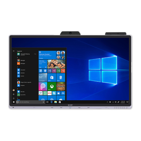
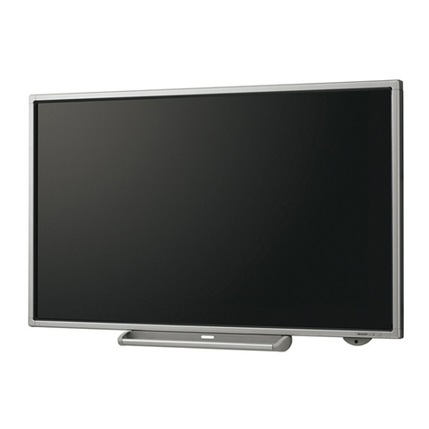
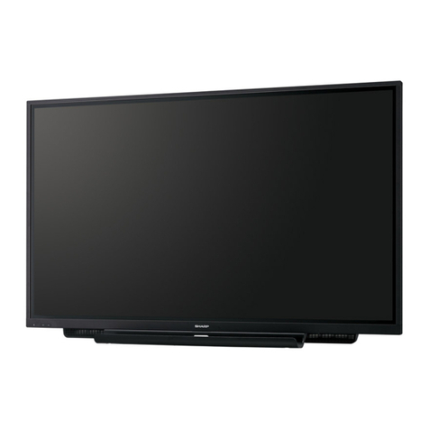
Sharp PN-V701 Instruction sheet

Information Display
Installation Guidelines
<PN-V701>
Sharp Corporation
Business Solutions BU
Visual Solutions Business Unit
October 28th, 2019
Normal Version
<Ver. 1.2>

Copyright ©All rights reserved, SHARP CORPORATION
Confidential 1
Handling of this material/Contents
Contents
1.Overall precautions
1.1. Procedures of installation …P3-5
1.2. Overall precautions …P6
2. Design precautions
2.1. Precautions for temperature and clearance space …P8-11
2.2. Precautions for sunlight …P12
2.3. Countermeasures against dust …P13
2.4. Position of fan …P14
2.5. Reflected glare …P15
2.6. Precautions for dew condensation, water drops, and salt damage …P16
2.7. Vibration/Afterglow/Expansion precautions …P17
2.8. Power supply precautions …P18
2.9. Connecting devices …P19-20
2.10. Precautions for display dimensions …P21
2.11. Precautions for adjacent installation …P22-23
2.12. Inclined orientation …P24
3. Installation precautions
3.1. Major failure modes due to mishandling …P26
3.2. Precautions for carrying …P27
3.3. Prohibitions in storage and transfer in a packaged form …P28
3.4. Installation flow …P29
3.5. Precautions for unpacking …P30
3.6. Precautions in installing and handling …P31-34
3.7. Attachment precautions …P35
3.8. Precautions on stand installation …P36-38
Handling this material
This document is to explain how to design and install large displays for our business partners. Please do
not distribute this document or its contents to other companies, or use it in products of other companies.
Please note that value and expressions on this document are subject to change without notice.
3.9. Precautions for mounting on the wall …P39-40
3.10. Rotate direction for portrait mounting …P41
3.11. Inversion scan function …P42
3.12. Precautions for horizontal installation …P43-45
3.13. Precautions on PC installation …P46
3.14. Maintenance & Checking Items …P47
3.15. Periodical maintenance …P48
4. Color Adjustment
4.1. Installation scheme flow …P50
4.2. Determine a video wall layout by DITwC …P51
4.3. Auto color adjustment by DITwC …P52
4.4. Select uniformity mode …P53
4.5. Fine color adjustment with DITwC …P54
4.6. Calibration with measuring devices …P55
4.7. Color adjusting after calibration …P56
4.8. Software tool …P57-58
4.9. Software function comparison …P59-60
5. Optional tool and installation tool
5.1. A List of Optional/Recommendation tools Peripheral devices …P62
5.2. Dimensions of Peripheral Devices Packaging …P63
5.3. Control Kit PN-ZR02 …P64
5.4. HDBaseT Receiver Board(PN-ZB03H) …P65-68
5.5. Installation tool …P69-74
Copyright ©All rights reserved, SHARP CORPORATION
Confidential 2
1. Overall precautions

Copyright ©All rights reserved, SHARP CORPORATION
Confidential 3
1.1 Procedures of installation
(Please thoroughly observe these recommendations) 1
Check worker’s
clothes and their
belongings.
Wear simple clothes and do NOT
put their mobile phone and/or pen
in their pocket.
We recommend that the following procedures are entrusted to Sharp sales subsidiaries or
dealers/contractors trained by Sharp.
12
The person responsible
for installation directly explains and
shows how to handle the display
securely to the workers before start
installing.
3Prior Explanation
◼How to open the package box of display.
◼How to take the display from the box.
◼How to hold the display/holding positions
◼How to temporarily store the display after taking it from the box.
(We recommend storing the display temporarily on a temporary stand.)
◼How to check and/or store the accessories of display.
4
Install a stand and wall-mounting
brackets.
This model requires close attention to handling due to its thin
bezel. Even dealers or workers familiar with the conventional
models must confirm precautions beforehand Study the
installation guide of this model and stands recommended by BC
Company SHARP as much as possible, and entrust the
installation work to Sharp sales subsidiaries or dealers /contractors
trained by Sharp.
◼Consider the fan
◼Consider the adjacent
positioning
Do not work alone. Make sure to
work with two or more people.
Make enough
working space
before working on.
Check power cable and floor
evenness.

Copyright ©All rights reserved, SHARP CORPORATION
Confidential 4
■Do not put the surface of LCD screen facing down.
■When mounting and moving the
display, be sure to hold it with the
carrying handles. Do not hold any
other parts.
LCD surface
Precautions in Handling
■Don’t touch the
surface of LCD screen. ■Do not grab, impact, or
apply pressure to the top,
bottom, left and right of the
frame.
1.1 Procedures of installation
(Please thoroughly observe these recommendations) 2

Copyright ©All rights reserved, SHARP CORPORATION
Confidential 5
When using remote controller When using key on the rear panel
Ref. You can check the PN-V701’s panel status (color, brightness, damage, or existence or nonexistence of
bright point/black point, light leakage, floating) in accordance with the following procedure.
Note that you can’t check all the features of PN-V701 with the following procedure.
Operation check before installation
Confirm if each display can operate properly prior to the video wall installation. If a failure is
confirmed after installation, the labor and time detaching are required.
Carry out the operation check before installation.
1. Press the [SIZE] button (over 5 sec.) and “F” is
displayed at the upper left of screen.
2. Press the [ ] [ ] [ ] [ ] buttons.
3. The screen display changes in the following sequence,
each time you press the [ ] button.
Black, Dark Blue, Dark Green, Dark Red,
Blue, Green, Red, White, Gray1, Gray2.
4. Turn off the power after checking the display.
1. Press the “MENU” and “INPUT” keys (over 5 sec.)
and “F” is displayed at the upper left of screen.
2 Press the [ ] [ ] [ ] [ ] buttons.
3. The screen display changes in the following sequence,
each time you press the [ ] button.
Black, Dark Blue, Dark Green, Dark Red,
Blue, Green, Red, White, Gray1, Gray2.
4. Turn off the power after checking the display.
1.1.Procedures of installation
(Please thoroughly observe these recommendations) 3
A protective film is attached on the display. Remove it before confirming
operation.After the check, it is recommended to reattach the film
until just before the completion of installation to protect the display. Corner protective
materials Tape
Protective
film

Copyright ©All rights reserved, SHARP CORPORATION
Confidential 6
1.2.Overall precautions
Precautions for Usage, Installation
- Do not use the display under following conditions ;
1) beyond its capability, feature/function, accuracy/precision,
2) that may cause injury or life-threatening situation under product failures,
3) and that may lead to significant financial losses.
We will not take any responsibility if the product was used under above conditions.
<Example>
Control of all types of safety related usage of transportation equipment (air plane, train, car, etc.), aerospace
equipment, communication equipment, nuclear control equipment, medical equipment, disaster-prevention/security
equipment, all types of safety equipment, etc.
-We will not take any responsibility for any failure, damage, loss, etc. which arise from particular installation
(high-ceiling mounting etc.) and/or installation by other companies than Sharp. Prior to the installation, examine the
potential problems caused by the installation location and installation method, and operate within the appropriate
environment.
-In case of product failures, regardless of warranty period, removal and installation are carried out at customer’s
expense. It may take a certain period to repair products, so we recommend preparing an additional display.
-Installation environment of the display differs from individual cases. Carry out appropriate installation
according to this guidelines. If you have any trouble judging whether the displays can be installed or have any
comments/questions about the contents of this guidelines, please ask SHARP sales subsidiaries.

Copyright ©All rights reserved, SHARP CORPORATION
Confidential 7
2. Design precautions

Copyright ©All rights reserved, SHARP CORPORATION
Confidential 8
Temperature in the display will heat up if the air clearance space is not enough.
-When the temperature is too high, electronic components and the fan’s life time will be shortened or breakdown.
- When the heat gets trapped in the display, the temperature will rise, the brightness of back-light will be
lowered, and the LCD screen will be darkened. When the temperature inside gets too high, the power will be turned off
and the display will go into the standby mode.
Temperature
Heat on LCD surface
When the temperature on the surface of the LCD screen is too high, it will break down or uniformity issue will occur.
2.1.Precautions for temperature and clearance space 1

Copyright ©All rights reserved, SHARP CORPORATION
Confidential 9
Space requirement (Top/Bottom/Left/Right)
Top 20 cm
Bottom 10 cm
Left/Right 10 cm
Behind Clearance space and surrounding
temperature should be controlled.
(refer to the next page)
Surface Consult us.
Temperature control and clearance space
Main unit, PN-ZR02(Remote-control signal receiving kit)
- Usable temperature range
0 ℃to 40 ℃*
* Maximum temperature when video wall system is operating
- Clearance space
1. Space should be secured between front/back/
above/below/right/left of the display
2. The operating temperature must be carefully
controlled depending on the configurations of video
wall and clearance space at the back.
- Temperature of LCD surface
Under 60 ℃
Follow the requirements above when installing video wall
display.
Refer to the countermeasures and follow the installation
conditions when installing video wall. (Follow the installation
conditions for peripheral devices as well.)
Secure the space at the top/bottom/left/right/front/rear of
display regardless of wall-hanging or stand type installation.
A point for measuring temperature
Measure the temperature at 1 meter away from the
center of LCD surface.
Surface of LCD video wall
1m
view
Note: Inquire us when you install displays in an environment
where surroundings are not opened such as in-wall installation.
.
2.1.Precautions for temperature and clearance space 2

Copyright ©All rights reserved, SHARP CORPORATION
Confidential 10
Space requirements (Behind)
Relation between the rear clearance space and operating temperature
Replacement is recommended every 5 years when fulfilling the above requirements.
Note: It is just a guide and it shall not warrant the product life. The actual product life may vary depending on the operating environment such as
hours of use, ambient temperature change, the amount of dust, and regular maintenance. Even within the warranty period, the replacement of
fan caused by failure is charged. The warranty does not include pre-mature fan failure.
This model has a fan. In landscape installation, the fan is rotated when the temperature is above 30℃. It isn’t rotated
in portrait installation.
User menu does not have settings to turn ON/OFF the fan or to control the rotation speed.
Note: This clearance space is for when LCD surface (front) is in open space without being covered.
2 x 2 landscape video wall (Unit: degree Celsius )
Clearance space at the back side
3.5cm or more
10.0cm or more
20.0cm or more
30.0cm or more
40.0cm or more
50.0cm or more
70.0cm or more
37.5
℃
or less
38.0
℃
or less
38.5
℃
or less
39.0
℃
or less
39.0
℃
or less
39.5
℃
or less
40.0
℃
or less
1 x 3 portrait video wall (Unit: degree Celsius )
Clearance space at the back side
3.5cm or more
10.0cm or more
20.0cm or more
30.0cm or more
40.0cm or more
50.0cm or more
70.0cm or more
37.5
℃
or less
38.0
℃
or less
38.0
℃
or less
38.0
℃
or less
38.0
℃
or less
38.5
℃
or less
39.0
℃
or less
5 x 5 landscape video wall (Unit: degree Celsius )
Clearance space at the back side
3.5cm or more
10.0cm or more
20.0cm or more
30.0cm or more
40.0cm or more
50.0cm or more
70.0cm or more
33.5
℃
or less
34.0
℃
or less
34.5
℃
or less
35.0
℃
or less
35.0
℃
or less
35.5
℃
or less
36.0
℃
or less
3 x 3 landscape video wall (Unit: degree Celsius )
Clearance space at the back side
3.5cm or more
10.0cm or more
20.0cm or more
30.0cm or more
40.0cm or more
50.0cm or more
70.0cm or more
35.5
℃
or less
36.0
℃
or less
36.5
℃
or less
37.0
℃
or less
37.0
℃
or less
37.5
℃
or less
38.0
℃
or less
2.1.Precautions for temperature and clearance space 3

Copyright ©All rights reserved, SHARP CORPORATION
Confidential 11
- If it is difficult to secure spaces or if the surrounding temperature goes under 0 ℃or beyond 40 ℃,
take some measures, such as installing the air-conditioner to control the surrounding temperature
to be around 0 ℃to 40 ℃.
- Add a cooling fan
- Widen the ventilation space
- Using an air-conditioner or a fan
- Lower the brightness of display
*The effectiveness of each countermeasure differs
depending on the installation environment. Choose
the best measure for respective environment.
Countermeasures for the lack of clearance space
Fan installation
Heat prevention unit
(Apiste co.)
2.1.Precautions for temperature and clearance space 4

Copyright ©All rights reserved, SHARP CORPORATION
Confidential 12
Sunlight Countermeasures
Setting a sun-shade
Utilizing the shade of the building
Installing the display back to the
place without direct sunlight
This display is designed for indoor use only. Avoid the direct sun, wind, or rain. These conditions may cause failures or deterioration.
2.2.Precautions for sunlight
Do not expose to the direct sun.
Install the product in shaded areas to keep it away from the
direct sun especially when using it outdoor/semi-outdoor.
- Set a sun-shade above the display
- Utilize the shade of the building
- Install the display in a place without direct sunlight
- Change the direction of the display to avoid sunlight
- Utilize trees or some objects blocking out the direct sunlight
(Be careful about strong wind, like hurricanes.)
Effect
If being used under direct sunlight;
- The LCD screen would look much darker than usual.
- LCD would be deteriorated due to ultraviolet rays.
- The display would be damaged.
An uniformity issue would occur.
Cabinet would be deformed due to the heat.
(The temperature at a part of the display in a direct sunlight could be high
even the environmental temperature is fairly low.)
e.g. LCD screen darkeninge.g. LCD screen darkening

Copyright ©All rights reserved, SHARP CORPORATION
Confidential 13
Prevent any dust exposure construction work near
the wall mounted display.
2.3.Countermeasures against dust
Dust
This product is designed for indoor use only.
When using it outdoor, or at dusty places, such as railway
station, take some countermeasures against dust.
Refer to the countermeasure below before installation.
Damages
Dust may get under the LCD panel from the gaps and it may
spoil the image (as below), and may cause failures.
Dust coming from under the LCD
panel damaged the image quality.
Countermeasure
Create a completely sealed casing.
It can shut off dust and enables installation in dusty places, outdoor,
and a place where salt damage might be occurred.
The temperature in the sealed casing would be higher.
Countermeasures against the heat are required, such as installing a
heat exchanger or an air conditioner.
*To maintain the quality of the casing, regular maintenance is needed.
Precautions for using anti-dust display
When using a display casing, mount an anti-dust air filter.
Precautions for Anti-dust air filter
- Double filter makes its life longer by replacing the finer screen pre-
filter.
- A filter increases the air resistance.
It may raise the internal temperature of the casing.
Reduce the air resistance by using larger filter.
- The following points should be taken care of in designing the casing
with intake/exhaust fan.
Intake fan:
The advantage: The casing inside is kept under positive pressure so
the dust is not drawn into.
The disadvantage: It is difficult to pull much air into the casing due to
the air resistance (when using in dusty place).
Exhaust fan:
The advantage: It is easy to control the temperature in the cabinet.
(when using in less dusty place and in severe temperature
environment).
The disadvantage: The casing inside is kept under negative pressure,
so the dust is drawn into through the vents and cracks.
*Filters must be cleaned frequently to keep good performance,
Intake fan Exhaust fan
Pressure within cabinet will
be high, preventing dust from
entering through small gaps.
Pressure within cabinet will
be low, making dust drawn in
through small gaps.

Copyright ©All rights reserved, SHARP CORPORATION
Confidential 14
DO NOT cover the fan cover area for replacing the fan.
2.4.Position of fan
Fan-cover is
attached firmly
with screws.
(303.21)
Cover removal
Do NOT cover this area
for replacing of cooling
fan.
(172)
(172) (54.45)

Copyright ©All rights reserved, SHARP CORPORATION
Confidential 15
2.5.Reflected glare
Reflected Glare
◆Reflected glare may occur and may degrade visibility due to a guard panel.
◆The following two anti-glare screen protectors are effective to prevent the reflected glare.
-AR coating: reduces reflection and eliminates stray light.
-AG coating: reduces reflection with scattered reflected light.
◆The price of AG coating is lower than that of AR coating, however, images easily defocus and the view
angle is narrow in AG coating. Select the best screen protector for your purposes.
◆Generally, when decreasing glare, image quality comes down. Select the suitable protection panel in each
installing site.
◆The closer a distance from the protection panel to the LCD panel is, the more clear image you can get, but
temperature on the LCD surface rises if it’s too close.
◆Secure space (of 3cm at least) between protective panel (or glass) and the LCD surface to let the
air flow through between them so that temperature of the LCD surface won’t rise to 60℃or more.
When you use air flow fan, sufficient examination is needed before installation.
AG AR
LCD surface
temperature
must be
below 60℃.
Secure space
Air
Flow
Light Light
Guard Panel
A space of as least 3cm
is required for natural
air flow.

Copyright ©All rights reserved, SHARP CORPORATION
Confidential 16
2.6.Precautions for dew condensation, water drops,
and salt damage
Dew condensation, water drops, and salt damage
-This display is designed for indoor use only. Avoid the direct sunlight, wind, or rain. These may cause failures and/or deterioration.
- Range of humidity condition for IDP: From 20% to 80% (no condensation)
- Dew condensation and/or liquid drops will cause the breakdown of the circuit and/or LCD panel.
Install LCD away from condensation and liquid drops.
- The environment which has high possibility of condensation:
The place where temperature is generally low but has frequent warm air flow.
(e.g. When the radiator is turn on in a cold winter morning, condensation occurs in the place in front of the vents of radiators.)
Near the sea or lakes, where there is high humidity.
- The environment which has high possibility of liquid drops:
“Semi-outdoor” where strong winded-rain (typhoon) could potentially reach the display.
Below the pipes in the ceiling, when the pipes have leaking problems, drops of water may enter the display through the vents.
(When you install in these places, take some countermeasures such as covering the display with a box with a consideration of a
direction of the vents.)
- Precaution for wind (e.g. typhoon):
DO NOT set the display in the place where may be affected by wind.
- Precaution for salt water/salty breezes:
When installing close to sea, consult us for potential damage from salt water.
- Precaution for sulfur:
DO NOT set the display in the place where may be affected by sulfur(e.g. hot spring or volcano).
- Precaution for organic gas or flammable gas:
DO NOT set the display in the place where may be affected by organic gas or flammable gas.

Copyright ©All rights reserved, SHARP CORPORATION
Confidential 17
2.7.Vibration/Afterglow/Expansion precautions
This display is not designed to set in any places with strong
vibrations, such as in motor vehicles.
If the display will be used in the place with possibility of even
small vibration, such as at railway station’s platform, take
some measures such as using a shock absorber .
Vibration
・When a still image is being displayed for a long period,
afterglow might occur.
It can be removed by playing videos or turning off the
display. The longer period of time a still image is being
displayed, the harder it is to remove afterglow. Change the
image occasionally.
Afterglow
When using acrylic or polycarbonate protection panel, be
aware of expansion due to heat or moisture absorption.
Acrylic protection panel can expand about 0.4%
(approx. 6.2 mm : 70”)
Install the protection panel with a space so that it won’t be
distorted due to expansion.
Expansion
・The followings are expected to prevent afterglow.
-Display video as long as possible. (e.g. display 10 seconds’
video after 5 minutes’ still image)
- Prevent increase of the contrast difference between
background and content. Change the color occasionally.
- Utilize functions to prevent afterglow as below;
[Screen Motion Function]
Prevent afterglow by moving the whole screen up and down,
and right and left.
Refer to the operation manual for the detailed operation method.
[Backlight Off Function]
Turn off the backlight and display the preventing afterglow
patterns in a power supply standby mode or signal standby
mode.
Ask SHARP Sales Department about the detailed operation method.

Copyright ©All rights reserved, SHARP CORPORATION
Confidential 18
Power Supply and Voltage
Circuit breaker
box
Display
Display
Display
Display
Circuit A Circuit B
2.8.Power supply precautions
-PN-V701 is designed to be used under commercial 100V-240V power
supply, but shortage of power supply may occur in wall video installation.
- Arrange plural circuit and level power consumption in each circuit.
- Avoid over power consumption such as by delaying the wake-up time using
power-on delay function.
Movable Blade Plug Normal Blade Type
No bushed Bushed
Power Strip
-Confirm the rated current value of the power strip. The total amount of current consumption of
all the connected devices shouldn’t exceed the rated current value.
- Avoid using a movable blade plug which may be damaged if
excess force is applied to. It may also cause abnormal heat
generation even under the rated current value. We recommend a
normal blade type.
- The inner core wire may be damaged and cause abnormal heat
generation if the code is pulled with excess force. We recommend
the code fixed with bushing.

Copyright ©All rights reserved, SHARP CORPORATION
Confidential 19
2.9.Connecting devices 1
You can control display functions by PC by connecting RS-232C or LAN. (e.g. power on/off function)
We recommend connecting RS-232C or LAN to displays before installing them in higher place or other
places where it is hard to connect cables after installation. They may need in future display maintenances.
-In analog connection, image quality might be influenced by a video board or cable.All displays requires
adjustment when installed. We recommend digital connection(e.g. HDMI, DVI, or DisplayPort connection)
for high quality images.
-When you use light conversion cable to extend the transmission distance, EDID may not be read
accurately. Not reading EDID accurately, displays cannot display correctly. Check the image quality
beforehand when using these devices.
Cable
When you use media devices (e.g. personal computer, DVD player) or peripheral equipment (e.g.
distributor, video switching unit), check the connection operation of the devices boforehand.
Media Devices and Peripheral Equipment
RS-232C/LAN
-When connecting DisplayPort terminal of PC that is not DP++ standard with HDMI or DVI terminal of
display, use the active type of the connecting cable (DisplayPort-HDMI(or DVI) conversion cable) and
check how it works beforehand.
Other manuals for PN-V701
2
Table of contents
Other Sharp Monitor manuals

Sharp
Sharp PN-M401 User guide

Sharp
Sharp PN-L705H User guide

Sharp
Sharp PN-L401C User guide

Sharp
Sharp LC-121M2E User manual

Sharp
Sharp PN-HM851 Quick start guide

Sharp
Sharp PN-B501 Quick start guide

Sharp
Sharp LL-T15G3 User manual

Sharp
Sharp PN-455 User manual

Sharp
Sharp PN-H801 User guide

Sharp
Sharp PN-S655 User manual

Sharp
Sharp PN-455RU User manual

Sharp
Sharp 5030i User manual

Sharp
Sharp PN-HW751 User manual

Sharp
Sharp LV-70X500E User manual

Sharp
Sharp PN-R703 User manual

Sharp
Sharp TL-M5200 User manual

Sharp
Sharp PN-70SC3 User guide

Sharp
Sharp PN-L805H User manual

Sharp
Sharp PN-HE751 User manual

Sharp
Sharp PN-K321 User manual