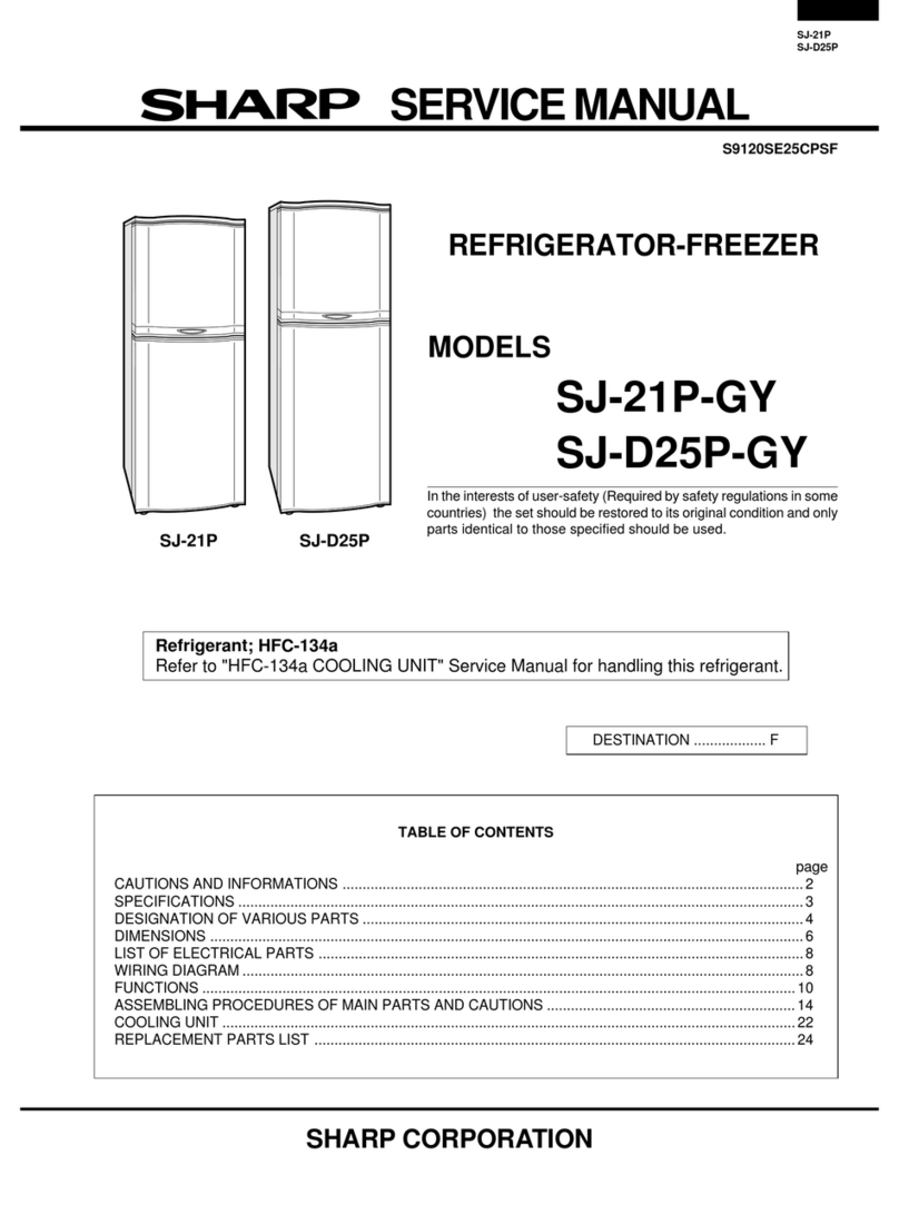
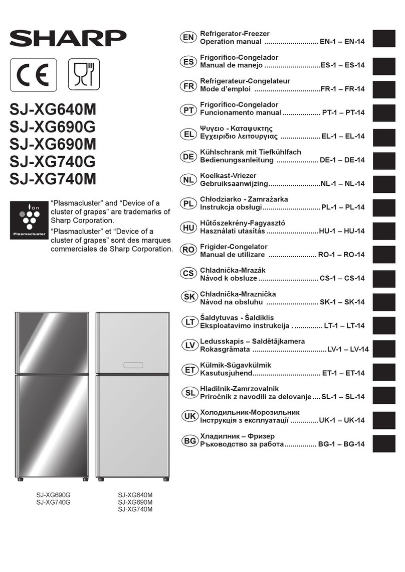
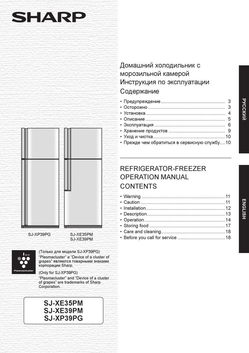
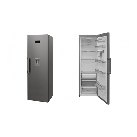
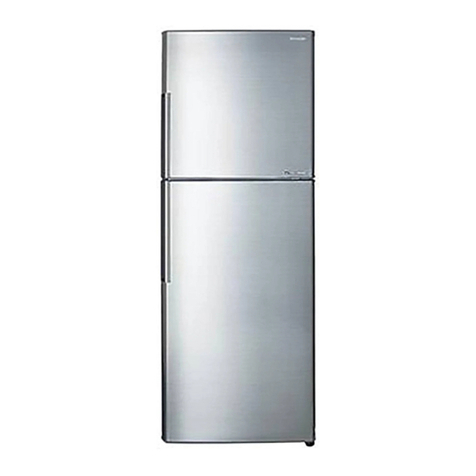
Sharp SJ-FS810V-WH User manual

SERVICE MANUAL
This document has been published to be used for
after sales service only.
The contents are subject to change without notice.
DESTINATION J
CONTENTS
Refer to "REFRIGERATING-CYCLE REPAIR MANUAL" for handling this refrigerant.
Refrigerant; R600a
Refrigerator-freezer
MODEL
SJ-FS810V-
WH
No.SX528SJ79AHTJT
DEFINITION OF SERIAL NUMBER FOR VESTEL
[1]INSTALATION …………………………………… 2
[2] SPECIFICATIONS ……………………………… 3
[3] FICHE …………………………………………… 5
4] DESIGNATION OF VARIOUS PARTS ……… 6
1. EXTERNAL DESCRIPTION ……………… 6
2. CONSTRUCTIONS ………………………… 7
[5] DIMENSIONS
1. OUTER DIMENSIONS AND CLEARANCE 8
2. INNER DIMENSIONS ……………………… 8
[6] LIST OF ELECTRICAL PARTS ……………… 9
[7] WIRING DIAGRAM
1. WIRING DIAGRAM ………………………… 10
2. ELECTRIC ACCESSORIES LAYOUT … 11
3.
PRECAUTIONS FOR USING LEAD-FREE SOLDER
12
[8] FAILURE DIAGNOSIS
1. OUTLINE OF CONTROL …………………… 13
2.
WHEN THE DEFROSTING FAILURE IS DOUBTFUL
13
3.
RE-SETTING OF MICROCOMPUTER AT POWER FAILURE
14
4.
DIAGNOSIS METHOD OF FAILURE AROUND PWB
14
5.
CONVERSION TABLE BETWEEN TEMPERATURE AND ………
RESISTANCE VALUE
……………………………… 15
[9] CIRCUIT DIAGRAM OF MAIN PWB………… 17
[10] SELF-DIAGNOSIS MODE…………………… 19
[11] MODE FOR DISPLAY………………………… 26
[12]
DISASSEMBLING/ASSEMBLING PROCEDURES
1. REFRIGERATOR COMPARTMENT …… 27
2. FREEZER COMPARTMENT ……………… 35
3.
WHEN LEFT AND RIGHT DOORS
ARE NOT ON THE SAME LEVEL
………………46
[13] COOLING UNIT ……………………………… 47
1. COOLING UNIT ……………………………… 47
2. LOCATION ……………………………………48
Parts Guide

SJFS810VWH
2
1. Name label
Initial letter of serial number : J
The serial number on the “Name label” and “Feature label”
2. Feature label
J : Vestel Electronics
・DEFINITION of serial number for VESTEL
SJ-FS810V-WH
J 160100001
SJ-FJ810V-BKSJ-FJ810V-BK
SERIAL NO.
WIRING DIAGRAM
SJ
-F
S8
1
0
V-
S
L
J
1
6 0 1 0 000 1
S
ERIAL N
O.
M
O
DEL
:
[1]INSTALATION
Free standing type
•To ensure adequate ventilation for this refrigerator, install with 6 cm space at the rear and both sides, with a
minimum space of 9 cm above the refrigerator.
•This refrigerator shall be used under the ordinary place condition between +5 ºC and +43 ºC of ambient
temperature, and also not be left under -10 ºC for long days.
•To be used this refrigerator within the range of the rated voltage±6%.
6cm
6cm
9cm

SJFS810VWH
3
[2] SPECIFICATIONS
Items SJ-FS810V
Type 4 Door
Outer dimensions Height 1830 mm ( 72.0 ")
Width 892 mm ( 35.1 ")
Depth 766 mm ( 30.2 ")
Rated storage volume Total 600liter (21.2 cu.ft)
Freezer 207liter (7.3 cu.ft)
Refrigerator 393liter(13.9 cu.ft)
Rated gross volume Total 678liter(23.9 cu.ft)
Defrosting System Heater system
Start Automatic
Finish Automatic
Door material Glass
Plasmacluster unit 1
Temperature control Automatic (Adjustable)
No-frost freezer Yes
Interior lamp (LED) 48
Caster 4
Evaporating pan 1 (unremovable)
Refrigerator Compartment R-shelf ass'y 2
V-shelf ass'y 1
Fruit case ass'y 1
Fresh case ass'y 1
V-case ass'y 1
Door pocket ass'y 3
Bottle pocket L ass'y 1
Bottle pocket R ass'y 1
Bttl pocket partition 1
U-pok door 1
Utility pocket ass'y 1
Egg pocket ass'y 1
Egg tray 1
Water tank 1
Freezer Compartment Auto ice maker 1
Ice storage box 1
F-case S ass'y 3
L-case S ass'y 2
Control panel Plasmacluster Yes
Energy saving Yes
Express Freezing Yes
Vacation mode Yes
Door alarm Yes
Temp.control Yes
Child lock Yes
Ice making Yes
Large ice making Yes
Clear ice making Yes
Ice tray cleaning Yes
Aluminium panel Yes
Deodorizing unit (Honeycomb type) Yes
RATING
Items SJ-FS810V
Rated voltage (V~) 220-240
Rated frequency (Hz) 50
Climate class SN-T
Rated current (A) 1.3-1.4
Rated input of heating systems (W) 191-223
Defrosting input (W) 173-206
Refrigerant (Charging quantity) [Flammable] R600a(83g)
Insulation blowing gas [Flammable] Cyclo pentane (HC)
Net Weight (kg) 118

SJFS810VWH
4
PLUG TYPE
Plug cord 2pin+Earth
Plug type CS
Destination mark E
COLOR
Items -WH
Outside color White
Inside color White
AUTOMATIC ICE MAKER
•Water supply system …… Water is sent from the water tank to the ice tray.
•Water tank capacity …… Approx. 1.8L
•Ice-making capability
Ice size Normal Large
One day Approx. 1.2kg Approx. 1.5kg
One time
(eight pieces) Approx. 100g Approx. 230g
•Time required for one ice making
Ice size Normal Large
Normal ice Approx. 2 hours Approx. 3 and
a half hours
Clear ice Approx. 6 hours Approx. 8 hours
•Others …… Mesh filter
Shovel (for ice extraction )
A check of operation can be performed in cleaning mode.
•Heat-resistant temperature of a water tank …… Approx. 60 °C
•Ice cube volume (Maximum)
Ice size Normal Large
Volume Approx. 232 pieces Approx. 112 pieces
Receptacle

SJFS810VWH
5
[3] FICHE
ANNEX Ⅲ
(EU) Regulation No.1060/2010
ATrade mark
BModel name SJ-FS810V
CCategory 7
DEnergy class A+
EEU Ecolabel award —
FAnnual energy consumption *1 [KWh/
year] 487
GStorage volume of all compartments that
do not merit a star rating [ L ] 393
HStorage volume of all frozen-foodstorage
compartments that merit a star rating [ L ] 207
IThe design temperature of “other
compartment” warmer than +14°C —
JFrost free YES
KTemperature rise time [ h ] 17
LFreezing capacity [Kg/24h] 9.5
MClimate class SN-T
NAirborne acoustic noise emission [dB(A)] 37
OBuilt-in appliance No (Free-standing type)
*1Energy consumption “XYZ” kWh per year,based on standard test results for 24 hours.
Actual energy consumption will depend on how the appliance is used and where it is located.

SJFS810VWH
6
[4] DESIGNATION OF VARIOUS PARTS
1. EXTERNAL DESCRIPTION
The names in parenthesis “[ ]” are the denominations used in the PARTS GUIDE.
1. Door pockets [Door pocket ass’y]
2. Refrigerator shelves [R-shelf ass’y]
3. Shelf [V-shelf ass’y]
4. Bottle pocket [Btl-pok L ass’y]
5. Vegetable crisper [V-case ass’y]
6. Freezer case s [F-case S ass’y]
7. Freezer case l [F-case L ass’y]
8. Casters
9. Adjustable feet [Adjustable leg ass’y]
10. Foot cover [Base cover]
11.Aluminum panel [AL panel]
12.Light [Top led PWB ass’y]
13.Light [LR led PWB ass’y]
14.Utility pocket cover [U-pok door]
15.Utility pocket [Utility pok ass’y]
16.Egg pocket [Egg pok ass’y]
17.Egg holder [Egg tray]
18.Fruit case [Fruit case ass’y]
19.Bottle pocket [Btl-pok R ass’y]
20.Water tank
25
26
18
19
5
23 23
23 23
24
22
7 7
6
6
8 8
99
10
1113 13
14
15
1
17
16
20
21
12 12
Shovel
Noise-prevention
sheet
[Noise-proof sheet]
[Icescoop]
21. Fresh case [Fresh case ass’y]
22. Ice storage box [Ice storage box ass’y]
23. Magnetic door seals [Door packing]
24. Eco sign [Multicolor PWB ass’y]
25. Touch control panel [OP PWB ass’y]
26. Handle indicator
[Handle PWB upper / lower ass’y]

SJFS810VWH
7
2. CONSTRUCTIONS
Cold air flow
ELE90BH
PWB-s ass'y
Ionizer-K
R-thermistor
R fan motor
Damper ass'y
Compressor
Protector
Gear pump
Evaporator
Fuse ass'y
F/DF-thermistor
F-fan motor
Defrost heater
Door sw PWB
OP PWB ass'y
Handle PWB
upper ass'y
Handle PWB
lower ass'y
Lr led PWB ass'y
Top led PWB ass'y
Lr led PWB ass'y
Multicolor
PWB ass'y
Discharge pipe
Foot cover
Adjustable feet
Caster
Thermistor
Ice cube heater
Tank heater
PTC relay
Running capacitor

SJFS810VWH
8
[5] DIMENSIONS
1. OUTER DIMENSIONS AND CLEARANCE
Refrigerator
Freezer
with badge thickness
more than 60
more
than
90
766
680
892
1006
11
753.5
56.5
897
1830
1120
887
1334
235
212
313285
1500
118
118
132
132
more than
60
more than
60
2. INNER DIMENSIONS
The dimensions between shelves can be changed by setting the shelves on the other rails.
152
137.5
152
137.5
152
137.5
391
788 12
413.7
420
413
254
316.5
12
88
7
5
4
207
345
400
400
193
167
152
137.5
137.5
152
152
137.5
210.5
225
420
413
418
359
324
324
359
324
359
359
324
324
357.6
324
359
324
357.6
142.5
317
317
317 317
317
235
112
217
354.5
100.5
770
770
770
111.5142.5
260.5
260.5 142.5 142.5
313
125.5 96.2
340

SJFS810VWH
9
[6] LIST OF ELECTRICAL PARTS
ITEMS PARTS CODE TYPE NAME RATING SPECIFICATIONS
R thermistor RH-HXA158CBZZ -DC5V R0=6.4kΩ,B(0)=3811
F /DEF thermistor RH-HXA108CBZZ -DC5V (F)R0=6.4kΩ,B(0)=3811
(DEF)R0=15kΩ,B(0)=3811
Damper ass'y DTHM-A031CBKZ -DC12V -
R fan motor RMOTRA095CBZZ D08A-12PM05(K) DC12V -
F fan motor RMOTRA096CBZZ FBA12J15V XD DC15V -
Fuse ass'y FFS-TA087CBK Z SF70E 250V 10A Working temp. : 73 ℃
Defrost heater FHETBA193CBZZ -220V-240V286Ω 185W at 230V
LR LED PWB ass'y FPWB-B270CBKZ -DC25mA White LED Lamp 18pcs × 2lines
TOP LED PWB ass'y FPWB-B268CBKZ -DC50mA White LED Lamp 6pcs × 2lines
Multicolor PWB ass'y FPWB-A940CBKZ -Blue LED:DC15mA
Orange LED:DC20mA
Blue LED:1pcs
Orange LED:1pcs
Door switch PWB FPWB-A917CBKZ -DC5V -
Ice maker ass'y DVM A -A127CB K Z -DC12V
Ice thermistor RH-HXA157CBZZ -DC5V R0=6.0kΩ,B(0)=3811
Gear pump FGER-A014CBZZ -DC12V -
Ice cube heater FHETBA389CBZZ -DC24V12W(48Ω) -
Tank heater FHETBA390CBZZ -DC24V1.0W(576Ω) -
Water pipe heater RHETBA388CBZZ -DC24V2.8W(206Ω) -
Rd-heater RHETBA391CBZZ -230V6.32W(8365Ω) -
Plasmacluster unit CKITTA159AKKZ -DC15V 4.55kV p-p (Second wave)
Compressor FCMPLA441CBKZ NX1120Y 220-240V / 50Hz Cooling capacity : 232W
Maincoil:13.9Ω
Aux.coil:17.9Ω
(at 25 ℃)
Starting relay (PTC relay) RSTT-A245CBZZ PTH7M150MD2 -15Ω(at25℃)
Overload Relay (Protector) RHOG-A302CBZZ 4TM222NFBYY-53 -Open/Close : 120/61℃
Running capacitor RC-EZA250CBZZ - 230V (220-240V) 400V4μF
Main PWB ass'y FPWB-B090CBKZ - 220-240V 50/60Hz -
Operation panel PWB ass'y FPWB-A909CBKZ -DC24V -
Handle PWB upper ass'y FPWB-A905CBKZ -DC10V RGB LED Lamp : 1pcs
Handle PWB lower ass'y FPWB-A907CBKZ -DC10V RGB LED Lamp : 1pcs
:Unexchengeable parts or Independently unexchangeable parts.
Common
Main coil Aux. coil
SJFS810VWH
10
[7] WIRING DIAGRAM
1. WIRING DIAGRAM
Besuretoreplacetheelectricalpartswithspeciedonesformaintainingthesafetyandperformanceoftheset.
BK:BLACK
BR:BROWN
R : RED
O : ORANGE
Y : YELLOW
GR : GREEN
BL : BLUE
V : VIOLET
GY : GRAY
W : WHITE
P : PINK
SB:SKY-BLUE
G/Y : GREEN/YELLOW STRIPE

SJFS810VWH
11
2. ELECTRIC ACCESSORIES LAYOUT

SJFS810VWH
12
3. PRECAUTIONS FOR USING LEAD-FREE SOLDER
1) Employing lead-free solder
The PWB of this model employs lead-free solder. This is indicated by the "LF" symbol printed on the PWB and in the
servicemanual.Thesufxletterindicatesthealloytypeofthesolder.
Example:
Indicates lead-free solder of tin, silver and copper
2) Using lead-free wire solder
When repairing a PWB with the "LF" symbol, only lead-free solder should be used. (Using normal tin/lead alloy
solder may result in cold soldered joints and damage to printed patterns.)
As the melting point of lead-free solder is approximately 40°C higher than tin/lead alloy solder, it is recommend that a
dedicated bit is used, and that the iron temperature is adjusted accordingly.
3) Soldering
Asthemeltingpointoflead-freesolder(Sn-Ag-Cu)ishigherandhaspoorerwettability,(ow),topreventdamage
to the land of the PWB, extreme care should be taken not to leave the bit in contact with the PWB for an extended
periodoftime.Removethebitassoonasagoodowisachieved.Thehighcontentoftininleadfreesolderwill
cause premature corrosion of the bit. To reduce wear on the bit, reduce the temperature or turn off the iron when it is
not required.
Leaving different types of solder on the bit will cause contamination of the different alloys, which will alter their
characteristics,makinggoodsolderingmoredifcult.Itwillbenecessarytocleanandreplacebitsmoreoftenwhen
using lead-free solder. To reduce bit wear, care should be taken to clean the bit thoroughly after each use.

SJFS810VWH
13
[8] FAILURE DIAGNOSIS
1. OUTLINE OF CONTROL
1) ON/OFF Control of Compressor
•ON/OFF of the compressor will be controlled depend on the temperature detected by the R-thermistor and
F-thermistor. (Normal cooling control)
•In case the surrounding temperature is high at the power supply input, the compressor will be ON at once and the
normal cooling control will start after several hours.
•When the Express freezing is requested by user during the operation, the compressor will be ON and cooling
operation will be started regardless of the detected temperature by the thermistors. However, if requested during the
defrosting operation, the request will be executed after the completion of defrosting and ON of the compressor might
be delayed.
•During 6 minutes after the compressor stops, it will not start regardless of the detected temperature by R-thermistor
and F-thermistor.
2) Defrosting
Microcomputer calculates the appropriate timing of defrosting and defrosting is made automatically. Therefore
no manual operation by user is required. The cycle of defrosting varies depend on the usage condition of the
refrigerator. (Maximum time about 50 hours, minimum time 8 hours)
3) Thermistor
Thermistors are installed in 5 places; in the refrigerator and freezer compartment, and close to the Operation PWB
and Evaporator and the bottom of the ice tray. (R-thermistor, Fthermistor, Outside temp-thermistor, Def-thermistor,
Ice-thermistor)
R-thermistor and F-thermistor detects the temperature in the refrigerator and freezer compartment respectively and
controls ON/OFF of compressor.
Def-thermistor detects the temperature around the evaporator and shows the progress of defrosting.
Outside temp-thermistor detects the surrounding temperature of refrigerator. The microcomputer decide the
operation mode using the outside temperature.
Ice-thermistor detects the end of ice making, and water existence in Auto Ice maker.
4) Auto Ice Maker
•Automatic Ice maker operation
Releasing (Ice tray rotates)
Water supply (Gear pump moves) Ice -thermistor detects water existence Ice -thermistor detects the end of ice making
•Clear ice
An ice cube heater is heated and ice is made slowly.
•Water pipe heater
Freezeproongofawaterpipe.
•Tank heater
Freezeproongofawatertank.
5) R room lamp
•R room lamp goes out, 60minutes after opening a refrigerating room doors. (for power supply circuit protection)
2. WHEN THE DEFROSTING FAILURE IS DOUBTFUL
Execute the Self-Diagnosis Mode. (Refer to the Chapter “SELF-DIAGNOSIS MODE”)
•In case the diagnosis result is “ E.03” (Def-thermistor system defect), follow up the flowchart of E.03. (In case of
any abnormity in the Def-thermistor, defrosting will not be made for safety reasons.)
•In case the diagnosis result is “ E.07” (Defrost defect), follow up the flowchart of E.07.
(This diagnosis result will be displayed when defrosting is made for 120 minutes, the maximum time length. In
this case, the defect of PWB itself or also the breakage of heater or heater circuit (melt down of current fuse and
temperature fuse) are considerable.)

SJFS810VWH
14
3. RE-SETTING OF MICROCOMPUTER AT POWER FAILURE
•At the power failure for over about 1 second, the control of the microcomputer will be reset.
•Microcomputer might continue to operate for approximately 10 seconds maximum at power failure depending on
the load at the operation. Approximately 30 seconds is necessary for the definite power OFF condition.
•When the power is re-supplied, the normal cooling will be resumed.
•The temperature and operation mode set by user will be maintained even if a power failure occurred. (However
express freezing, and ice tray cleaning will not be maintained.)
•When the mode for display is released after to be made, each mode and setting are resumed to the initial condition.
4. DIAGNOSIS METHOD OF FAILURE AROUND PWB
First of all, check by using the self-diagnosis.
In case that the power supply doesn't enter, check by the following procedure.
1.Disconnect power supply and check the following point.
•Is there any failure portion in inserting connectors?
2.Detach the PWB and check the appearance.
•Is there any burning or abnormal damage?
3.Check the conditions of the fuse and the varistor. (Fuse and varistor are located at the position in the figure.)
•Under the condition of power supply plug connected;
In case of no cooling and no indoor lamp lighting, there might be a possibility of fuse (F1 or F2) melt down.
When the fuse F1 or F2 is melt down, PWB does not operate at all.
WhenthefuseF3ismeltdown,defrostingheaterandrefrigeratordoorheaterarenotelectried.(Defrostingerror
will be diagnosed as “Defrosting failure” by the self diagnosis.) In this case, the cooling performance may
deteriorate or dew generation may occur on the door, because the defrosting is not done.
•Melting in the fuse cannot be checked visually (as the safer one than transparent glass tube is used). Be sure to
detach the connector “CN1” before measuring the resistance between the both ends of the fuse by the tester.
•Next, measure the resistance value between the both leads of the varistor.
Fuse1
Fuse2
Fuse3
Varistor3 Varistor1

SJFS810VWH
15
Varistor
Normal(overapprox.1.5MΩ) Damage
Fuse
Melting
Flow of excessive current is considerable for
some reasons.
Check for any portion to cause short circuits
especially on the primary circuit.
There is a possibility of excessive voltage applied from outside
with the factor such as thunder etc.
When repeated with a factor other than thunder, there might be
the apparatus near by generating noises.
Conduction
Fuse and varistor are normal.
Possibility to be caused by excessive current
or voltage near the power supply is low.
Proceed to the other check item.
4. Check whether the temperature (resistance value) shown by R-thermistor is correct or not. (Refer to the table
below.)
•Detach the connector “CN8” on the PWB and measure the resistance between 16 and 18 pins of harness side.
5. Check whether the temperature (resistance value) shown by Def-thermistor is correct or not. (Refer to the table
below.)
•Detach the connector “CN7” on the PWB and measure the resistance value between 3 and 4 pins of harness side.
6. Check whether the temperature (resistance value) shown by F-thermistor is correct or not. (Refer to the table
below.)
•Detach the connector “CN7” on the PWB and measure the resistance value between 1 and 2 pins of harness side.
5. CONVERSION TABLE BETWEEN TEMPERATURE AND RESISTANCE VALUE
1) R-thermistor, F-thermistor
Temperature
(°C)
Resistance Value
(KΩ)
Temperature
(°C)
Resistance Value
(KΩ)
Temperature
(°C)
Resistance Value
(KΩ)
-25 26.1 -9 10.3 74.5
-24 24.5 -8 9.8 84.3
-23 23.1 -7 9.2 94.1
-22 21.7 -6 8.8 10 3.9
-21 20.5 -5 8.3 11 3.7
-20 19.3 -4 7. 9 12 3.6
-19 18.2 -3 7. 5 13 3.4
-18 17.1 -2 7.1 14 3.2
-17 16.2 -1 6.7 15 3.1
-16 15.3 06.4 20 2.5
-15 14.4 16.1 25 2.0
-14 13.6 25.8 30 1.6
-13 12.9 35.5 35 1.3
-12 12.2 45.2 40 1.1
-11 11.5 55.0
-10 10.9 64.7

SJFS810VWH
16
2) Def-thermistor
Temperature
(°C)
Resistance Value
(KΩ)
Temperature
(°C)
Resistance Value
(KΩ)
Temperature
(°C)
Resistance Value
(KΩ)
-25 61.2 -9 24.1 710.6
-24 57. 5 -8 22.9 810.1
-23 5 4 .1 -7 21.7 99.6
-22 50.9 -6 20.5 10 9.2
-21 47.9 -5 19.5 11 8.7
-20 45.2 -4 18.5 12 8.3
-19 42.6 -3 17.5 13 8.0
-18 40.1 -2 16.6 14 7.6
-17 37.9 -1 15.8 15 7.3
-16 35.7 015 20 5.8
-15 33.7 114.3 25 4.7
-14 31.9 213.6 30 3.8
-13 30.1 312.9 35 3.1
-12 28.5 412.3 40 2.5
-11 26.9 511.7
-10 25.5 611.1
3) Ice-thermistor
Temperature
(°C)
Resistance Value
(KΩ)
Temperature
(°C)
Resistance Value
(KΩ)
Temperature
(°C)
Resistance Value
(KΩ)
-25 19.5 -9 8.94 74.48
-24 18.52 -8 8.54 84.3
-23 17.5 9 -7 8.16 94.13
-22 16.72 -6 7. 8 10 3.97
-21 15.9 -5 7.4 6 11 3.81
-20 15.12 -4 7.14 12 3.67
-19 14.39 -3 6.83 13 3.53
-18 13.7 -2 6.54 14 3.39
-17 13.04 -1 6.26 15 3.26
-16 12.43 0 6 20 2.7
-15 11.8 4 15.75 25 2.25
-14 11.2 9 25.51 30 1.88
-13 10.77 35.28 35 1.59
-12 10.27 45.07 40 1.35
-11 9.8 54.86
-10 9.36 64.67

SJFS810VWH
17
[9] CIRCUIT DIAGRAM OF MAIN PWB

SJFS810VWH
18

SJFS810VWH
19
[10] SELF-DIAGNOSIS MODE
1. Entering method of the mode
1) Press the [Select] key on the control panel over 5 seconds at the opening condition of the refrigerating room
doors and the freezing room doors.
2) With a beep sound of buzzer, the self-diagnosis mode is entered. When the self-diagnosis mode is not entered
by the above operation, defect of Door SW system can be considered.
Select key
2. When the self-diagnosis mode is entered, the following movements will be made. Forced
release operation is not prepared for the self-diagnosis mode. It returns to the normal movement
after a lapse of 2 minutes.
•Plasmacluster will not release the mode, and ON is forced for 2 minutes whether it is ON or OFF.
•When the self-diagnosis mode is entered, beep sound for Door alarm must not be sounded for 20 minutes.
•Defect and various conditions are shown by the beeping buzzer pattern.
•Defect and various conditions are displayed on the Control panel. In case of plural defects and various conditions,
thesearedisplayedoneafteranotherbybuttonoperationandallcontentsarenotied.
3. Display of self-diagnosis
•Display example of control panel (at the defect of F-thermistor system)
Results of diagnosis Move to the next display.
Move to the previous display.
•Buzzer notice example; (at fan motor system defect, 2 and 0.5 second ON)
ON
OFF
3 seconds stop
Repeating
3 seconds stop
0.5 second 0.5 second
Buzzer

SJFS810VWH
20
4. Defect display
No. Status Buzzer LED
Display Content
Correspondance
method
-No defects None None -- -- None -- --
1 F-thermistor system defect E.01 Defect of each thermistor, short circuit/wire breakage of
thermistor wiring and defect of main PWB
→[1]
2 R-thermistor system defect E.02 →[2]
3 DEF-thermistor system defect E.03 →[3]
4Outside temperature-thermistor
system defect
E.04 →[4]
5ICE-thermistor system defect E.05 →[5]
6 Defrost defect
7 Cooling fan motor system defect
E.07
E.08
Wire breakage of Thermo. fuse, def. heater, defect of main
PWB
(120-minute defrosting has been occurred continuously 2
times within the past 48 hours.)
→[6]
8R room fan motor system defect E.10
Defect of wiring / main PWB
(When fan motor is ON, over current or no current is
detected.) →[8]
→[7]
9 Plasmacluster system defect E.11 Defect of wiring / main PWB
(When Plasmacluster is ON, over current or no current is
detected.)
→[9]
10 Operation PWB communication defect E.12 Defect of wiring , Operation or main PWB
(Communication with Operation PWB has been abnormal
over 5 times within the past 48 hours.)
→[10]
11 Touch IC communication defect E.13 Defect of touch sheet conector, Operation PWB
(Communication with Touch PWB has been abnormal over
2 times with in the past 48 hours)
→[11]
15 F-thermistor system defect history H.61 Defect of thermistor system has been occurred over 1
minute continuously within the past 48 hours
Defect of fan motor has been occurred over 3 times
continuously within the past 48 hours
→[1]
16 R-thermistor system defect history H.62 →[2]
17 DEF-thermistor system defect history H.63 →[3]
19 ICE-thermistor system defect history H.65 →[5]
20 Cooling fan motor system defect history H.67 →[7]
21 R room fan motor system defect history H.68 →[8]
12 Auto ICE Maker system defect E.15 Defect of wiring , ICE Maker , main PWB
(It is not defect)
(It is not defect)
→[12]
13 Ice storage box is full C.51None
None
→[13]
14 Water tank is out of water C.52 →[14]
18 Outside temperature-thermistor system
defect history
H.64 →[4]
22 Plasmacluster system defect history H.73 Defect of Plasmacluster system has been occurred over 3
times continuously within the past 48 hours.
→[9]
23 ICE cooling insufficient history H.74 →[5]
24 F-room high temperature history H.75 Temperature of F-thermistor has been reached over -10°C
continuously for 6 hours or more within the past 48 hours.
Temperature of ICE-thermistor has been reached over
-6°C continuously for 6 hours or more within the past
48 hours.
→[1]
25 R-room high temperature history H.76 Temperature of R-thermistor has been reached over +10°C
continuously for 6 hours or more within the past 48 hours
→[2]
Defect of operation PWB.
Defect of each thermistor, short circuit/wire breakage of
thermistor wiring and defect of main PWB
Buzzer : = 0.5sec. ON/ 0.5sec. OFF, = 2sec. ON/ 0.5sec. OFF
Table of contents
Other Sharp Refrigerator manuals

Sharp
Sharp Plasmacluster SJ-F800SPBK User manual

Sharp
Sharp SJ-XP680G User manual

Sharp
Sharp SJ-F624ST-SL User manual

Sharp
Sharp SJ-BD237E1X-EU User manual

Sharp
Sharp SJ-L2350E3I-EU User manual

Sharp
Sharp SJ-GC440V User manual

Sharp
Sharp SJ-UF121M4S-EU User manual

Sharp
Sharp SJ-PT56R-HS User manual

Sharp
Sharp SJ-48J User manual

Sharp
Sharp SJ-286M User manual

Sharp
Sharp SJ-41M User manual

Sharp
Sharp SJ-B1237M00X-EN User manual

Sharp
Sharp SJ-F5X75VGW User manual

Sharp
Sharp SJ-46L-A2 User manual

Sharp
Sharp SJ-BR16C-S User manual

Sharp
Sharp SJ-P682MFG-K User manual

Sharp
Sharp SJ-FX800GPW User manual

Sharp
Sharp SJ-DK20T User manual

Sharp
Sharp SJ-EX770F User manual

Sharp
Sharp SJG2351FS Specification sheet