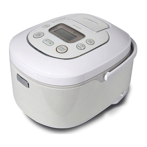
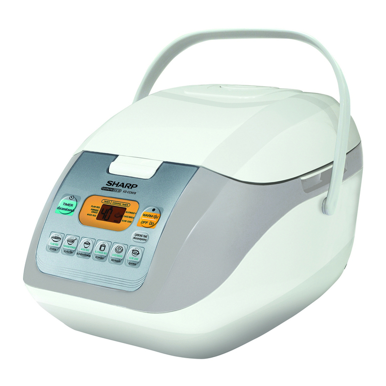
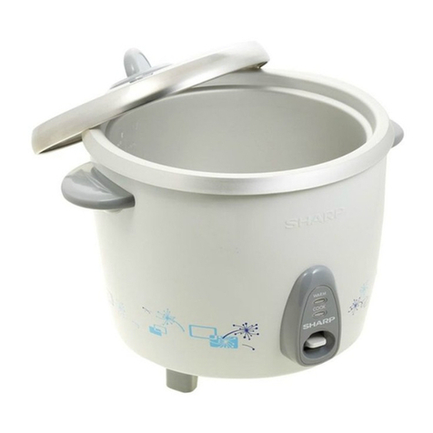
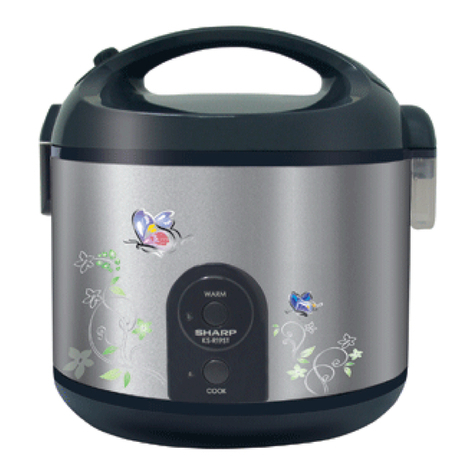
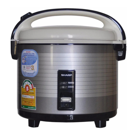
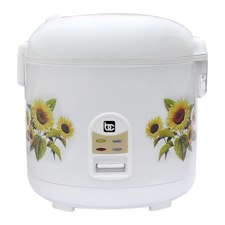
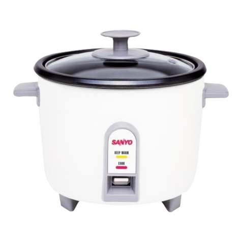
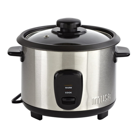
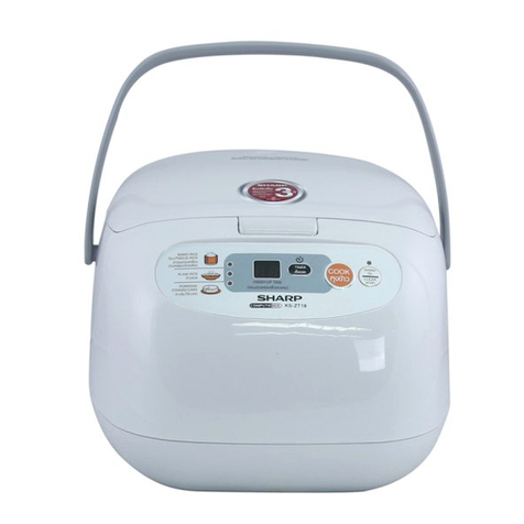
Sharp KSH-Q11 User manual

SHARP SERVICE MANUAL
SHARP CORPORATION
AUTOMATIC RICE COOKER
MODELS KSH-Q11
KSH-Q18
KSH-CANDY 11
KSH-CANDY 18
TABLE OF CONTENTS
PARTS IDENTIFICATION AND SPECIFIC INFORMATION...................................................
CAUTIONS FOR USE............................................................................................................
HOW TO CLEAN THE COOKER...........................................................................................
WIRING DIAGRAM AND CIRCUIT DIAGRAM.......................................................................
COMPONENT REPLACEMENT PROCEDURE.....................................................................
METHOD OF OPERATION.....................................................................................................
ADJUSTMENT OF SWITCH LEVER AND CONTACTS.........................................................
INSPECTION AFTER REPAIRING.........................................................................................
TESTING OPERATING CONDITION......................................................................................
PROBLEMS AND SOLUTIONS..............................................................................................
SERVICE PARTS LIST ..........................................................................................................
Page
2
3
3
4
5 - 8
9
10 - 11
12
12
13
14 - 23
In the interests of user-safety (Required by safety
regulation in some countries) the set should be
restore to its original condition and only parts identical
to those specied should be used.

2
PARTS IDENTIFICATION
Lid knob
Glass lid
Model: KSH-CANDY 11
KSH-CANDY 18
Inner pot
Handle
Outer pot
Power cord plug
Leg
Panel
Cook switch
Cook lamp indicator
Warm lamp indicator
Model : KSH-Q11
KSH-Q18
(The upper lid is stainless)
SPECIFIC INFORMATION
Model
Rated voltage (V) 220
50
Power consumption
(W)
Rice cooking
Warming
Rice cooking
capacity Min
Product dimension
(mm.)
Weight (kg)
Rated frequency (Hz)
Max
KSH-Q11
485 485
42 42
277 277
224 224
216 215
1.5 1.7
600 600
42.6 42.6
325 325
268 268
239 233
1.9 2.3
KSH-Q18 KSH-CANDY 11 KSH-CANDY 18
W
D
H
0.18 . or 1 cup 0.18 . or 1 cup
0.36 . or 2 cups 0.36 . or 2 cups
1.1 . or 6 cups 1.1 . or 6 cups
1.8 . or 10 cups 1.8 . or 10 cups

3
HOW TO CLEAN THE COOKER
Always unplug and let the rice cooker cool down before cleaning.
1. Heater plate.
Use the damp ne sandpaper to clean the dirty area and wipe out with sponge or damp cloth, then wipe again
with the dry cloth to remove the humidity.
2. Inner pot / glass lid / upper lid.
Soak inner pot, glass lid / upper lid in lukewarm water and wash with sponge, washing detergent or liquid
detergent and then wipe with dry cloth.
3. Outer pot.
Wash with sponge and wipe with cloth to dry it. Do not use any harsh cleanser or outer pot as it could crack the
surface.
CAUTIONS FOR USE
1. Keep clean the brim and bottom of inner pot, heater plate at all times to avoid sticking cooked rice, uncooked
rice grains, dust and dirt. Cooking performance may be made worse by such sticking rice grain and the like.
2. Do not use the damaged inner pot. It may cause in malfunction.
3. When warming operation is no longer required, please unplug the power cord.
4. Never push the cook switch when the inner pot with rice is not placed in, never insert any object into the switch.
It may cause a trouble.
5. After cooking is over and need to continue cooking, please wait for in order to allow about 10 minutes
thermostat resume to normal condition.
6. Take precautions against intensive vibration or impact from inadvertent handling while cooking is carried on,
which may cause malfunction of thermostat, thus the nish of cooked rice may be made worse.
7. Do not immerse the set in water or sprinkling water on the heater plate.
8. In case the power cord is broken, it must be replaced with specialized power cord or the standard power cord
made by manufacturer or appointed service providers.
9. Disconnect the plug from the wall outlet every time after use.
10. Do not use the cooker on a wet oor, under direct sunlight or near the gas stove.
11. While cooking, do not put the rice cooker on or near combustible materials such as curtains or vinyl carpets.
12. During or immediately after cooking, the areas near the steam vent hole are kept at high temperature.
Do not touch those areas to avoid burns.
13. Never connect the plug with your wet hand as it may be dangerous from electric leakage.
14. Do not use any other inner pot except the provided one.
15. Keep the rice cooker out of the children’s reach, especially when cooking rice.
16. Never share the wall outlet with other appliances.
17. Do not opening the glass lid/upper lid when during boiling because touched hot steam.
18. Insert the plug into the wall outlet rmly and when disconnecting, hold the plug and pull it out without touching
the power cord.
19. Do not use the inner pot with other heating appliances such as a gas stove. The inner pot may be transformed
and it may cause poor cooking result.
20. Do not leave the plastic spoon in the rice cooker while cooking or warming.
21. Do not disassemble or repair the cooker by yourself, it may cause troubles such as a re of electric shock.
Consult your nearest dealer.

4
WIRING DIAGRAM
CIRCUIT DIAGRAM
220V~
Micro switch
COM.
NC.
W/H
H/P
Temp. fuse
Cooking Warming

5
COMPONENT REPLACEMENT PROCEDURE
1. Turn over the rice cooker.
2. Remove 3 screws holding the bottom lid.
3. Now the bottom lid is free.
1. Remove the inner pot from the outer pot.
2. Remove the screw holding the panel from the outer pot.
3. Remove the panel from the outer pot, pull the insulator cover
and remove the neon lamp ass’y from the panel.
4. Now the panel is free.
1. Remove the inner pot from the outer pot.
2. Remove 2 screws holding handles from the outer pot.
(Model KSH-Q11, KSH-CANDY 11)
3. Remove 4 screws holding handles from the outer pot.
(Model KSH-Q18, KSH-CANDY 18)
4. Now handles are free.
REMOVE OF PANEL
REMOVE OF HANDLE
REMOVE OF BOTTOM LID
Screw
Panel
Neon lamp ass’y
Insulator cover
Outer pot
Handle
Outer pot
Screw
Screw
Bottom lid
Rice cooker
Place a blanket for protection
Fig. 3
Fig. 2
Fig. 1

6
1. Remove the bottom lid in accordance with “REMOVE OF BOTTOM LID”.
2. Remove the micro SW. in accordance with “REMOVE OF MICRO SWITCH”.
3. Use to pliers pull the stop ring holding the switch lever ass’y from the thermostat rod.
4. Remove the screw holding the switch angle ass’y from the reector.
5. Remove the switch lever ass'y from the thermostat ass'y and push inward the switch lever ass'y into the
outer pot and remove from the outer pot.
6. Now the switch lever ass’y is free.
REMOVE OF SWITCH LEVER ASSEMBLY
1. Remove the bottom lid in accordance with “REMOVE OF BOTTOM LID”.
2. Disconnect 2 terminals from the micro SW.
3. Remove the screw holding the micro SW. from the SW. angle.
4. Now the micro SW. is free.
REMOVE OF MICRO SWITCH
Fig. 5
Micro switch
Cord band
Reector
Switch lever ass’y
Screw
Stop ring
Thermo plate
Outer pot
Thermostat
Thermostat rod
Thermostat spring
12
Push inward
Remove
Terminal
Screw
Micro SW.
SW. angle
Fig. 4

7
1. Remove the bottom lid in accordance with “REMOVE OF BOTTOM LID”.
2. Remove the closed terminal holding all lead wires.
3. Disconnect the terminal from the micro SW. and remove the screw holding lead wire of warm heater ass’y
from the heater terminal.
4. Twist 2 claws of reector and remove the warm heater ass’y.
5. Now the warm heater ass’y is free.
REMOVE OF WARM HEATER ASSEMBLY
Claw of reector
Warm heater ass’y
Lead wire of warm heater ass'y
Screw
Heater terminal
Lead wire yellow Lead wire blue
Terminal
Micro SW.
1. Remove the bottom lid in accordance with “REMOVE OF BOTTOM LID”.
2. Fix the thermostat rod, pull the stop ring by using the pliers and straightening
2 claws of thermostat.
3. Remove the thermostat from the thermo plate. Fig 5.
4. Now the thermostat ass’y is free.
REMOVE OF THERMOSTAT ASSEMBLY
1. Remove the bottom lid in accordance with “REMOVE OF BOTTOM LID”.
2. Remove the screw and the nut holding the temp. fuse ass’y from the heater terminal and the plug pin.
3. Now the temp. fuse ass’y is free.
REMOVE OF TEMP. FUSE ASSEMBLY
Fig. 6
Fig. 8
Thermostat rod
Thermo plate
Stop ring
Claw of thermostat
Fig. 7
Temp. fuse ass’y
Nut
Screw
Plug pin
Heater terminal

8
1. Remove the bottom lid in accordance with “REMOVE OF BOTTOM LID”.
2. Remove the closed terminal holding for the neon lamp lead wires.
3. Cut the cord band and disconnect terminal from the micro SW.
4. Remove 2 screws holding the lead wire yellow and lead wire blue from
2 heater terminals and disconnect terminal from the micro switch.
5. Remove the screw holding the panel from the outer pot.
6. Pull the insulator cover from the panel.
7. Remove the neon lamp ass’y from the panel.
8. Now the neon lamp ass’y is free.
REMOVE OF NEON LAMP ASSEMBLY
1. Remove the bottom lid in accordance with “REMOVE OF BOTTOM LID”.
2. Remove 2 screws holding lead wires from the heater plate ass’y.
3. Remove 3 screws holding the heater plate ass’y from the reector.
4. Now the heater plate ass’y is free.
REMOVE OF HEATER PLATE ASSEMBLY
Heater plate
Screw
Screw
Screw
Reector
Outer pot
Screw
Fig. 9
Fig. 10
Outer pot
Insulator
Neon lamp ass’y
Panel
Screw
Screw
Lead wire yellow
Lead wire red
Lead wire yellow
Lead wire blue
Terminal
Micro switch
Closed terminal
Cord band
Heater
terminal

9
METHOD OF OPERATION
Different degree of temperature at various parts of the cooker during its operation.
After being switch “ON” the operation will be started by generating heat from the heater plate and spread
through the bottom of inner pot. As long as there still be water in the inner pot, the temperature at the bottom will
be always lower than 100 C.
When rice at the bottom is well cooked cause no more water left, then the temperature will sharply raise
up to certain level more than 100 C that the thermostat will automatically switch off the heater plate operation.
(As a whole process, it takes about 30 minutes.)
At this stage, rice at the top is not yet still well cooked, warm heater will automatically start working
consecutively after heater plate being switch off. It takes another 15 minutes until rice is completely in the proper
manners.
To repair rice cooker, the following parts should be carefully checked and / or repaired in the proper manners.
1. Inner pot.
Outer side : It must be cleaned without any contaminants and particles at the bottom for it can be rmly
contacted the heater plate evenly.
Inner side : It must be cleaned without dry cooked rice at the bottom, otherwise it can be the prevention of
heat transmission throughout the inner pot. And it may cause temperature at the bottom raise
up to the level which can be switched of the heater plate (as above explained) before the proper
time. So, it may cause improper rice-cooking.
2. Heater plate and thermostat.
- Ensure that there is no any contaminant or deposits on heater plate and thermostat, it will cause the operation
of switching off before the proper time.
3. Switch lever and micro switch.
- The switch lever and micro switch must be in proper alignment.
4. Cook switch.
- Cook switch must be in proper working, otherwise it may cause thermostat be unable to cut off when rice is
already cooked.
30 MINUTES
C
TEMPERATURE
TIME
THERMOSTAT CUTS OFF
HEATER PLATE
INNER POT
THERMOSTAT
RICE
100 C

10
A. Thermostat rod must not be drew up by switch lever. It should be moving left and right easily.
ADJUSTMENT OF SWITCH LEVER AND CONTACTS
1. Turn over the outer pot with inner pot inside, disclose its bottom lid. Push cook switch, adjust switch lever
and switch angle.
Bottom lid
Outer pot
Cook switch
Inner pot
Push the cook switch
Cook switch
Gap
Micro switch
Micro switch
Switch lever
Gap
Thermostat rod
Reector
Reector
Thermostat ass’y
Switch lever
Inner pot Heater plate
A
Fig. 11
Fig. 12
View B
B

11
3. Ensure the capability of up-down movement of switch lever.
2. As soon as inner pot is lifted up from outer pot, switch lever must be spring up and micro switch is pressed
completely. This rice cooker is so designed that the cook switch will not be put in “COOK” position whenever the
inner pot is taken off or not set into the cooker before use.
Micro switch
Switch lever
Cook switch
Reector
Heater plate
Thermostat spring back
Thermostat ass’y
Cook switch spring back
Switch lever
No gap
Thermo plate touch
reector
Reector
Thermostat ass’y
Fig. 13
View C
C

12
TESTING OPERATING CONDITION
1. Simplied Testing Method
1. Firmly put inner pot into the cooker, and also close the glass lid/upper lid.
2. Plug the power cord.
3. Push cook switch to check the operation of thermostat. It will cut off approximately in 3-5 minutes, which is
the standard timing.
2. Water Boiling Method
1. Fill 2 measuring cups of water in the inner pot.
2. Firmly put inner pot into the outer pot.
3. Plug the power cord.
4. Push cook switch .
5. As soon as water evaporated dry, thermostat must cut off.
3. Rice-Cooking Method
1. Fill rice and water at the maximum level of the inner pot.
2. Plug the power cord, and push cook switch.
3. After rice is already cooked and warm for 15 minutes further, check whether the rice is completely cooked.
4. Turn over the inner pot, check the cooked rice at the bottom of inner pot. If its overdone layer is slightly
light drown, the cooking operation is acceptable. In contrary, if cooked rice is brownish of uncompletely
cooked, thermostat may be fault.
INSPECTION AFTER REPAIRING
1. Cook switch should be at the center of panel.
2. Ensure that there is no any contaminants, deposits, stains exist on heater plate, thermostat and outside
bottom of inner pot.
3. Firmly put inner pot inside the cooker, move inner pot right and left to ensure it can be closely contact
with outer pot.
4. Check the operation of cook switch and thermostat.
- When inner pot is already put in, little bit right and left moveable, push cook switch, the state of cook switch
must be steadily pushed down, as soon as the inner pot is lifted up, cook switch will automatically spring up.
5. Check the operation of indicator lamp and cook switch connection.
5.1 Plug the power cord.
5.2 Check the state of indicator lamp when push “COOK” switch and “WARM”.
5.3 Put the inner pot into the cooker, push cook switch. Ensure that the inner pot can be rmly contacted with the
heater plate.

13
PROBLEMS AND SOLUTIONS
1. Incompletely cooked
rice.
2. Unevenly cooked
rice.
3. Waterish uncooked
rice.
4. Overdone brown
rice.
5. Cook indicator
lamp not go “ON”.
6. Cook indicator lamp
go “ON” but failure
of heat conduction.
7. Failure warming.
1. Warm indicator
not go “ON”.
2. Failure to keep
warm.
1. Inner pot improperly
contacted with heater
plate.
2. Failure in setting inner
pot.
3. Faulty thermostat.
4. Dirty heater plate.
1. Deformed inner pot.
2. Dirty heater plate.
1. Faulty thermostat.
2. Faulty switch.
3. Deformed inner pot or
heater plate.
1. Malfunction of switch
lever.
2. Faulty thermostat.
3. Deformed inner pot or
heater plate.
1. Disconnected power cord.
2. Faulty wiring.
3. Malfunction of switch.
4. Disconnected resistor.
1. Faulty wiring.
2. Faulty heater plate.
1. Burned-out wire.
2. Faulty warm heater.
1. Faulty warm heater.
2. Disconnected wiring.
1. Adjust or replace. Boil about 800 cc. of
water. Check the state
of bubbles at the bottom
of inner pot.
If bubbles rise up evenly
around the bottom, it is
acceptable.
2. Adjust.
3. Replace.
4. Clean.
1. Replace.
2. Clean.
1. Replace.
2. Adjust or replace.
3. Replace.
1. Adjust or replace.
2. Replace.
3. Replace.
1. Repair.
2. Repair.
3. Adjust or replace.
4. Replace.
1. Repair.
2. Replace.
1. Replace.
2. Replace.
1. Replace.
2. Repair.
Problems Possible causes Solution Check
Acceptable
Unacceptable

REF. NO PARTS CODE DESCRIPTION Q’TY PRICE
(FEC)
PRINTING & PACKAGING MATERIAL
1-1 11A103 INSTRUCTION BOOK 1
1-2 11A101 SET PACKING CASE 1
1-3 11A102 CARTON BOX 1
1-4 21A5062 MEASURING CUP 1
1-5 11A104 BOTTOM PAD 2
1-6 11A105 UPPER PAD 2
MECHANICAL PARTS
2-1 11A301BLASY UPPER LID ASS’Y Blue 1
11A301GRASY UPPER LID ASS’Y Green 1
11A301ORASY UPPER LID ASS’Y Orange 1
11A301PASY UPPER LID ASS’Y Pink 1
11A301VLASY UPPER LID ASS’Y Violet 1
2-1-1 11A301 UPPER LID 1
2-1-2 11A201BL LID KNOB Blue 1
11A201GR LID KNOB Green 1
11A201OR LID KNOB Orange 1
11A201P LID KNOB Pink 1
11A201VL LID KNOB Violet 1
2-1-3 1U1532 LID KNOB BUSH 1
2-1-4 1U1042 KNOB SCREW 1
2-2 11A302 INNER POT 1
2-3 11A303BJ OUTER POT BJ 1
11A303ER OUTER POT ER 1
11A303OT OUTER POT OT 1
11A303PH OUTER POT PH 1
11A303VS OUTER POT VS 1
2-4 11A202BL HANDLE Blue 2
11A202GR HANDLE Green 2
11A202OR HANDLE Orange 2
11A202P HANDLE Pink 2
11A202VL HANDLE Violet 2
2-5 11A203BLASY PANEL ASS’Y Blue 1
11A203GRASY PANEL ASS’Y Green 1
11A203ORASY PANEL ASS’Y Orange 1
11A203PASY PANEL ASS’Y Pink 1
11A203VLASY PANEL ASS’Y Violet 1
2-6 11A205 INSULATOR COVER 1
2-7 1B2031 THERMOSTAT SPRING 1
2-8 1A2051 THERMO PLATE 1
2-9 11A391SET SWITCH SET 1
2-10 11A305BLASY BOTTOM LID ASS’Y Blue 1
11A305GRASY BOTTOM LID ASS’Y Green 1
11A305ORASY BOTTOM LID ASS’Y Orange 1
11A305PASY BOTTOM LID ASS’Y Pink 1
11A305VLASY BOTTOM LID ASS’Y Violet 1
2-11 1A492UASY PLUG INSULATOR ASS’Y 1
SERVICE PARTS LIST
Model : KSH-Q11
14

REF. NO PARTS CODE DESCRIPTION Q’TY PRICE
(FEC)
ELECTRIC PARTS
3-1 1B4934ASY POWER CORD ASS’Y 1
3-2 1A2014 HEATER PLATE ASS’Y 1
3-3 1A2021ASY THERMOSTAT ASS’Y 1
3-4 11A402ASY NEON LAMP ASS’Y 1
3-5 1A2394 TEMP. FUSE ASS’Y 1
3-6 11A401 WARM HEATER ASS’Y 1
3-7 2A410 MICRO SWITCH 1
15

REF. NO PARTS CODE DESCRIPTION Q’TY PRICE
(FEC)
PRINTING & PACKAGING MATERIAL
1-1 11A113 INSTRUCTION BOOK 1
1-2 11A110GA SET PACKING CASE GA = Green Apple 1
11A110SK SET PACKING CASE SK = Sunkizt Orange 1
1-3 11A112GA CARTON BOX GA = Green Apple 1
11A112SK CARTON BOX SK = Sunkizt Orange 1
1-4 21A5062 MEASURING CUP 1
1-5 11A104 BOTTOM PAD 2
1-6 11A105 UPPER PAD 2
MECHANICAL PARTS
2-1 11A702ASY GLASS LID ASS’Y 1
2-1-1 11A702 GLASS LID 1
2-1-2 11A201B LID KNOB Black 1
2-1-3 1B501V LID KNOB BUSH 1
2-1-4 130U0414A KNOB SCREW 1
2-2 11A302 INNER POT 1
2-3 11A303GA OUTER POT GA = Green Apple 1
11A303SK OUTER POT SK = Sunkizt Orange 1
2-4 11A202B HANDLE Black 2
2-5 11A203GAASY PANEL ASS’Y GA = Green Apple 1
11A203SKASY PANEL ASS’Y SK = Sunkizt Orange 1
2-6 11A205 INSULATOR COVER 1
2-7 1B2031 THERMOSTAT SPRING 1
2-8 1A2051 THERMO PLATE 1
2-9 11A391SET SWITCH SET 1
2-10 11A305BASY BOTTOM LID ASS’Y Black 1
2-11 1A492UASY PLUG INSULATOR ASS’Y 1
ELECTRIC PARTS
3-1 1B4934ASY POWER CORD ASS’Y 1
3-2 1A2014 HEATER PLATE ASS’Y 1
3-3 1A2021ASY THERMOSTAT ASS’Y 1
3-4 11A402ASY NEON LAMP ASS’Y 1
3-5 1A2394 TEMP. FUSE ASS’Y 1
3-6 11A401 WARM HEATER ASS’Y 1
3-7 2A410 MICRO SWITCH 1
Model : KSH-CANDY 11
16

Model : KSH-Q18
REF. NO PARTS CODE DESCRIPTION Q’TY PRICE
(FEC)
PRINTING & PACKAGING MATERIAL
1-1 11A103 INSTRUCTION BOOK 1
1-2 11B101 SET PACKING CASE 1
1-3 11B102 CARTON BOX 1
1-4 21A5062 MEASURING CUP 1
1-5 11B104 BOTTOM PAD 2
1-6 11B105 UPPER PAD 2
MECHANICAL PARTS
2-1 11B301BLASY UPPER LID ASS’Y Blue 1
11B301GRASY UPPER LID ASS’Y Green 1
11B301ORASY UPPER LID ASS’Y Orange 1
11B301PASY UPPER LID ASS’Y Pink 1
11B301VLASY UPPER LID ASS’Y Violet 1
2-1-1 11B301 UPPER LID 1
2-1-2 11B201BL LID KNOB Blue 1
11B201GR LID KNOB Green 1
11B201OR LID KNOB Orange 1
11B201P LID KNOB Pink 1
11B201VL LID KNOB Violet 1
2-1-3 1B1531 LID KNOB BUSH 1
2-1-4 1A1043 KNOB SCREW 1
2-2 11B302 INNER POT 1
2-3 11B303BJ OUTER POT BJ 1
11B303ER OUTER POT ER 1
11B303OT OUTER POT OT 1
11B303PH OUTER POT PH 1
11B303VS OUTER POT VS 1
2-4 11B202BL HANDLE Blue 2
11B202GR HANDLE Green 2
11B202OR HANDLE Orange 2
11B202P HANDLE Pink 2
11B202VL HANDLE Violet 2
2-5 11B203BLASY PANEL ASS’Y Blue 1
11B203GRASY PANEL ASS’Y Green 1
11B203ORASY PANEL ASS’Y Orange 1
11B203PASY PANEL ASS’Y Pink 1
11B203VLASY PANEL ASS’Y Violet 1
2-6 11A205 INSULATOR COVER 1
2-7 1B2031 THERMOSTAT SPRING 1
2-8 1A2051 THERMO PLATE 1
2-9 11B391SET SWITCH SET 1
2-10 11B305BLASY BOTTOM LID ASS’Y Blue 1
11B305GRASY BOTTOM LID ASS’Y Green 1
11B305ORASY BOTTOM LID ASS’Y Orange 1
11B305PASY BOTTOM LID ASS’Y Pink 1
11B305VLASY BOTTOM LID ASS’Y Violet 1
2-11 1A492UASY PLUG INSULATOR ASS’Y 1
17

REF. NO PARTS CODE DESCRIPTION Q’TY PRICE
(FEC)
ELECTRIC PARTS
3-1 1B4934ASY POWER CORD ASS’Y 1
3-2 1B2012 HEATER PLATE ASS’Y 1
3-3 1A2021ASY THERMOSTAT ASS’Y 1
3-4 11B402ASY NEON LAMP ASS’Y 1
3-5 1C2392 TEMP. FUSE ASS’Y 1
3-6 1B4201 WARM HEATER ASS’Y 1
3-7 2A410 MICRO SWITCH 1
18

REF. NO PARTS CODE DESCRIPTION Q’TY PRICE
(FEC)
PRINTING & PACKAGING MATERIAL
1-1 11A113 INSTRUCTION BOOK 1
1-2 11B110GA SET PACKING CASE GA = Green Apple 1
11B110SK SET PACKING CASE SK = Sunkizt Orange 1
1-3 11B112GA CARTON BOX GA = Green Apple 1
11B112SK CARTON BOX SK = Sunkizt Orange 1
1-4 21A5062 MEASURING CUP 1
1-5 11B104 BOTTOM PAD 2
1-6 11B105 UPPER PAD 2
MECHANICAL PARTS
2-1 11B702ASY GLASS LID ASS’Y 1
2-1-1 11B702 GLASS LID 1
2-1-2 11B201B LID KNOB Black 1
2-1-3 1B501V LID KNOB BUSH 1
2-1-4 130U0616A KNOB SCREW 1
2-2 11B302 INNER POT 1
2-3 11B303GA OUTER POT GA = Green Apple 1
11B303SK OUTER POT SK = Sunkizt Orange 1
2-4 11B202B HANDLE Black 2
2-5 11B203GAASY PANEL ASS’Y GA = Green Apple 1
11B203SKASY PANEL ASS’Y SK = Sunkizt Orange 1
2-6 11A205 INSULATOR COVER 1
2-7 1B2031 THERMOSTAT SPRING 1
2-8 1A2051 THERMO PLATE 1
2-9 11B391SET SWITCH SET 1
2-10 11B305BASY BOTTOM LID ASS’Y Black 1
2-11 1A492UASY PLUG INSULATOR ASS’Y 1
ELECTRIC PARTS
3-1 1B4934ASY POWER CORD ASS’Y 1
3-2 1B2012 HEATER PLATE ASS’Y 1
3-3 1A2021ASY THERMOSTAT ASS’Y 1
3-4 11B402ASY NEON LAMP ASS’Y 1
3-5 1C2392 TEMP. FUSE ASS’Y 1
3-6 1B4201 WARM HEATER ASS’Y 1
3-7 2A410 MICRO SWITCH 1
Model : KSH-CANDY 18
19

E
C
6
2
F
B
2
H
5
H
3
1 4
E
A
G
F
5
A
3
D D
6
B
C
G
41
1-4
2-2
3-2
3-3 2-10
3-7
3-6
2-11
2-8
2-7
3-5
2-3
3-4
2-6
2-9
2-4
2-1-2
2-1-1
2-1
2-1-3
2-1-4
2-5
KSH-Q11
3-1
20
This manual suits for next models
3
Table of contents
Other Sharp Rice Cooker manuals

Sharp
Sharp KS-COM18 User manual

Sharp
Sharp KSH-106 User manual

Sharp
Sharp KSH-777/T User manual

Sharp
Sharp KS-1800 User manual

Sharp
Sharp KS-R19S User manual

Sharp
Sharp KS-M102 User manual

Sharp
Sharp KS-ZA10HH User manual

Sharp
Sharp KS-COM183MV-WH User manual

Sharp
Sharp KS-18EV User manual

Sharp
Sharp KS-ZA10HH User manual