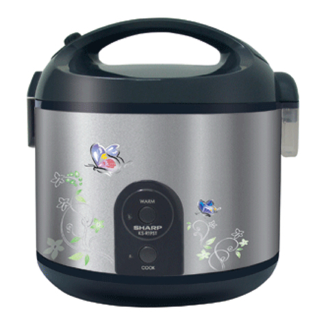
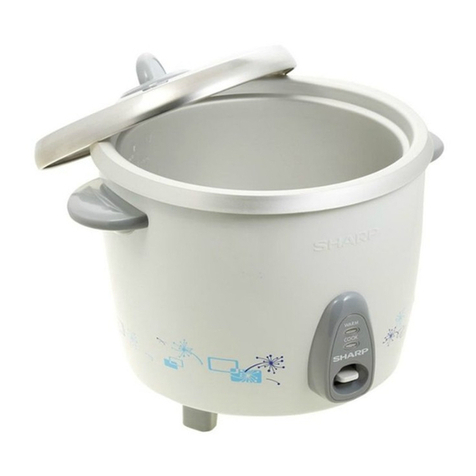
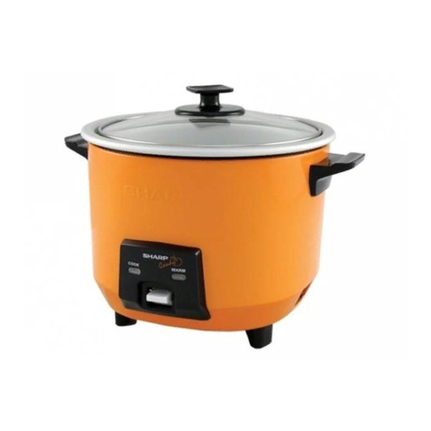
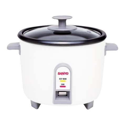
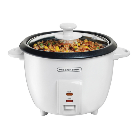
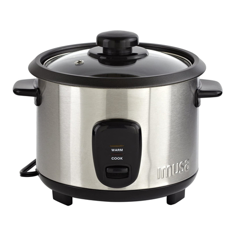
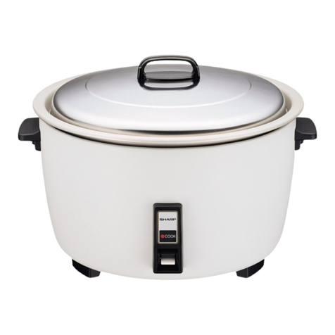
Sharp KS-18EV User manual

SHARP CORPORATION
SHARP SERVICE MANUAL
TABLE OF CONTENTS
PARTS IDENTIFICATION AND SPECIFIC INFORMATION ......................................................
CAUTIONS FOR USE ...............................................................................................................
CLEANING AND CARE .............................................................................................................
WIRING DIAGRAM AND CIRCUIT DIAGRAM ..........................................................................
COMPONENT REPLACEMENT PROCEDURE .......................................................................
INSPECTION AFTER ASSEMBLING .......................................................................................
SIMPLIFIED TESTING METHOD .............................................................................................
PRECAUTIONS FOR WARM-KEEPING TO GET TASTY RICE ..............................................
TROUBLESHOOTING ..............................................................................................................
Page
2
3
4
5
6 - 11
12 - 13
14 - 15
16
17 - 18
JAR RICE COOKER
MODELS KS-18EV / ETV
KS-181EV / ETV
KS-182ETV
In the interests of user-safety (Required by safety
regulations in some countries) the set should be restore
to its original condition and only parts identical to those
specified should be used.

2
PARTS IDENTIFICATION
Handle cover
Latch button
WARM switch and
WARM indicator lamp
COOK switch and
COOK indicator lamp
Lid
Switch button
Steam vent hole
Inner lid Latch angle
Inner pot
Spoon box Body
SPECIFIC INFORMATION
Power supply cord
Control panel
Bottom cover
Thermostat
Heater plate
Model
Rated voltage (V)
Power consumption (Cook) (W)
Power consumption (Warm) (W)
Capacity (l)
Heating method
Outside dimension (W x D x H) (mm.)
Weight (Approx.) (kg)
KS-18EV / ETV KS-181EV / ETV KS-182ETV
220
600
25
1.8
Direct heating method
308 x 285 x 306
3.1
Dew receiver
Latch hook
cover
Control panel
COOK
WARM

3
CAUTIONS FOR USE
Never share the wall outlet with other appliances.
Insert the plug into the wall outlet firmly and when disconnecting, hold the plug and pull it out without touching
the power cord.
In case the power cord is broken, it must be replaced by manufacturer or appointed service providers or
equivalent professionals to avoid any damages.
Do not immerse the set in water or sprinkling water on the heater plate.
If the switch is turned off prematurely resulting in cook failure, do not attempt to keep the switch pressed
forcibly. Malfunction may occur. The possible cause of premature turning-off of the switch is rice sticking to the
bottom of inner pot or the heater plate.
Keep the switch away from tableware.
Do not put the cooker on a wet floor, under direct sunlight or near the gas stove.
Never connect the plug with your wet hand, it may expose you to electric shock. Disconnect the plug from the
wall outlet when not using the cooker.
Children should be supervised to ensure that they do not play with the cooker.
This cooker is not intended for use by persons (including children) with reduced physical, sensory or mental
capability, or lack of experience and knowledge. Unless they have been given supervision or instruction
concerning the use of the cooker by a person who will responsible for their safety.
This cooker is intended to be used in household and similar locations such as:
- Staff kitchen areas in shops, offices, and other working environments;
- By guests in the hotels, motels and other residential type of environments;
- Bed and breakfast type of environments.
Do not open the lid while cooking to avoid hot steam.
Do not use the inner pot with other heating appliances such as a gas stove. The inner pot may be transformed
and result in poor cooking food.
Do not give strong vibration of impact during cooking. It may cause an irregular operation-of thermostat to lead
to poor rice-cooker.
Always keep the surface of inner pot, heater plate and inner lid clean.
Do not place wiping cloth on the lid or the handle when using.
This model is for rice cooking and heat retention. Do not use it as follows. Boiling-over or smell permeation will
occur.
“Heat retention of food (boiling rice, steamed rice with red beans) which spoils quickly”.
“Cooking and heat retention and addition of cool boiled rice”. Heat retention with plastic spoon put in the rice
cooker”.
Be sure to put the steam tube and inner lid when using, otherwise cooking failure or poor heat retention may
occur.
Do not turn the rice cooker on with out both rice and water in the inner pot.
Do not disassemble or repair the cooker by yourself. It may cause damage or accident such as fire or electric
shock. Please consult your nearest dealer.
Do not use metal spoon which may scratch the inner pot.
Do not use any other inner pot except the provided one.
Connect the plug to the wall outlet properly to disconnect, hold the plug head only and pull it out. Do not pull
the power cord.
Do not shake or drop the cooker when cooking, thermostat may be malfunctioned and result in poor cooking
food.
During or immediately after cooking, do not touch the area near the steam vent, the hot steam may cause
burns.
When cooking, do not place the cooker on or near the combustible materials such as curtains or vinyl carpets.

4
CLEANING AND CARE
Always disconnect the plug from the wall outlet and let the cooker to cool down first before cleaning. Be
sure to use only the tableware detergent, and do not use nylon scrubbing brush which may cause cracks
and rusts.
Use dry cloth to clean the body and lid.
Do not shower or soak the cooker in the water.
Remove the dew receiver from the cooker, clean it with a sponge or brush, and dry it with a cloth.
Use a fine sandpaper, slightly wet it to clean the dirty area, wipe off with a sponge, then dry it
with a cloth.
Use a sponge to wash the inner pot and inner lid.
To remove smell after cleaning, soak in boiling water for 30 minutes, and dry it with a cloth.
Body / Lid
Dew receiver
Heater plate / Thermostat
Inner pot / Inner lid

WIRING DIAGRAM
CIRCUIT DIAGRAM
5
Cooking
Cord reel
220V~ H/P S/H
Micro switch
Temp. fuse
Warming
COM NC.
Closed terminal
Temp. fuse angle
Tube- TA Neon lamp ass’y
Tube-NA
Temp. fuse ass’y
Terminal
AMP (I)
Connector P-2
To body
To outer pot
Cord reel ass’y
Heater plate ass’y
Connecting ring
Side heater ass’y
Micro SW.
COM
NC
To TRS angle

6
COMPONENT REPLACEMENT PROCEDURE
1. Upside down the rice cooker.
2. Remove the screw holding the cord reel ass’y.
3. Remove the screw holding the contact plate cover from the cord reel ass’y.
4. Disconnect lead wires from cord reel ass’y.
5. Now the cord reel ass’y is free.
Fig. 1
Screw Screw
Contact plate cover
Lead wire
Earth lead wire
Place a blanket for protection
Cord reel ass’y
Rice cooker
Bottom cover
REMOVE OF CORD REEL ASSEMBLY
1. Remove the cord reel assembly in accordance with “REMOVE OF CORD REELASSEMBLY”.
2. Remove the screw holding the body from bottom cover.
3. Insert the flat type screwdriver into the gap between the bottom cover and body, to pry the bottom cover
out of body.
4. Now the bottom cover is free.
REMOVE OF BOTTOM COVER
Body
Bottom cover
Fig. 2
Screw
Body
Flat type screwdriver
With this claw being pressed inward

7
1. Remove the bottom cover in accordance with “REMOVE OF BOTTOM COVER”.
2. Upside down the rice cooker and disconnect lead wires from the micro switch.
3. Remove the screw holding the micro SW. from the switch leg ass’y.
4. Now the micro SW. is free.
REMOVE OF MICRO SWITCH
Fig. 3
Micro SW.
Screw
Switch leg ass’y
Blue lead wire
Red lead wire
Yellow lead wire
Yellow lead wire
1. Remove the bottom cover in accordance with “REMOVE OF BOTTOM COVER”.
2. Remove the micro switch in accordance with “REMOVE OF MICRO SWITCH”.
3. Use to pliers pull the stop ring holding the switch leg ass’y from the thermostat rod.
4. Remove 2 screws holding the switch leg ass’y from the outer pot.
5. Now the switch leg ass’y is free.
Note : When mounting the switch assembly, lock it in a manner that the switch button will not come in contact
with the panel.
REMOVE OF SWITCH LEG ASSEMBLY
Thermostat ass’y
Outer pot
Switch leg ass’y
Thermostat rod
Stop ring
Screw
Fig. 4
1. Remove the bottom cover in accordance with “REMOVE OF BOTTOM COVER”.
2. Fixing the thermostat rod, pull the stop ring by using the pliers and straightening 2 claws of thermostat.
3. Remove the thermostat from the outer pot. (Fig. 4)
4. Now the thermostat ass’y is free.
REMOVE OF THERMOSTAT ASSEMBLY

1. Upside down the rice cooker with inner pot inside.
2. Remove the bottom cover in accordance with “REMOVE OF BOTTOM COVER”.
3. Remove 2 screws holding the lead wires
from the heater plate ass’y.
4. Remove 3 screws holding the heater
plate ass’y from the outer pot.
5. Now the heater plate ass’y is free.
Heater plate ass’y
REMOVE OF HEATER PLATE ASSEMBLY
Screw
Outer pot
Screw Fig. 5
8
1. Remove the bottom cover in accordance with “REMOVE OF BOTTOM COVER”.
2. Disconnect lead wires of the control panel.
3. Remove the nut holding the earth lead wire from the body.
4. Insert the flat type screwdriver into the gap between the upper ring and the latch hook cover, to pry the latch
hook cover from the upper ring.
5. Detach the dew receiver from the upper ring.
6. Insert the flat type screwdriver or similar to pry the claw of the hinge cover and remove it.
7. Remove 2 screws holding from the body.
8. Separate the body from the upper ring by rubber hammer knock the upper ring. (Fig. 6)
9. Remove the control panel in accordance with “REMOVE OF CONTROL PANEL”.
10.Now the body is free.
REMOVE OF BODY
Fig. 6
Latch hook cover
Body
Upper ring
Flat type screwdriver
Hinge cover
Dew receiver
Screw
Control panel
Body
Screw
Nut
(for earth lead wire)
Latch hook cover
Body
Flat type screwdriver
Upper ring
To knock

9
1
REMOVE OF CONTROL PANEL
1. Remove the body in accordance with “REMOVE OF BODY”.
2. Pry claws of the body lift up by a flat type screwdriver or similar.
3. Remove the control panel from the body (position and position ).
4. Now the control panel is free. (Fig. 7)
After disengaging the claws, push up the control panel ward the lid, pull upper part (bottom side) to this
side and pull up to remove the control panel. (Fig. 8)
12
Note : When reassembly, bend the body pawl as it was.
Fig. 8
2
Removal Assembly
1
2
Fig. 7
Flat type screwdriver
Control panel
REMOVE OF SIDE HEATER ASSEMBLY
Fig. 9
Outer pot
Side heater ass’y
1. Remove the body in accordance with “REMOVE OF BODY”.
2. Disconnect lead wires of side heater assembly from the heater plate ass’y and the micro SW., then remove
the closed terminal from the lead wire of side heater assembly.
3. Pull out the side heater ass’y from the outer pot.
Note : Before removing, put a mark for positioning of side heater ass’y on the outer pot and be sure to
reassembly, the side heater ass’y as it was.

10
1. Detach the dew receiver from the upper ring.
2. Insert the flat type screwdriver or similar into the gap between the upper ring and the hinge cover,
remove the hinge cover.
3. Fixing the handle shaft by using pliers, remove the handle shaft from the lid ass’y.
4. Now the lid ass’y is free.
REMOVE OF LID ASSEMBLY
Fig. 11
Pliers
Hammer
Lid cover
Upper ring
Handle shaft
Hinge cover
Body Flat type screwdriver
1. Remove the body in accordance with “REMOVE OF BODY”.
2. Disconnect the lead wire from heater plate ass’y and remove the screw holding temp. fuse angle.
3. Remove the temp. fuse ass’y from the temp. fuse angle.
4. Now the temp fuse ass’y is free.
Note : When reassembly take care so that the charged part of temperature fuse assembly does not protrude
from the TUBE-TA and securely fix it to the temperature fuse angle and then fix it with a screw to the
outer pot.
REMOVE OF TEMP. FUSE ASSEMBLY
Outer pot
TRS angle
Temp. fuse
Temp. fuse angle
Screw
Fig. 10

11
1. Remove the lid assembly in accordance with “REMOVE OF LID ASSEMBLY”.
2. Insert 2 pieces of plastic ruler into the gap between the lid and the lid cover, taking care not to damage
the lid. Then remove the lid away from the lid cover.
3. Separate the lid cover from the lid.
4. Now the lid assembly is free.
DISASSEMBLING THE LID ASSEMBLY
Fig. 12
Holder plate
Lid cover
Lid
1. Remove the body in accordance with “REMOVE OF BODY”.
2. Remove the lid assembly in accordance with “REMOVE OF LID ASSEMBLY”.
3. Upside down the outer pot, straighter 4 claws of outer pot holding to the upper ring.
4. Remove the outer pot from the upper ring.
5. Now the upper ring is free.
REMOVE OF UPPER RING
Outer pot
Upper ring
Outer pot
Claw of outer pot
Fig. 13

Basic requirement for cooking is to maintain the close contact of inner pot bottom with heater plate and
thermostat. AstheJARRICECOOKERisofdirectheatingtype,whenthetemperatureofinnerpotbottomreaches
141oC to 149oC, the thermostat will operate to provide change-over to warm-keeping automatically.
Therefore,the cooker can beputin use in anexcellentcondition if theinnerpot bottom is keptcontactclosely with
theheaterplateandputina stable state. It is the basic requirement forthe direct heatingtype cooking.Accordingly,
if the cooker is used under the unstable state of close contact, it will become the causes of early power
OFF, discoloration and deformation of heater plate or other troubles. Also, any deformed or
contaminant-deposited inner pot and heater plate may lead to early power OFF or other troubles. Further to the
above, this JAR RICE COOKER is so designed that the cook switch will not be put in “COOK” position whenever
the inner pot is taken off or not set into the cooker before use, hence this point must be well noted when
adjusting the switch. Upon completion of repairing work, inspect the cooker as to the following points without fail.
INSPECTION AFTER ASSEMBLING
Center adjustment and confirmation of switch leg ass’y
1. For the center adjustment, align not with the thermostat rod, but with the hole of the outer pot.
(Carry out this work with particular strictness and care.)
2. Adjust in such a manner that, when the switch leg ass’y held by hand as in Fig.14 is lightly swung to the
left and right, it moves in a perfect symmetry with respect to the hole of the outer pot.
3. The switch button should be at the center of the panel hole.
Verification of Work and Function
1. Is there any part left uninstalled or any wrong wiring?
2. Is the center adjustment of the switch leg ass’y as specified?
3. Finally, energize for confirmation. (JAR RICE COOKER should be checked in the erected state.)
a. Is the state “WARM” achieved when the inner pot is detached, with the cook switch set to “COOK”?
b. Does “COOK” and “WARM” indicator lamp not flicker, when the switch button is gently vibrated, with the
switch set to “WARM”?
c. Does “COOK” and “WARM” indicator lamp not flicker, when the switch button is gently vibrated up and
down, with the cook switch set to “COOK”?
d. Is there no possibility that the cook switch is turned ON, even when the switch button is depressed
without placing the inner pot?
e. Is the thermostat functioning perfectly?
f. Is the indicator lamp lit normally?
12
Measurement of Insulation Resistance
1. Insulation resistance.
Should be more than 1 Mupon measurement by a 500V d.c. megger (Check before and immediately after
the temperature test).
2. Dielectric strength.
Should be free from defects at 1000V a.c. for one min. with the cook switch set to “COOK” take
measurements on the pins of the plug socket and also on each of the heater plate ass’y and bottom lid.
(To be carried out after the insulation resistance measurement which is taken immediately after the
temperature test.) Stop to be measured.
With the cook switch set to “COOK”, take measurement on the blades of the plug socket and also on
each of the heater plate ass’y and cord reel ass’y.

13
Fig. 16
Thermostat rod
Outer pot hole
Switch leg ass’y
Center of outer pot
Lever to be swung
symmetrically
Stop ring
Switch leg ass’y
Thermostat rod
Fig. 17
Temperature test
Based on the temperature testing method explained earlier ensure proper performance for “COOK” and “WARM”.
Inner pot
Outer pot ass’y
Work bench
Fig. 14 Fig. 15
Thermostat ass’y
Outer pot ass’y
Inner pot
Heater plate ass’y
Inner pot to be normally in contact with

14
2. Testing procedure
a. Fill the inner pot with 80 ml. of water turn ON the cook switch (for cooking purpose) to energize the
cooker, and measure the time for cooking.
b. When steam comes out of the steam vent, open the upper lid and check the bubbling state on the
bottom of inner pot. (Check if the inner pot is allowed to be in close and stable contact with the heater
plate. Conduct checking within a short period of time so as not to influence over the operating time.)
c. Where the bubbling state is satisfactory, close the upper lid again and energize the cooker.
3. Judgment criteria
During the course of the simulated cooking with water conducted under the conditions as above, if meeting
the following requirements, will be considered acceptable.
a. If the bubbling state is such that bubbles occur evenly around the bottom of inner pot as shown in
Fig. 19(A), the inner pot is satisfactorily in contact with the heater plate. Where bubbles do not occur more
than 1/3 of the bottom periphery as shown in Fig. 19(B), contaminant deposits on the heater plate or
deformation or damage on the inner pot may be existing. (Though such containment deposits can be
removed by cleaning, the inner pot deformed to the extent hardly rectified should be replaced with new
one. The same applies to the heater plate deformed.)
In case satisfactory cooking of rice is not accomplished (excessively overdone), conduct the temperature test
in accordance with the following procedure.
Simplified Testing Method. (Simulated Rice-Cooking)
1. Testing conditions
a. Power voltage 220V.
b. Fill inner pot with 80 ml. of water. (Water temperature to be the same as ambient temperature.)
c. Ambient temperature to be 20 to 30oC.
d. JAR RICE COOKER to be sufficiently kept cooled. (Cooker body temperature to be the same as ambient
temperature.)
e. Never fail to set the inner lid.
SIMPLIFIED TESTING METHOD
Fig. 18
Good State of Bubbling
(A)
Pot bottom
Bubbles
Poor State of Bubbling
(B)
Fig. 19
Lid
Inner pot
Water for testing
Thermostat ass’y
Inner lid
Heater plate ass’y

b. When the lid is opened immediately after the cook switch is turned OFF, no water should remain in the
inner pot, or only a small amount of water (approximately 20 cc) is to remain in the recess around the
outer periphery of the bottom face of the inner pot.
c. The time required for the cook switch to be turned OFF is in the values as given in the table below.
Note : As this test is nothing but a simplified procedure, it should be noted that operating time varied
depending on different conditions such as difference between water temperature and ambient
temperature, variations in the quantity of water, etc. Where any delicate non-conference such as the
operating time being slightly higher than that shown in tables is observed as a result of the test, it is
recommended to conduct practical rice-cooking test.
Practical Rice-Cooking Test
1. Testing conditions
a. Power voltage 220V.
b. Cooking 3 cups of rice. (Minimum)
c. Ambient temperature to be 20oC to 30oC.
d. Water to be maintained at standard level on the level gauge.
2. Judgement criteria
a. Individual lamp and switch to be turned as follows.
Cook indicator lamp goes ON.
Cook switch OFF (after 20 to 30 minutes).
Warm indicator lamp goes ON.
b. Check the rice layer on the pot bottom for the overdone degree.
Light overdone layer-Normal.
Heavy overdone layer-Replace thermostat ass’y.
3. Measurement of Warm-Keeping Temperature
At the empty state of inner pot, insert a bar-type thermometer, 100oC in full-scale into the inner pot, set the
inner lid and lid, and put the cook switch to “COOK” position. After the cooker is energized for about
2 minutes manually turn the cook switch only to “WARM” position to put the rice in warm-keeping state
for about an hour. In this case, the reading of warm-keeping temperature on the bar-type thermometer, if
within the following temperature range, will be acceptable.
15
Model Time
KS-18EV / ETV
KS-181EV / ETV
KS-182ETV
10 minutes (approx.)
Approx. 30 mm.
A jig made from fragment of packing case
100oC Bar-type Thermometer
Inner pot
Fig. 20

PRECAUTIONS FOR WARM-KEEPING TO GET TASTY RICE
Help yourself to the tasty rice under the proper use and maintenance of JAR RICE COOKER.
Major Trouble Recommended Use and Maintenance
(Cautionary Instructions)
Before cooking, wash rice thoroughly.
Take precautions against specific rice (vitaminized rice, barley, extra-old
rice, etc.) having a peculiar and strong smell.
Refrain from using excessively turbid or smelling water as far as
practicable.
After steaming, unbind sufficiently the uneven or stick mass of rice.
(For warm-keeping to the tasty rice, sufficient loosening and exposure
to air are needed.)
Be sure that latch button is kept engaged.
Use inner lid without fail.
Handle inner pot, inner lid, etc. carefully. (Any deformed part may cause
the cooker to be less tight and influence over the performance.)
Do not leave any spoon inside the pot or put any napkin over the inner
pot when in use.
Allow warm-keeping to be limited to 5 hours max.
Do not add the separately cooked rice over the rice under warm-keeping.
Do not conduct warm-keeping of a small volume of rice.
Under warm-keeping.
Refrain from warm-keeping or addition of cooled rice.
For warm-keeping, necessarily cover the rice with the lid and switch ON.
If the rice smells even under normal cooker and operation as well as
proper temperature, then conduct sterilization and disinfection in
accordance with the following procedure since such smell appears to
be caused by microbes. (Provided that, a method under the following
Note : “In Case the Rice Smells” is recommended to the customers
because the following procedure may cause the fur and the like to
remain on the bottom of inner pot, making them uncomfortable.)
Pour approx. 200 c.c. of water into the inner pot, close the upper lid
(together with inner lid without fail), turn ON cook switch, and keep
the cooker energized until the cook switch has been turned OFF.
Thereafter, wash the inner pot, cartridge, etc. thoroughly with water and
wipe them up to be dried sufficiently, Wipe out any stains remaining on
the cooker body and outer lid completely with well-wrung cloth wetted
with hot water. (IMPORTANT : NEVER WASH COOKER BODY WITH
WATER).
Refrain from using the cooker outer than for rice cooking and warm-
keeping purposes.
Note : In Case the Rice Smells.
Immerse the inner pot and inner lid into hot water for 30 to 60 minutes. Also, wipe up the cooker
body and the underside of the inner lid thoroughly with well-wrung napkin wetted with hot water and
them sterilize them under direct sunlight for 2 to 3 hours.
16
Smelling Dewing Sticking Drying
Discoloring

17
* Cook switch “ON”.
* Plugged into the wall outlet.
Replace temperature fuse
assembly and faulty parts.
Repair or replace cord reel
assembly.
Repair or replace cord reel
assembly.
Correct wiring.
Repair or replace it.
Replace heater plate.
Repair or replace faulty parts.
* Advise proper operating
instructions.
Replace inner pot or faulty parts.
Remove contaminants or replace
parts having contaminant
deposits.
* Advise proper operating
instructions.
* Advise proper operating
instructions.
Replace thermostat ass’y.
* Advise proper operating
instructions.
Repair.
* Advise proper operating
instructions.
Replace thermostat ass’y. (No
adjustment of operating
temperature is made possible.)
Repair or replace faulty parts.
* Advise proper operation
instructions.
Those marked with black spots (*) are often confused with troubles. Give the customers proper operating
instructions.
1. Trouble during Cooking
TROUBLESHOOTING
Problem Possible Cause Corrective Action
* Cook switch kept “OFF”.
* Disconnected plug.
Blown-out temperature fuse assembly.
Broken cord reel assembly.
Faulty cord reel assembly.
Faulty or loose wiring.
Faulty micro switch or maladjustment
switch assembly.
Burn-out of heater plate wire.
Faulty wiring.
* Improper quantity of rice or water.
* Faulty tightness due to deformed
heater plate or inner pot bottom.
* Faulty tightness due to contaminants,
etc. deposited on heater plate or inner
pot bottom.
* Failure in complete engagement of
latch.
* Failure in setting inner lid.
Faulty thermostat ass’y.
* Malfunction of thermostat due to
vibration or impact.
* Faulty interlocking of switch
assembly and thermostat ass’y.
* Insufficient maintenance of inner pot
or washing of rice.
Improper operating temperature of
thermostat ass’y.
Faulty micro switch or maladjustment
switch assembly. (Cooking will not go
OFF.)
* Cooking has been carried on by
depressing the switch button forcibly
with chopsticks, etc.
Unable to cook. Cook indicator
lamp will not go ON.
Capable of cooking
but insufficient.
Poor finish of
cooked rice.
(Local unevenness
of cooked rice is
excessive. Core is
left in rice grain due
to early switch OFF.)
Excessively over-
done bottom layer
of rice mass.
(Overdone layer in
light brown is not
regarded as abnor-
mal.)
Cook indicator
lamp will go ON.

18
Problem Possible Cause Corrective Action
Warm indicator
lamp will go ON.
Faulty side heater assembly.
Faulty or loose wiring. Replace side heater assembly.
Correct wiring.
Warm-keeping is
capable but
insufficient.
(First check if
“Precautions for
Warm-keeping to
Get Tasty Rice” is
followed.)
Cooked rice becomes
dry. (Too high
temperature).
Too loose. Discolored
into yellow. Smelling.
(only when warm
keeping)
Faulty or loose wiring. Correct wiring.
Cooked rice becomes
waterish (Too low
temperature). Sticking.
Excessive dew.
Discoloring. Smelling
(acid smell, rotten
smell).
* Unloosed rice after cooking.
Faulty side heater assembly.
Faulty or loose wiring.
* Advise proper operating
instructions.
Replace side heater assembly.
Correct wiring.
2. Trouble during Warm-keeping (Capable of cooking)
3. Other Trouble
Lamps will not go ON or they flickers. Faulty receptacles. (Contact failure
with plugs).
Nearly broken or contact after
breakage of cord.
Contact failure cord reel assembly.
Loose wiring.
Faulty lamp or resistor.
Maladjustment switch assembly.
* Cooked by depressing the switch
button forcibly with chopsticks, etc.
Maladjustment or short-circuit of
switch assembly.
Faulty wiring.
Faulty insulation of heater plate
assembly, side heater assembly,
switch assembly, cord reel assembly,
etc.
Water-soaked lid, cooker body, etc.
* Due to unsatisfactory handling
(twisted or bent cord).
Faulty cord reel assembly.
Repair receptacles.
Replace cord reel assembly.
Repair.
Replace neon lamp assembly.
Adjustment switch assembly.
* Advise proper operating
instructions.
Repair or replace switch assembly
and replace faulty parts.
Repair wiring.
Replace faulty parts.
Replace faulty parts after drying.
* Advise proper operating
instructions.
Replace cord reel assembly.
Temperature fuse flow out.
Affected by electric shock from cooker
body at a touch.
Incapable of smooth accommodation of
cord.
Unable to keep
warm. Warm indicator
lamp will not go ON. * Disconnected plug.
Faulty micro switch or maladjustment
switch assembly.
Faulty or loose wiring.
* Plugged into the wall outlet.
Repair or replace.
Correct wiring.
Problem Possible Cause Corrective Action
This manual suits for next models
4
Table of contents
Other Sharp Rice Cooker manuals

Sharp
Sharp KS-ZA10HH User manual

Sharp
Sharp KSH-Q11 User manual

Sharp
Sharp KS-ZA10HH User manual

Sharp
Sharp KS-R19S User manual

Sharp
Sharp KS-COM18 User manual

Sharp
Sharp KSH-777/T User manual

Sharp
Sharp KS-1800 User manual

Sharp
Sharp KS-ZT10 User manual

Sharp
Sharp KS-H777DW User manual

Sharp
Sharp KS-M102 User manual