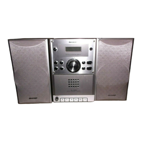
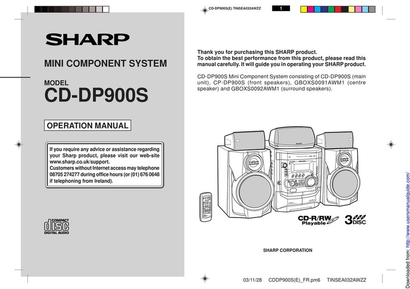
Sharp XL-40H User manual

– 1 –
XL-40H/50H
CONTENTS Page
SAFETY PRECAUTION FOR SERVICE MANUAL .......................................................................................................... 2
SPECIFICATIONS ............................................................................................................................................................ 2
NAMES OF PARTS .......................................................................................................................................................... 3
OPERATION MANUAL..................................................................................................................................................... 5
DISASSEMBLY................................................................................................................................................................. 6
REMOVING AND REINSTALLING THE MAIN PARTS.................................................................................................... 7
ADJUSTMENT.................................................................................................................................................................. 9
RDS ................................................................................................................................................................................ 10
TEST MODE ................................................................................................................................................................... 11
NOTES ON SCHEMATIC DIAGRAM ............................................................................................................................. 18
TYPE OF TRANSISTOR AND LED ................................................................................................................................ 18
WAVEFORMS OF CD CIRCUIT..................................................................................................................................... 19
BLOCK DIAGRAM .......................................................................................................................................................... 20
SCHEMATIC DIAGRAM / WIRING SIDE OF P.W.BOARD............................................................................................ 24
TROUBLESHOOTING .................................................................................................................................................... 34
FUNCTION TABLE OF IC .............................................................................................................................................. 40
LCD SEGMENT .............................................................................................................................................................. 48
PARTS GUIDE/EXPLODED VIEW
XL-40H
XL-50H
SERVICE MANUAL
SHARP CORPORATION
No. S2007XL40H///
• In the interests of user-safety the set should be restored to its original
condition and only parts identical to those specified should be used.
This document has been published to be used
for after sales service only.
The contents are subject to change without notice.
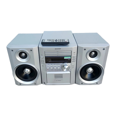
XL-40H/XL-50HMicroComponentSystemconsistingofXL-40H/XL-
50H ( main unit) and CP-XL40H/CP-XL50H (speaker system).
Illustration: XL-40H

XL-40H/50H
– 2 –
SPECIFICATIONS
FOR A COMPLETE DESCRIPTION OF THE OPERATION OF THIS UNIT, PLEASE REFER
TO THE OPERATION MANUAL.
XL-40H/50H
CP-XL40H/50H
Precaution to be taken when replacing and servicing the
Laser Pickup.
The AEL (Accessible Emission Level) of Laser Power Output
forthismodelisspecifiedtobelowerthanClassIRequirements.
However, the following precautions must be observed during
servicing to protect your eyes against exposure to the Laser
beam
(1) When the cabinet has been removed, the power is turned
on without a compact disc, and the Pickup is on a position
outerthanthelead-inposition,theLaserwilllightforseveral
seconds to detect a disc. Do not look into the Pickup Lens.
(2) The Laser Power Output of the Pickup inside the unit and
replacementservicepartshavealreadybeenadjustedprior
to shipping.
(3) No adjustment to the Laser Power should be attempted
when replacing or servicing the Pickup.
(4) Under no circumstances look directly into the Pickup Lens
at any time.
(5)CAUTION-Useofcontrolsoradjustments,orperformance
of procedures other than those specified herein may result
in hazardous radiation exposure.
SAFETY PRECAUTION FOR SERVICE MANUAL
Specifications for this model are subject to change without
prior notice.
VAROITUS! LAITTEEN KÄYTTÄMINEN MUULLA
KUIN TÄSSÄ KÄYTTÖOHJEESSA MAI NI TULLA
TAVALLA SAATTAA ALTI STAA KÄYTTÄJÄN
TURVALLI SUUSLUOKAN 1 YLITTÄVÄLLE
NÄKYMÄTTÖMÄLLE LASERSÄTEILYLLE.
VARNING - OM APPARATEN ANVÄNDS PÅ ANNAT
SÄTT ÄN I DENNA BRUKSANVI SNI NG SPECI FI
CERAS. KAN ANVÄNDAREN UTSÄTTAS FÖR
OSYNLIG LASERSTRÅLNING, SOM ÖVERSKRIDER
GRÄNSEN FÖR LASERKLASS 1.
Laser Diode Properties
Material: GaAIAs
W avelength: 780 nm
Emission Duration: continuous
Laser Output: max. 0.6 mW
CAUTION-INVISIBLE LASER RADIATION WHEN OPEN. DO NOT STARE INTO
BEAM OR VIEW DIRECTLY WITH OPTICAL INSTRUMENTS.
VARNING-OSYNLIG LASERSTRALNING NAR DENNA DEL AR OPPNAD. STIRRA
EJ IN I STRALEN OCH BETRAKTA EJ STRALEN MED OPTISKA INSTRUMENT.
ADVERSEL-USYNLIG LASERSTRALING VED ABNING. SE IKKE IND I
STRALEN-HELLER IKKE MED OPTISKE INSTRUMENTER.
VARO! AVATTAESSA OLET ALTTIINA NAKYMATON LASERSATEILYLLE.
ALA TUIJOTA SATEESEEN ALAKA KATSO SITA OPTISEN LAITTEEN LAPI.
VARNING-OSYNLIG LASERSTRALNING NAR DENNA DEL AR OPPNAD.
STIRRA EJ IN I STRALEN OCH BETRAKTA EJ STRALEN GENOM OPTISKT
INSTRUMENT.
ADVERSEL-USYNLIG LASERSTRALING NAR DEKSEL APNES. STIRR IKKE
INN I STRALEN ELLER SE DIREKTE MED OPTISKE INSTRUMENTER.
LASER KLASSE 1
LUOKAN 1 LASERLAITE
KLASS 1 LASERAPPARAT
●Cassette deck section
Frequency re- 50 - 14,000 Hz (Normal tape)
sponse:
Signal/noise ratio: 50 dB
Wow and flutter: 0.3 % (DIN 45 511)
● Speaker section
Type: Full range speaker system
Speakers: 10 cm (4") full-range speaker
Rated input
power: 5 W
Maximum input
power: 10 W
Impedance: 4 ohms
Dimensions: Width; 145 mm (5-3/4")
Height; 240 mm (9-1/2")
Depth; 191 mm (7-1/2")
Weight: 1.3 kg (2.9 lbs.)/each
●General
Power source: AC 230 V, 50 Hz
Power consumption: 26 W
Dimensions: Width; 160 mm (6-5/16")
Height; 241 mm (9-1/2")
Depth; 249 mm (9-13/16")
Weight: 2.7 kg (6.0 lbs.)
●Amplifier section
Output power: PMPO; 28 W (total)
MPO; 14 W (7 W + 7 W)
(DIN 45 324)
RMS; 10 W (5 W + 5 W)
(DIN 45 324)
Output terminals: Speakers; 4 ohms
Headphones; 16-50 ohms
(recommended; 32 ohms)
● Tuner section
Frequency range: FM; 87.5-108 MHz
AM; 522-1,620 kHz
●Compact disc player section
Type: Compact disc player
Signal readout: Non-contact, 3-beam semi-
conductor laser pickup
D/A converter: 1-bit D/A converter
Filter: 8-times oversampling digital
filter
Frequency response: 20 - 20,000 Hz
Wow and flutter: Unmeasurable
(less than 0.001% W. peak)

– 3 –
XL-40H/50H
NAMES OF PARTS
XL-40H/50H
■Front panel
1. Timer Indicator
2. Record Indicator
3. Sleep Indicator
4. (CD) Random Indicator
5. (CD/TUNER) Memory Indicator
6. RDS Indicator
7. Traffic Programme Indicator
8. Traffic Announcement Indicator
9. FM Stereo Mode Indicator
10. (CD) Play Indicator
11. (CD) Repeat Indicator
12. EON Indicator
13. Programme Type Indicator
14. Traffic Information Indicator
15. FM Stereo Indicator
16. CD Compartment
17. EON Button
18. On/Stand-by Button
19. Programme Type/Traffic Information
Search Button
20. (CD/TAPE) Stop Button
(TUNER) Memory Clear Button
21. Record Pause Button
22. Bass/Treble Selector Button
23. Memory/Set Button
24. Clock/Timer/Sleep Button
25. Band Selector Button
26. (CD) Review Button
(TAPE) Rewind Button
(TUNER) Tuning Down Button
27. Function Selector Button
28. Headphone Socket
29. CD Eject Button
30. ASPM Button
31. Remote Control Sensor
32. Display Mode Selector Button
33. Volume Select Button
34. (CD) Play/Pause Button
(TAPE) Play Button
35. Jog Dial
36. (CD) Cue Button
(TAPE) Fast Forward Button
(TUNER) Tuning Up Button
37. Volume/Jog Dial Selector Button
38. Cassette Compartment
■Rear panel
1. AC Power Input Socket
2. FM 75 ohms Aerial Socket
3. AM Loop Aerial Input Socket
4. Speaker Terminals
123 456789
11 12 13 14 15
10
16
17
18
19
20
21
22
23
24
29
30
31
32
33
34
35
36
37
38
25
26
27
28
1
2
3
4

XL-40H/50H
– 4 –
CP-XL40H/50H
XL-40H/50H
■Speaker section
1. Bass Reflex Duct
2. Full-Range Speaker
3. Speaker Wire
■Remote control
1. Remote Control Transmitter LED
●Tuner control section
2. Programme Type/Traffic Information
Search Button
3. Preset Up/Down Buttons
●CD control section
4. Clear Button
5. Random/Repeat Button
6. Memory Button
7. Stop Button
8. Play/Pause Button
9. Track Down/Review Button
10. Track Up/Cue Button
●Tape control section
11. Record Pause Button
12. Rewind Button
13. Stop Button
14. Play Button
15. Fast Forward Button
●Common section
16. Sleep Button
17. Bass Up/Down Buttons
18. Function Selector Buttons
19. On/Stand-by Button
20. Timer Button
21. Clock Button
22. Treble Up/Down Buttons
23. Volume Up/Down Buttons
1
2
3
2
4
5
6
11
12
3
7
8
9
10
13
14
15
21
23
16
17
18
19
20
22
1

– 5 –
XL-40H/50H
OPERATION MANUAL
PREPARATION FOR USE
■Connecting the AC power lead
AC 230 V, 50Hz
To an AC socket
To AC INPUT
Connect the AC power lead to the AC power input
socket, then connect theAC power lead plug to an
AC socket.
Notes:
●Unplug theAC power lead from theAC socket if
the unit is not to be used for a prolonged period
of time.
●Never use a power lead other than the one sup-
plied. Otherwise, a malfunction or an accident
may occur.
15
15
Notes concerning use:
●Replacethe batteries if the operating distance is
reduced or if the operation becomes erratic.
●Periodically clean the transmitter LED on the re-
mote control and the sensor on the main unit
with a soft cloth.
●Exposing the sensor on the main unit to strong
light may interfere with operation. Change the
lighting or the direction of the unit.
●Keep the remote control away from moisture,
excessive heat, shock, and vibrations.
0.2m - 6m
(8” - 20”)
■Remote control
RESETTING THE MICROCOMPUTER
1
33
2,3
AC INPUT
Reset the microcomputer under the following
conditions:
●Toerase all of the stored memory contents (clock
and timer settings, and tuner and CD presets).
●If the display is not correct.
●If the operation is not correct.
1
Press the ON/STAND-BY button to enter the
stand-by mode.
2
Unplug the AC power lead from the AC INPUT
socket on this unit.
3
Whilst pressing down the MEMORY/SET but-
ton and the button, plug the AC power lead
into the AC INPUT socket on this unit.
Caution:
●Theoperationexplainedabovewillerase all data
stored in memory, such as clock and timer set-
tings, and tuner and CD presets.
SETTING THE CLOCK
1
Press the CLOCK/TIMER/SLEEP button to en-
ter the time check mode.
2
Within3seconds,press the MEMORY/SETbut-
ton.
3
Turnthe jog dial to selectthetimedisplaymode.
0:00 AM 12:00
“0:00” →The 24-hour display will appear.
(0:00 - 23:59)
“AM 12:00” →The 12-hour display will appear.
(AM 12:00 - PM 11:59)
●Note that this can only be set when the unit is
first installed or it has been reset (see page 26).
4
Press the MEMORY/SET button.
5
Adjust the hour by turning the jog dial.
●When the jog dial is turned one click clockwise,
thetimewillincrease by 1 hour.Whenitis turned
one click anti-clockwise, the time will decrease
by 1 hour.
Keepturningthejogdialto change the time con-
tinuously.
●When the 12-hour display is selected, “AM” will
change automatically to “PM”.
(Main unit operation)
In this example, the clock is set for the 24-hour
(0:00) system.
CLOCK/TIMER/
SLEEP
MEMORY/SET
Jog dial
6
Press the MEMORY/SET button.
7
Adjust the minutes by turning the jog dial.
●When the jog dial is turned one click clockwise,
the time will increase by 1 minute. When it is
turned one click anti-clockwise, the time will de-
crease by 1 minute.
Keepturningthejogdialto change the time con-
tinuously.
●The hour setting will not advance even if min-
utes advance from “59” to “00”.
8
Press the MEMORY/SET button.
●Theclockstarts operating from“0”second.(Sec-
onds are not displayed.)
Note:
●In the event of a power failure or when the AC
powerleadisdisconnected,theclockdisplaywill
go out.
WhentheAC power supply is restored, the clock
display will flash on and off to indicate the time
when the power failure occurred or when the AC
power lead was disconnected.
If this happens, follow the procedure below to
change the clock time.
To change the clock time:
Perform steps 1, 2 and 4 - 8 above.
To change the time display mode:
1
Perform steps 1 - 3 in the section “RESETTING
THE MICROCOMPUTER”, on page 26.
2
Perform steps 1 - 8 above.

XL-40H/50H
– 6 –
1 Side Panel
(Left/Right)
1. Screw .................. (A1) x8 6-1
2 Top Cabinet 1. Screw .................. (B1) x1 6-1
Switch PWB 2. Socket ................. (B2) x2
3 Rear Panel 1. Screw .................. (C1) x2 6-1
4 Main PWB/ 1. Screw .................. (D1) x3 6-2
Headphones PWB 2. Screw .................. (D2) x2
3. Bracket ................ (D3) x1
4. Socket ................. (D4) x3
5. Flat wire............... (D5) x1
6. Socket ................. (D6) x1
5 Jog Switch PWB 1. Socket ................. (E1) x1 6-2
2. Screw .................. (E2) x2
3. Knob .................... (E3) x1
6 Display PWB/ 1. Screw .................. (F1) x2 6-2
LED PWB 2. Screw .................. (F2) x3
(With Jog Motor 3. Bracket ................ (F3) x1
Flame) 4. Socket ................. (F4) x1
5. Hook .................... (F5) x2
6. Hook .................... (F6) x2
7 Front Panel 1. Screw .................. (G1) x1 6-2
2. Socket ................. (G2) x1
3. Screw .................. (G3) x1
8 Power PWB 1. Screw .................. (H1) x4 6-2
2. Screw .................. (H2) x1
3. Screw .................. (H3) x1
4. Bracket ................ (H4) x1
9 Tape Mechanism 1. Open the cassette holder 6-3
2. Screw .................. (J1) x4
10 CD PWB/ 1. Screw .................. (K1) x3 6-4
Open Close Switch 2. Hook .................... (K2) x2
PWB (Note) 3. Socket ................. (K3) x3
11 CD Mechanism 1. Screw .................. (L1) x3 6-4
DISASSEMBLY
Figure 6-2
Figure 6-3
STEP REMOVAL PROCEDURE FIGURE
Figure 6-1
XL-40H/50H
XL-40H/50H
Note:
After removing the connector for the optical pickup fromthe
connectorwraptheconductivealuminiumfoilaroundthefront
end of connector so as to protect the optical pickup from
electrostatic damage.
Caution on Disassembly
Follow the below-mentioned notes when disassembling
the unit and reassembling it, to keep it safe and ensure
excellent performance:
1. Take cassette tape and compact disc out of the unit.
2. Be sure to remove the power supply plug from the wall
outlet before starting to disassemble the unit.
3.Take off nylon bandsorwire holders where theyneedto
beremovedwhendisassemblingtheunit.Afterservicing
theunit, be sure torearrange the leads wheretheywere
before disassembling.
4. Take sufficient care on static electricity of integrated
circuits and other circuits when servicing.
(A1)x2
ø3x10mm
(B2)x1
(C1)x1
ø3x10mm
Side Panel
(Right)
Front
Panel
RearPanel
(C1)x1
ø3x10mm
Side Panel
(Lift)
(B2)x1
(A1)x4
ø3x10mm
(A1)x1
ø3x10mm
(A1)x1
ø3x10mm
(B1)x1
ø3x10mm
Top Cabinet
CD PWB
Display
PWB
Main PWB
Figure 6-4
Figure 6-5
Tape
Mechanism
Open
(J1)x4
ø2.5x10mm
Front Panel
Cassette
Holder
CD Mechanism
(L1)x3
ø2.5x10mm
PWB Washer x3
Top Cabinet
(F2)x2
ø2.5x10mm
(F2)x1
ø2.5x10mm
(F1)x2
ø2.5x14mm
(E2)x2
ø2.5x12mm
(D2)x1
ø3x8mm
Main PWB
Power PWB
Power PWB Main Power Transformer
Sub Power
Transformer
Front Panel
Display PWB
LED
PWB
(H1)x4
ø3x6mm
(D2)x1
ø3x8mm
(D3)x1
(G2)x1
(H2)x1
ø3x10mm
(H3)x1
ø3x6mm (G1)x1
ø3x8mm
(G3)x1
ø3x6mm
(D4)x1
(D4)x1
(F3)x1 (D5)x1
(F5)x2
(F6)x2
(E3)x1
(D4)x1
(H4)x1
Tape
Mechanism
PWB
(F4)x1
Headphones
PWB
(E1)x1
(D1)x2
ø3x10mm
Sub Power Transformer
Jog Motor
Holder
Jog Switch
PWB
(D6)x1
(D1)x1
ø3x10mm
(K1)x3
ø2.5x14mm
(K3)x1
(K2)x2
(K3)x2
Top Cabinet
CD PWB
Open/Close
Switch PWB
CD Motor PWB CD Mechanism

– 7 –
XL-40H/50H
TAPE MECHANISM SECTION
Perform steps 1 to 7 and 9 of the disassembly method to
remove the tape mechanism. (See page 6.)
How to remove the record / playback and erase
heads (See Fig. 7-2.)
1. Remove the screws (A1) x 2 pcs., to remove the erase
head.
2. Remove the screws (A2) x 2 pcs., to remove the record/
playback head.
Note:
After replacing the heads and performing the azimuth
adjustment, be sure to apply screwlock.
How to remove the pinch roller (See Fig. 7-3.)
1. Carefully bend the pinch roller pawl in the direction of the
arrow <A>, and remove the pinch roller (B1) x 1 pc.,
upwards.
How to remove the belts (See Fig. 7-4.)
1. Remove the main belt (C1) x 1 pc., from the motor pulley.
2. Remove the FF/REW belt (C2) x 1 pc., from the REW/FF
roller.
3. Put on the belts in the reverse order of removal.
Note:
Whenputting onthebelt,ascertainthat the beltisnottwisted,
and clean it.
How to remove the motor
(See Figs. 7-5.)
1. Remove the mainbelt.
2. Remove the screws (D1) x 2 pcs., to remove the motor
bracket.
3. Remove the screws (D2) x 3 pcs., to remove the motor.
Note:
Whenmountingthemotor,payattentiontothemotormounting
angle
Figure 7-2
Figure 7-3
Figure 7-4
Figure 7-5
<A>
Pinch Roller
(B1)x1 Pinch Roller
Pawl
REMOVING AND REINSTALLING THE MAIN PARTS
Main Belt
(C1)x1
FF/REW Belt
(C2)x1
REW/FF
Clutch
Motor
1 Speaker 1. Front panel.......... (A1) x1 7-1
2. Screw .................. (A2) x4
STEP REMOVAL PROCEDURE FIGURE
CP-XL40H/50H
Figure 7-1
(A2)x4
ø4x12mm
(A1x1) Woofer
Speaker Box
Driver
Direction of handle
Driver should be
pried away from
speaker Box.
Erase Head
Record/
Playback Head
(A1)x2
ø2x8mm
(A2)x1
ø2x3mm
(A2)x1
ø2x7mm
(D1)x1
ø2x4mm
(D2)x3
Special
Screw
Motor
Bracket
Motor
Motor
(D1)x1
ø2x4mm

XL-40H/50H
– 8 –
Figure 8-4
How to remove the pickup (See Fig. 8-4)
1. Remove the mechanism cover, paying attention to the
pawls (A1) x 4 pcs.
2. Remove the screws (A2) x 2 pcs., to remove the shaft (A3)
x 1 pc.
3. Remove the stop washer (A4) x 1 pc., to remove the gear
(A5) x 1 pc.
4. Remove the pickup.
Note:
After removing the optical pickup connector wrap the front
end of connector in conductive aluminium foil so as to
prevent damage of optical pickup by static electricity.
CD MECHANISM SECTION
Perform steps 1, 2 and 10, 11 of the disassembly method to
remove the CD mechanism.
Pickup Unit
(A2) x2
ø2.6 x6mm
(A1) x2
CD Mechanism
Shaft
(A3) x1
Gear
(A5) x1
StopWasher
(A4) x1
Mechanism Cover
(A1) x2
How to remove the tape mechanism PWB
(See Fig. 8-2.)
1. Remove the screws (F1) x 1 pc., to remove the tape
mechanism PWB.
2. Remove the screws (F2) x 1 pc.
3. Remove the solder joints (F3) x 2 pcs., to remove the tape
mechanism PWB.
How to remove the jog motor
(See Figs. 8-3.)
1. Remove the side panel and top cabinet.
2. Remove the jog belt (G1) x 1 pc., from the motor pulley.
3.Removethe screws (G2) x 2pcs.,toremove the jog motor.
Note:
Whenputting onthebelt,ascertainthat the beltisnottwisted,
and clean it.
Figure 8-2
Figure 8-3
(G2)x2
ø2x5mm
Worm
Gear Jog Belt
(G1)x1 Jog Motor
Holder
Jog Motor
Display PWB
Figure 8-1
How to remove the flywheel (See Fig. 8-1.)
1. Remove the belt.
2.Removethestopwasher(E1)x1pc.,withasmallprecision
screwdriver to extract the flywheel from the capstan metal.
Note:
When the stop washer is deformed or damaged, replace it
with a new one.
How to reinstall the parts
Installeachpart in the reverse orderoftheremoval with care.
Stop
Washer Driver
(E1)x1
Stop Washer
Mechanism
Chassis
Washerx2
Flywheel
Tape
Mechanism
PWB Tape
Mechanism
PWB
(F3)x2
Solder
Joint
(F2)x1
ø2x8mm
(F1)x1
ø2x3mm

– 9 –
XL-40H/50H
MECHANISM SECTION
• Driving Force Check
Torque Meter Specified Value
Play: TW-2412 Over 80 g
• Torque Check
Torque Meter
Play: TW-2111 30 to 60 g. cm
Fast forward: TW-2231 55 to 140 g.cm
Rewind: TW-2231 55 to 140 g.cm
Specified
Value
Adjusting
Point Instrument
Connection
Test Tape
ADJUSTMENT
Specified Value
• Tape Speed
Figure 9-1 ADJUSTMENT POINT
TUNER SECTION
Figure 9-2 ADJUSTMENT POINTS
MAIN PWB
FM
ANTENNA
SOCKET
T351
R336
CNP301
AM
ANTENNA
SOCKET
FE301
VR351
FM Mute
Level
AM IF
TP301
SO301
T302
AM
Tracking fL
T306
AM Band
Coverage fL
MTT-111 Variable 3,000 ±Headphone
resistor in 90 Hz terminal
motor.(M901)
TAPE MECHANISM
M901
Tape
Motor
Variable
resistor
Adjusting
Parts
Display
Frequency
• Setting the Test Mode
Keeping the FF/FWD button and MEMORY/SET button
pressed, turn on POWER. Then, the frequency is initially set
in the memory as shown in Table. Call it with the JOG DIAL
knob to use it for adjustment and check of tuner circuit.
Preset No. FM Preset No. AM
1 87.50 MHz 6 522 kHz
2 108.00 MHz 7 1,620 kHz
3 98.00 MHz 8 990 kHz
4 90.00 MHz 9 603 kHz
5 106.00 MHz 10 1,404 kHz
• FM Mute Level
Signal generator: 1 kHz, 40 kHz dev., FM modulated
Adjust so that an output signal appears.
Check Point Instrument
Connection
Display
Frequency
87.5 MHz 87.5 MHz 2.2 V ±0.7 V TP301
108 MHz 108 MHz 7.3 V ±1.0 V TP301
• Check FM VT
Signal generator: 1 kHz, 40 kHz dev., FM modulated
98.00 MHz 98.00 MHz VR351*1 Input: SO301
(30 dBµV) Output: Speaker
Terminal
Instrument
Connection
*1. Input: Antenna, Output: Speaker Terminal
*2. Input: Input is not connected, Output: TP301
Frequency Frequency Display Setting/
Adjusting
Parts
Instrument
Connection
IF 450 kHz 1,620 kHz T351 *1
AM Band — 522 kHz (fL): T306 *2
Coverage 1.1 ±0.1 V
AM 990 kHz 990 kHz (fL): T302 *1
Tracking
fL: Low-renge frequency
fH: High-renge frequency
Signal generator: 400 Hz, 30%, AM modulated
• AM IF/RF

XL-40H/50H
– 10 –
(Continued)
LIGHT M: Classical Musical for general, rather
than specialist appreciation. Exam-
ples of music in this category are in-
strumental music, and vocal or cho-
ral works.
CLASSICS: Performances of major orchestral
works, symphonies, chamber music,
etc., and including Grand Opera.
OTHER M: Musical styles not fitting into any of
the other categories. Particularly
used for specialist music of which
Rhythm & Blues and Reggae are
examples.
WEATHER: Weather reports and forecasts and
meteorological information.
FINANCE: Stock Market reports, commerce,
trading, etc.
CHILDREN: Forprogrammes targeted at a young
audience,primarilyforentertainment
and interest, rather than where the
objective is to educate.
SOCIAL: Programmesabout people and things
that influence them individually or in
groups. Includes: sociology, history,
geography, psychology and society.
RELIGION: Any aspect of beliefs and faiths, in-
volving a God or Gods, the nature of
existence and ethics.
PHONE IN: Involving members of the public ex-
pressing their views either by phone
or at a public forum.
TRAVEL: Features and programmes con-
cerned with travel to near and far
destinations, package tours and
travelideas and opportunities. Not for
use for announcements about prob-
lems,delays,orroad-worksaffecting
immediatetravel where TP/TAshould
be used.
LEISURE: Programmesconcernedwithrecrea-
tional activities in which the listener
might participate. Examples include,
Gardening, Fishing, Antique collect-
ing, Cooking, Food & Wine, etc.
JAZZ: Polyphonic,syncopatedmusicchar-
acterised by improvisation.
COUNTRY: Songs which originate from, or con-
tinue the musical tradition of the
American Southern States. Charac-
terised by a straightforward melody
and narrative story line.
NATION M: Current Popular Music of the Nation
or Region in that country’s language,
as opposed to international ‘Pop’
which is usually US or UK inspired
and in English.
OLDIES: Musicfrom the so-called “goldenage”
of popular music.
FOLK M: Music which has its roots in the mu-
sical culture of a particular nation,
usually played on acoustic instru-
ments. The narrative or story may be
basedon historical events or the peo-
ple.
DOCUMENT:
Programme concerned with factual
matters,presented in an investigative
style.
TEST: Broadcast when testing emergency
broadcast equipment or receivers.
ALARM: Emergencyannouncement made un-
derexceptional circumstances to give
warning of events causing danger of
a general nature.
NONE: No programme type (receive only).
TP: Broadcasts which carry traffic an-
nouncements.
TA: Traffic announcements are being
broadcast at present.
Note:
●When the unit is in the EON stand-by mode and
aprogrammeisselected, the unit will display “TI”
instead of “TP” or “TA”.
3
4
2
7
15 6
11
10
14
15
12
13
16
98
Vdda
Vssa
MPXIN
TEST TEST
CLK(4.332MHz)
OSC
XIN XOUT
RDS-ID/
READY
RST
MODE
RDCL
RDDA
Vssd
Vddd
PLL
(57kHz)
CLOCK
RECOVERY
(1187.5Hz)
DATA
DECODER
RAM
(128-bits)
RDS-ID
DETECT
REFERENCE
VOLTAGE
ANTIALISING
FILTER
57kHz
BPF
(SCF)
SMOOTHING
FILTER
VREF
VREF FLOUT CIN
IC521 VHiLC72723M-1: RDS Circuit (LC72723M)
1 VREF Reference voltage output (Vdda/2).
2 MPXIN Baseband (multiplexed) signal input.
3 Vdda Analog power supply (+5V).
4 Vssa Analog ground.
5 FLOUT Subcarrier output (filter output).
6 CIN Subcarrier input (comparator input).
7 TEST Test input.
8 XOUT Crystal oscillator output (4.332MHz).
9 XIN Crystal oscillator input (external reference signal input).
10 Vssd Digital ground.
11* Vddd Digital power supply (+5V).
12 MODE Read mode setting (0 : master, 1: slave).
13 RST RDS-ID/RAM reset (positive polarity).
14 RDDA RDS data output.
15* RDCL RDS clock output (master mode)/ RDS clock input (slave mode).
16* RDS-ID/ RDS-ID/READY output (negative polarity).
READY
Pin
No. Port
Name Function
RDS
In this unit, the terminal with asterisk mark (*) is (open) terminal which is not
connected to the outside.
RDS (Radio Data System) OPERATION
RDS is a broadcasting service which a growing
number of FM stations are now providing. It allows
these FM stations to send additional signals along
with their regular programme signals. For exam-
ple, the stations send their station names, and in-
formation about what type of programme they
broadcast, such as sports or music, etc.
When tuned to an FM station providing the RDS
service,RDSwillappear,the station frequency (and
then the station name if sent) will be displayed.
The TP (Traffic Programme) will appear on the dis-
playwhenthe received broadcast carries traffican-
nouncements, and the TA (TrafficAnnouncement)
will appear whilst a traffic announcement is being
received.
EON will appear whilst the EON (Enhanced Other
Networks information) data is being broadcast.
Note:
When the TP and TA appear at the same time, an
announcement is being made.
When only the TA appears, an announcement is
not being made.
■Information Provided by RDS
WiththeXL-40H/XL-50H, you can display two types
of RDS service. To show them in the display, press
the DISPLAY MODE button.
Each time you press the DISPLAY MODE button,
the display will change to show the following in-
formation.
Station names commonly
known will be displayed.
"NO PS" appears if no
signal is being received.
Programme type will be
displayed.
"NO PTY" appears if no
signal is being received.
Station frequencies.
PS
(Programme Service):
PTY
(Programme Type):
Station Frequency:
Descriptions of the PTY (Programme Type)
codes, TP (Traffic Programme) and TA (Traffic
Announcement)
With the XL-40H/XL-50H, you can search for and
receive the following PTY, TP and TA signals.
NEWS: Short accounts of facts, events and
publicly expressed views, reportage
and actuality.
AFFAIRS: Topicalprogrammeexpandingor en-
larging upon the news, generally in
different presentation style or con-
cept, including debate, or analysis.
INFO: Programmeswhosepurposeistoim-
part advice in the widest sense.
SPORT: Programme concerned with any as-
pect of sport.
EDUCATE: Programme intended primarily to
educate,of which the formal element
is fundamental.
DRAMA: All radio plays and serials.
CULTURE: Programmes concerned with any as-
pect of national or regional culture,
including language, theatre, etc.
SCIENCE: Programmes about the natural sci-
ences and technology.
VARIED: Used for mainly speech-based pro-
grammes usually of light-entertain-
ment nature, not covered by other
categories. Examples include: quiz-
zes, panel games, personality inter-
views.
POP M: Commercialmusic,which would gen-
erally be considered to be of current
popularappeal,oftenfeaturing in cur-
rent or recent record sales charts.
ROCK M: Contemporarymodernmusic,usually
written and performed by young mu-
sicians.
EASY M: Current contemporary music consid-
ered to be “easy-listening”, as op-
posed to Pop, Rock or Classical, or
one of the specialised music styles,
Jazz, Folk or Country. Music in this
category is often but not always, vo-
cal, and usually of short duration.
DISPLAY
MODE
– 11 –
XL-40H/50H
2. CD Test Mode (TEST 1)
In the CD test mode the operation of each step is enabled even when the LID-SW is off. However, if focus cannot be set in step
3 or any error processing is started, it is impossible to proceed to the next step. When the error processing is started, operations
otherthanterminationoftestmodebypressingthePOWERbuttonorreturntothestep1bypressingtheSTOPbuttonareinhibited.
1. Step 1 Mode
When the CD test mode is turned on, the following indication lights, the processing (until turning-off of CD STB terminal of CD
initialization operation flow) is executed, and the next button input is waited.
After lighting for one second
If the following operation buttons are pressed in this state, the operation is performed as follows.
"POWER".................The test mode is turned off, the power is turned off, and the ordinary standby mode is set.
"FF/FWD".................After the pickup returns once to the innermost periphery, it slides toward the outer periphery while this
button is held down.
"REW/REV"..............After the pickup returns once to the innermost periphery, it slides toward the inner periphery while this
button is pressed. However, if PU-IN is on, input is invalid.
"PLAY" .....................Shift to step 2
"STOP".....................Invalid
"REC PAUSE"..........Shift to step 5
* In case of initialization the pickup is moved toward the inner periphery. Any buttons other than "POWER" button are not
accepted until the shift of pickup to the inner periphery is completed at this time. If PU-IN SW ON cannot be detected within
10 seconds, the slide motor is stopped, and the following error indication appears. Press the POWER button to end the test
mode, or press the STOP button to return to step 1. Any other operations are inhibited.
TEST MODE
The test mode applied to this microcomputer has three modes, namely ordinary test mode to be used for adjustment or
measurement, aging test mode to be used for aging test, and self-diagnosis test mode for self-inspection in case of final product
inspection.
The test mode specification prescribes the microcomputer with RDS (RH-IX0026SJZZ) . There are two types of indication
examples; large ones for the microcomputer with RDS, and smaller ones for the microcomputer without RDS.
1. Turning on the test mode
To turn on the specific test mode, press the POWER button, holding down the following two buttons in the ordinary stand-by
mode (power off state). In this case only the main unit button is valid. Even when the POWER of remote control button is set
to on, the test mode is not turned on.
[Ordinary test mode]
1. CD Test Mode (TEST 1)…………………… Volume/JOG Dial Selector + FF/FWD
2. Tuner Test Mode (TEST 2)………………… Volume/JOG Dial Selector + Volume Select
3. Electronic volume Test Mode (TEST 3)……REW/REV + FF/FWD
4. Timer Test Mode (TEST 4)………………… FUNCTION + Volume Select
5. LCD Test Mode (TEST 5)……………………FUNCTION + FF/FWD
REW/REV + Volume Select
[Self-diagnosis Test Mode]
1. Button input diagnosis test mode (TEST6).…

XL-40H/50H
– 12 –
The time display indicates always "0:00".
When the following buttons are pressed in this state, the operation is executed as follows.
"POWER" ................The test mode is turned off, the power is turned off, and the ordinary standby mode is set.
"FF/FWD" ................The pickup slides toward the outer periphery while this button is held down.
"REW/REV" .............The pickupslides towardthe innerperiphery whilethis button isheld down.However, ifPU-IN ison, input
is invalid.
"PLAY".....................Shift to step 5
"STOP" ....................Return to step 1
"REC PAUSE" .........Shift to step 5
*If the focus is disturbed, the process returns to step 1.
4. Step 4 Mode
TheCLVservo ON command (8600) sending operation is performed, and the next button input is waited. (The disc is rotated
to perform CLV locking.)
When the following operation buttons are pressed in this state, the operation is executed as follows.
"POWER" ................The test mode is turned off, the power is turned off, and the ordinary standby mode is set.
"FF/FWD" ................The pickup slides toward the outer periphery while this button is held down.
"REW/REV" .............The pickupslides towardthe innerperiphery whilethis button isheld down.However, ifPU-IN ison, input
is invalid.
"PLAY".....................Ifthe focushas been set, shifttostep 4 is executed.Ifthe focus has notbeenset, acceptance isinhibited.
"STOP" ....................Return to step 1
"REC PAUSE" .........Shift to step 5
*If the focus is disturbed after it has been set, the process returns to step 1.
3. Step 3 Mode
The laser is kept lighting. The processing (until turning-on of CLV servo of CD initialization operation flow) is executed, and
the next button input is waited. (The focus servo is turned on, and focus search is performed.)
The focus search is repeated until the focus is set.
If the following buttons are pressed in this state, the operation is performed as follows.
"POWER" ................The test mode is turned off, the power is turned off, and the ordinary standby mode is set.
"FF/FWD" ................The pickup slides toward the outer periphery while this button is held down.
"REW/REV" .............The pickup slidestoward the innerperiphery while thisbutton is helddown. However, ifPU-IN is on,input
is invalid.
"PLAY".....................Shift to step 3
"STOP" ....................Return to step 1
"REC PAUSE" .........Shift to step 5
2. Step 2 Mode
When the "PLAY" button is pressed in this mode, the laser lighting command LDON (8400) is sent, and the laser is turned on.
Other operations are not performed.

– 13 –
XL-40H/50H
3. Tuner Test Mode (TEST 2)
1. Outline of tuner (radio) test mode
The tuner test mode is intended to store the adjustment and measurement frequencies in the preset memory CH without
frequency setting by adjusting personnel when the tuner section is adjusted in the production line.
2. Details of tuner test mode
When the power is turned on by using the "POWER" button while the "Volume/JOG Dial Selector" and "Volume Select"
buttonsare held down inPOWEROFF state, the frequencyforadjustment and measurement ofdestinationspecified by the
AREAterminal is preset andstoredinthepresetmemory CH. However, Ordinary 1andOrdinary2areset to the designation
(destinationselectedbySPANswitchingoperation)setwhenthetestmodeisset.(Asforfrequenciestobepresetandstored
for each destination, refer to item 3.)
The tuner test mode is started from preset No.1.
The operations of test mode are identical with the ordinary operations of TUNER function. However, FUNCTION switching
is invalid.
Since it is necessary to discard the content of preset memory when the tuner test mode is ended, "0000" or "1111" bits are
writteninthememorytobecheckedincaseofmemorycheck(incaseofinitialsetting)sothatmemoryabnormalityisdetected
in case of initial setting so as to ensure memory initialization.
When the tuner test mode is turned on, the following indication lights for one second.
• The TUNER TEST2 mode is set as a result of Volume Select + POWER. -> IF AC is set to OFF in the TEST2 mode, the initial
state is restored.
When POWER is set to OFF, the memory of TEST2 mode is protected.
When the power is turned on again, the ordinary operation is enabled while the data is stored in the
memory (besides TUNER).
If AC OFF state is maintained in this state for about 1/2 day, start is executed in the initial state.
• To clear the whole memory, insert the AC cord, holding down MEMORY + PLAY.
When the following operation buttons are pressed in this sate, the operation is executed as follows.
"POWER".................The test mode is turned off, the power is turned off, and the ordinary standby mode is set.
"FF/FWD".................The pickup slides toward the outer periphery while this button is held down.
"REW/REV"..............The pickupslides toward the innerperipherywhile this buttonisheld down. However, ifPU-IN is on, input
is invalid.
"PLAY" .....................Invalid
"STOP".....................Return to step 1
"FUNCTION"............Shift to step 6
"BAND" ....................Shift to step 7
*If the focus is disturbed, the process returns to step 1.
Other cautions
• TOC IL is not executed in the test mode.
• As for button operations other than those shown above, only the sound volume operation (with JOG) is accepted.
5. Step 5 Mode
The CD initialization operation flow is executed to the end, the mute is set to off, and playback is started. Even when the
playback reaches the outermost periphery of disc, the operation does not stop. The LCD display indicates the playback past
time as in case of ordinary CD playback.

XL-40H/50H
– 14 –
4. ASPM TEST Mode
When the ASPM button is pressed, the test mode is set. It starts up at FM 106.50 MHz. (ST mode)
Data of 27 CH of 04 to 30 CH are all stored at FM 87.50 MHz (ST).
01 to 03CH are kept empty (If data of 3 CH are stored, max. 30 CH is filled.)
When the ASPM button is operated in the TEST mode 3, the preset data is cleared (overwrite).
A) Operation with ASPM button
Press the "ASPM" button or hold it down. (Any button other than ASPM button cancels the ASPM test mode.)
FM 105.00 MHz (ST) is indicated, and scan is started.
(Start from 105.00 MHz)
During scanning the frequency is indicated.
End at FM 108.00 MHz (ST)
Onlythe number of presetandstored stations (number ofCHs:max. 3 stations) isindicatedfor one second inthe ASPM test
mode. When two stations are stored, "_2 MEMORY" is indicated (lighted)for one second.
("02 MEMORY" indication is not given.)
"END" is not indicated
01CH indication (for one second)
Frequency indication (for one second)
02CH indication (for one second)
Frequency indication (for one second)
03CH indication (for one second)
Frequency indication (for one second)
After indication of continuous time series for one second the indication of FM 106.50 MHz (ST) is restored.
(The preset button is not pressed. The time series is indicated automatically, and the content of memory is indicated.)
* PS name is not indicated (while the content of memory is checked)
* If only 1 CH data is stored, FM P-01 -> FM 106.00 MHz -> FM 106.50 MHz (ST)
(An example) (1 sec) (1 sec) (ST) End indication
When the ASPM button is pressed once in the TUNER TEST
mode, the indication FM 106.50 MHz (ST) appears, and data
of04to30CHare storedat87.50MHz(ST). WhentheASPM
button is operated again, the ASPM test operation mode is
set.
Incaseof"_0MEMORY"theprocessends,andthe
FM 106.50 MHz (ST) state is resumed.
Confirmation of content of memory
(Examples of concrete indication)
(An example)
FM P-01
FM 105.50MHz(ST)
FM P-02
FM 106.50MHz(ST)
FM P-03
FM 107.50MHz(ST)
Not in zero-memory state
3. Preset frequencies for various destinations (random preset memory)
• The hatched sections of the table are not stored in memory.
BAND
16-25
26 FM106.00 MHz
27 FM 90.00 MHz
28 FM FM 98.00 MHz
29 MONO FM108.00 MHz
30 FM 87.50 MHz
Europe 2, 4
CH
BAND
1 FM 87.50 MHz
2 FM108.00 MHz
3 FM FM 98.00 MHz
4 STEREO FM 90.00 MHz
5 FM106.00 MHz
Europe 2, 4
CH BAND
6 AM 522 kHz
7 AM1620 kHz
8 AM AM 990 kHz
9 AM 603 kHz
10 AM1404 kHz
11-15 LW
Europe 2, 4CH

– 15 –
XL-40H/50H
B) Cautions concerning the ASPM test mode
a) Cancel: When the "ASPM" button is pressed again during operation after it was first pressed in the test mode, the ASPM
test mode is canceled (interrupted), and the initial state FM 106.50 MHz (ST) indication is restored.
(To check the data which was preset and stored until interruption, use the preset UP/DOWN button. (JOG UP/DOWN is
also available after JOG mode button operation.)
wing indication appears.
b) The ASPM test mode is started in FM stereo state (FM 106.50 MHz ST). If any button other than ASPM button is pressed
even only once after it is started, it becomes invalid, and the ASPM test mode becomes inoperable.
Invalid: The Ordinary mode is set while 4 to 30CH data remain in memory (or 1 to 30 CH MAX data remain in memory).
The "ASPM" button can be repeatedly operated until 01CH to 03CH is filled (up to 3 stations in memory).
The number of stored stations -> Channel No. -> Frequency -> FM 106.50 MHz (ST) is indicated.
(1 second) (1 second) (1 second) (Initial state)
c) Broadcast (without PI code) which is not RDS is not preset and stored in memory.
When the ASPM mode is set, the "MEMORY/SET" button cannot be operated (the test mode is canceled).
Operation is possible after ASPM test mode operation.
d) Scan frequency: 105.00 MHz -> 108.00 MHz
Data are stored in memory so that the PI code is not duplicated (by seeing the PI code and VSM (S meter value). When
the PI code is duplicated, both VSM (S meter value) are compared. The greater one is stored in memory but the smaller
one is discarded.
For the stations having the same PI code, only one station having the highest electric field intensity is stored, and the
memory is refilled. The channels which can be preset in the ASPM test mode are 01 to 03CH. If 3 stations are stored, 30
CH are filled.
For the stations having the same electric field intensity, the former (preceding station) is stored.
e) Signal of already stored same frequency is not stored. (The previously stored data is kept.)
f) The order of preset memory is 01CH -> 02CH -> 03CH.
Up to 3 stations (1 to 3CH) can be indicated. This indication is
givenonlyintheASPMtestmode.Inothermode(notinASPM
test mode) the number of stored stations -> END is indicated
* When the "PRESET UP" button or "PRESET DOWN" button is pressed after completion, the following indication appears.
* If signal exists at 106.50 MHz, the following indication appears.
In case of memory storage with ASPM, for example, if RDS station 107.50 MHz has the PI code (the same as that of RDS
station 105.50 MHz) and VSM is greater than 105.50 MHz (PR-01), data is overwritten on 105.5 MHz which is contained in
"PR-01". (Frequency is changed to 107.50 MHz.)
If VSM is equal, previously stored 105.50 MHz remains.
WhenRDSstationisstoredinthetestmode,the2-secondblinkingofpresetNo.isnotperformedsoastosavetheproduction
line test time. ("RDS" lighting is performed.)
Note: RDS operation is performed in FM MONO state. However, in case of ASPM, ASPM scan is performed after BAND is
changed from FM MONO to FM STEREO.
Note: When the (PLAY) button is pressed in TEST 2 mode, it is possible to check the sate of IF count. However, this
function is for designer. It is not necessary for other sections.
CH indication
(for 2 seconds) Frequency indication
(for 2 seconds) Time series indication of PS name indication is enabled.
(The same as in case of Ordinary)
NO PS
(Blinking for 5 seconds: 1 Hz)Note: If PS is fixed after the frequency indication is
resumed, the PS name indication is restored.
FM 106.50 MHz When the PS data is given in case of NO PS indication, the
PS name indication is restored.
PS name
Note: If PS is fixed after the frequency indication is
resumed, the PS name indication is restored.
NO PS
(Blinking for 5 seconds: 1 Hz)

XL-40H/50H
– 16 –
4. Electronic volume Test Mode (TEST 3)
When the test mode is set, the following indication lights for one second.
When this mode is set, BASS/TREBLE is set to 0 (0 dB) and SURROUND mode is set to off, and start-up function is set to CD
whenvolumeis-14dB(STEP17).Thebuttonoperationsinthetestmodearethesameasthoseofordinaryoperationexcepting
sound volume UP/DOWN.
(1) The indication is the same as that of ordinary operation excepting test mode setting.
(2) The sound volume control with the sound volume UP/DOWN button is only the following 3 steps unlike the ordinary state.
Volume- ∞(STEP 0) <-> Volume-14 dB (STEP 23) <-> Volume-0 (STEP 30)
(3) BASS/TREBLE and SURROUND are switched when button operation is performed.
The current time and timer time are set in the following procedure to perform the timer playback.
1.Setthecurrenttimeto1:00,setthetimertoONtime1:02,setthefunctiontoTape,andsetvolumeSTEP8.Oneminuteiscounted
as one second, and the timer playback operation is performed. The fade-in (when playback is started) is executed at a rate of
one step for 0.5 sec. After completion of fade-in the fade-out is executed at a rate of one step for 0.5 sec (WAIT 1 sec inserted).
After completion of fade-out the power is turned off (after WAIT 1 sec), and the mode is changed to the standby mode.
The indication during operation is the same as that of ordinary timer operation.
5. Timer test Mode (TEST 4)
When the test mode is set, the following indication lights for one second.
g) When 01 to 03CH were all used, scan is aborted at the frequency at which filling occurred, and the following indication
appears.
Number of stored stations -> Indication of stored channel -> Indication of frequency -> Return to initial FM 106.50 MHz (ST)
(1 second) (1 second) (1 second)
h) If even one station could not be preset and stored in the APMS mode, "_0MEMORY" is indicated after scanning, and then
FM 106.50 MHz (ST) indication is restored. (The first digit is space.)
("_0MEMORY" is indicated in the test mode.)
i) When the "ASPM" button is pressed after three stations are stored (after full-memory of 30 stations), "ASPM" blinks for 2
seconds, and then FM 106.50 MHz (ST) indication is restored without ASPM scanning. (RDS automatic lighting)
(In case of ASPM button operation in full memory state)
j) After completion of specific operation FM 106.50 MHz (ST) indication is restored.
k) Test mode
Use of only the function button is inhibited.
l) The first channel to be called (when data is stored in the ASPM mode) is 01CH.
m) After start-up in the ASPM test mode the ASPM key is valid even when it is pressed many times. The test mode is kept.
If three stations are stored (1 to 3CH), full-memory state occurs.
If the ASPM button is pressed after occurrence of full-memory state, the same operation as that described in item i) is
performed.
In this period up to 3 stations are continuously indicated (1 to 3 CH).

– 17 –
XL-40H/50H
This test mode is intended to check whether all the main unit buttons can be detected. Accordingly, in this test mode checking
as to whether the "POWER" button was pressed after all the buttons shown below were pressed is performed. If the result is
OK,OKisindicated. Even any one ofkeyswasnotpressed, an error is indicated.IncaseofOK termination or error termination
exit from this mode occurs when the "POWER" button is pressed next time, and the standby mode is set.
1. In case of XL-40H/50H
The following 15 buttons are detected as all buttons.
PLAY, JOG MODE, BAND, BASS/TREBLE, FUNCTION, MEMORY/SET, REC PAUSE, REW, FF, STOP, CLOCK/TIMER/
SLEEP,PTY-TI, EON, APMS, DISPLAY
The OK/NG indication of test result is as follows.
7. Key input diagnosis Test Mode (TEST 6)
When the test mode is set, the following indication appears.
6. LCD Test Mode (TEST 5)
When the LCD test mode is set, all the LCD segments are lighted. After that the indication is changed as follows according to
the "PLAY" button input.
Lighting of all segments Lighting of odd segments Lighting of even segments

XL-40H/50H
– 18 –
NSW801 PICKUP IN ON—OFF
SW700 JOG ON—OFF
SW709 ON/STAND-BY ON—OFF
SW710 CLOCK/TIMER/SLEEP ON—OFF
SW711 TUNING UP ON—OFF
SW712 PLAY/CD PAUSE ON—OFF
SW713 VOLUME SELECT ON—OFF
SW714 DISPLAY MODE ON—OFF
SW715 ASPM ON—OFF
SW716 EON ON—OFF
SW717 PTY. TI ON—OFF
•The indicated voltage in each section is the one measured
by Digital Multimeter between such a section and the chas-
sis with no signal given.
1. In the tuner section,
( ) indicates AM
< > indicates FM stereo
2. In the main section, a tape is being played back.
3. In the deck section, a tape is being played back.
( ) indicates the record state.
4. In the power section, a tape is being played back.
5. In the CD section, the CD is stopped.
•Parts marked with “ ” ( ) are important for
maintaining the safety of the set. Be sure to replace these
parts with specified ones for maintaining the safety and
performance of the set.
NOTES ON SCHEMATIC DIAGRAM
•Resistor:
To differentiate the units of resistors, such symbol as K and
M are used: the symbol K means 1000 ohm and the symbol
M means 1000 kohm and the resistor without any symbol is
ohm-type resistor. Besides, the one with “Fusible” is a fuse
type.
•Capacitor:
To indicate the unit of capacitor, a symbol P is used: this
symbol P means micro-micro-farad and the unit of the
capacitor without such a symbol is microfarad. As to
electrolyticcapacitor,theexpression“capacitance/withstand
voltage” is used.
(CH), (TH), (RH), (UJ): Temperature compensation
(ML): Mylar type
(P.P.): Polypropylene type
•Schematic diagram and Wiring Side of P.W.Board for this
model are subject to change for improvement without prior
notice.
REF. NO DESCRIPTION POSITION POSITIONREF. NO DESCRIPTION
Figure 18 TYPES OF TRANSISTOR AND LED
SW721 MEMORY/SET ON—OFF
SW722 BASS/TREBLE ON—OFF
SW723 BAND ON—OFF
SW724 REC. PAUSE ON—OFF
SW725 STOP/CLEAR ON—OFF
SW726 TUNING DOWN ON—OFF
SW727 FUNCTION ON—OFF
SW728 VOLUME JOG ON—OFF
SW801 OPEN/CLOSE ON—OFF
SW901 FOOL PROOF ON—OFF
SW902 CAM ON—OFF
ECB
(1) (2) (3)
FRONT
VIEW
FRONT
VIEW
BCE
FRONT
VIEW
2SB562 C
2SC2001 K
2SC380 O
2SD468 C
KRA102 M
KRC102 M
KRC104 M
KRC107 M
KTA1266 GR
KTC3199 GR 2SD2012 Y MPG3372X
HY2043 SVC348S
1 2 3

– 19 –
XL-40H/50H
WAVEFORMS OF CD CIRCUIT
NO DISC FOCUS SEARCH STOP PLAY
FOO 1 TMAX 1
IC802 48pin
FO+ 2 SBOK 2
IC804 26pin IC802 12pin
FO- 3 DMO 3
IC804 25pin IC802 55pin
FOCUS SEARCH TOC IL STOP PLAY
SEL 1 TEI 1
IC802 57pin
FEI 2 TRO 2
IC802 43pin IC802 49pin
TEI 3 FMO 3
IC802 46pin IC802 53pin
STOP PLAY CUE
FEI 1 TEI 1
IC802 43pin
SBAD 2 TRO 2
IC802 44pin IC802 49pin
RFO 3 FMO 3
IC801 22pin IC802 53pin
STOP PLAY REVIEW
FEI 1 TEI 1
IC802 43pin
RFGO 2 TRO 2
IC801 19pin IC802 49pin
RFRP 3 FMO 3
IC801 17pin IC802 53pin
STOP PLAY TCD-782 TNO-02 PLAYBACK
TEI 1LO 1
IC802 46pin
TRO 2
IC802 49pin
RO 2
SBAD 3
IC802 44pin
1
2
3
4
6
7
11
15
16
17
IC802 85pin
IC802 46pin
IC802 46pin
IC802 46pin
IC802 30pin
5
6
5
7
8
5
9
10
6
11
12
13
14
6
11
15
6
11
15
IC802 82pin

XL-40H/50H
– 20 –
Figure 20 BLOCK DIAGRAM (1/4)
REC MUTE
Q105
Q106 REC
150K
150K
MUTE ALC
+
-
-
+
3 1
5
11 12
8
10
2
IC102
BA3311L
6 7
9
NF
L-IN
R-IN
NF
L-OUT
ALC
R-OUT
Q151 Q152
L151
Q153
Q171
Q172 REC
SWITCHING
Q101-Q104
SWITCHING
1
IC101
IC101
HEAD SELECTOR
BA3126N
2
3
4
5
6
9
REC SW
P/B SW
CONT
P/B SW
REC SW
8
7
A-12V
L-CH
R-CH
R-CH
L-CH
L-CH
L-CH
A-GND
A-GND
A-GND
R-CH
R-CH
ERASE
CNP101
CNS101
CNS901
P.F
CAM SW
Q906
BIAS
REC
RUN_PLS
MOT
SOL
U_CON 5V
D-GND
M_12V
1
2
3
4
5
6
7
CNP901
PH901
PHOTE INTERRUPTER
SW901
FOOL
PROOF
SW902
CAM
1
CFW901
2
+
-
2
1
M
M901
TAPE MOTOR
SOLENOID
SOL901
TO DISPLAY PWB
Q904
Q902
A_12V
A_12V
SWITCHING
B-CAN(NC)
1 2 3 4 5678
9
CNP703
M_GND
Q903
Q905
Q901
CF352 CF351
FM IF
24 22 21 20 19 18 17 16 15 14 13
12
11
10
9
8
7
6
5
4321
IC303
LA1832
22 21 20 19 18 17 16 15 14 13 12
1 2 3 4 5 6 7 8 9 10 11
IC302
LC72131
X352
X351
456kHz
X IN
NC
CE
DI
CL
MO/ST
FM
FM
DO
FM IN
X OUT
VSS
AOUT
AIN
PD
VDD
AM IN
NC
IF IN
IF REQ
SW
VCC
AM ANT
AM OSC.
VD301-1
SVC348S
VD301-2
SVC348S
VR351
10K(B)
FM MUTE LEVEL
23
T351
+5V
AM IF
VT
MUTE
R-MUTE
MO/ST
L-CH OUT
R-CH OUT
MPX VCO
AM LOW CUT
FM/AM OUT
MPX IN
AM OSC OUT
FM AFC
AM RF IN
VSM
AM OSC INAM MIX OUT
AM IF IN
GND
REG
FM IF IN
SD
STEREO
FM DET
PHASE
(AM/FM)
IF OUT
PHASE
FM IF DET./FM MPX./AM IF
4.5MHz
Q351
SWITCHING
R_MUTE
PLL CONTROLLER
ZD351
MTZJ5.1B
Q360
FM RIPPLE
FM+B A_12V
FILTER
8 7 6 4
3 1
2 5
3
1
1 3
IF OUT
F OUT
GND
GND
ANT.
VT
VT
GND
VCC
FM+B
FM IF
FM IF
Q301
CF302
FM IF
CF301
FM
ANTENNA
TERMINAL
FE301
FM FRONT END
SO301
VT
1 L341
BALUN
2
1
2
AM LOOP
ANTENNA CNP301
AM OSC OUT
AM MIX OUT
A_GND
+5V A_12V
D_GND
REC BIAS
CONT
SWITCHING
SWITCHING
RUN PLS
SOL
M_12V
U_CON5V
MOT
SWITCHING
SWITCHING
SWITCHING
TAPE MOTOR
DRIVER
SOLENOID
DRIVER
BIAS OSC
SWITCHING
AM IF IN
1
2
3
4
5
6
7
8
1
2
3
4
5
6
7
1
2
3
4
5
6
7
8
L-CH
R-CH
ERASE
HEAD
RECORD/
PLAYBACK
HEAD
T302
T306
1
2
3
IC102
REC./P.B.
EQUALIZER
AMP.
2
This manual suits for next models
1
Table of contents
Other Sharp Stereo System manuals

Sharp
Sharp CD-MPX100E User manual

Sharp
Sharp MD X5 User manual

Sharp
Sharp CD-DK890N User manual

Sharp
Sharp GF-575Z User manual

Sharp
Sharp VZ-1600H(S) User manual

Sharp
Sharp CD-BA3000 User manual

Sharp
Sharp CD-DD4500 User manual

Sharp
Sharp GX-CH170X User manual

Sharp
Sharp XL-UR5H User manual

Sharp
Sharp CD-BA200 User manual

Sharp
Sharp CD-ES770 User manual

Sharp
Sharp CD-C831W User manual

Sharp
Sharp SD-EX100H User manual

Sharp
Sharp XL-HP888H User manual

Sharp
Sharp CD-XP700H User manual

Sharp
Sharp CD-XP120W User manual

Sharp
Sharp CD-BH20 User manual

Sharp
Sharp XL-MP35H User manual

Sharp
Sharp CD-G10000P User manual

Sharp
Sharp CD-BP90W User manual