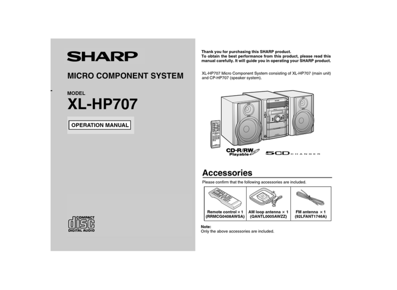
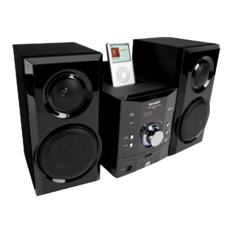
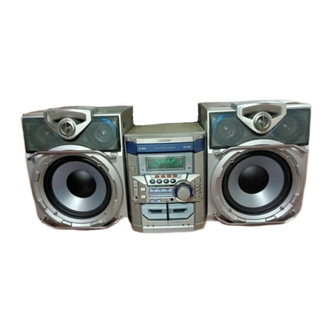
Sharp CD-CH1000 User manual

CD-CH1000
CONTENTS Page
IMPORTANT SERVICE NOTES (FOR U.S.A. ONLY)...................................................................................................... 2
SPECIFICATIONS ............................................................................................................................................................ 2
NAMES OF PARTS .......................................................................................................................................................... 3
OPERATION MANUAL..................................................................................................................................................... 5
DISASSEMBLY................................................................................................................................................................. 8
REMOVING AND REINSTALLING THE MAIN PARTS.................................................................................................. 11
CD CHANGER MECHANISM MAIN BASE PARTS ASSEMBLING/ADJUSTING PROCEDURE ................................. 13
ADJUSTMENT................................................................................................................................................................ 20
TEST MODE ................................................................................................................................................................... 21
ERROR MESSAGE LIST................................................................................................................................................ 24
NOTES ON SCHEMATIC DIAGRAM ............................................................................................................................. 25
TYPES OF TRANSISTOR AND LED.............................................................................................................................. 25
BLOCK DIAGRAM .......................................................................................................................................................... 26
SCHEMATIC DIAGRAM ................................................................................................................................................. 32
WIRING SIDE OF P.W.BOARD...................................................................................................................................... 43
WAVEFORMS OF CD CIRCUIT..................................................................................................................................... 52
TROUBLESHOOTING .................................................................................................................................................... 53
FUNCTION TABLE OF IC .............................................................................................................................................. 55
LCD DISPLAY................................................................................................................................................................. 62
PARTS GUIDE/EXPLODED VIEW
PACKING OF THE SET (FOR U.S.A. ONLY)
SERVICE MANUAL
SHARP CORPORATION
No. S8070CDCH1000
• In the interests of user-safety the set should be restored to its original
condition and only parts identical to those specified should be used.
This document has been published to be used
for after sales service only.
The contents are subject to change without notice.
CD-CH1000
CD-CH1000 Audio Tower System consisting of CD-CH1000 (main
unit) and CP-RW5000 (speaker system).
MODEL
AUDIO TOWER SYSTEM

CD-CH1000
– 2 –
IMPORTANT SERVICE NOTES (FOR U.S.A. ONLY)
BEFORE RETURNING THE AUDIO PRODUCT
(Fire & Shock Hazard)
Before returning the audio product to the user, perform the
following safety checks.
1. Inspect all lead dress to make certain that leads are not
pinchedorthathardwareisnotlodgedbetweenthechassis
and other metal parts in the audio product.
2. Inspect all protective devices such as insulating materials,
cabinet,terminalboard,adjustmentandcompartmentcovers
or shields, mechanical insulators etc.
3. To be sure that no shock hazard exists, check for leakage
current in the following manner.
* Plug the AC line cord directly into a 120 volt AC outlet.
* Using two clip leads, connect a 1.5k ohm, 10 watt resistor
paralleled by a 0.15µF capacitor in series with all exposed
metal cabinet parts and a known earth ground, such as
conduit or electrical ground connected to earth ground.
* Use a VTVM or VOM with 1000 ohm per volt, or higher,
sensitivity to measure the AC voltage drop across the
resistor (See diagram).
* Connect the resistor connection to all exposed metal parts
havingareturnpathtothechassis(antenna,metalcabinet,
screw heads, knobs and control shafts, escutcheon, etc.)
and measure the AC voltage drop across the resistor.
AlltestsmustberepeatedwiththeAClinecordplugconnection
reversed.
Anyreadingof0.3voltRMS(thiscorrespondsto 0.2 milliamp.
AC.) or more is excessive and indicates a potential shock
hazard which must be corrected before returning the audio
product to the owner.
FOR A COMPLETE DESCRIPTION OF THE OPERATION OF THIS UNIT, PLEASE REFER
TO THE OPERATION MANUAL.
AC SCALE
VTVM
1.5k ohms
10W
0.15µF
TEST PROBE
TO EXPOSED
METAL PARTS
CONNECT TO
KNOWN EARTH
GROUND
SPECIFICATIONS
CD-CH1000
CP-RW5000
Specifications for this model are subject to change
without prior notice.
■General
Power source AC 120 V, 60 Hz
Power consumption 175 W
Dimensions Width: 7-7/8" (200 mm)
Height: 13-7/8" (352 mm)
Depth: 14-7/8" (377 mm)
Weight 21.4 lbs. (9.7 kg)
■Amplifier
Output power 100 watts minimum RMS per channel into 6 ohms from
60 Hz to 20 kHz, 10 % total harmonic distortion
Subwoofer: 60 W/ch
(60 Hz - 200 Hz, 6 ohms, 10 % T.H.D.)
Main: 40 W/ch
(200 Hz - 20 kHz, 6 ohms, 10 % T.H.D.)
Output terminals Speakers: 6 ohms
Headphones: 16-50 ohms (recommended; 32 ohms)
Input terminals Auxiliary: 500 mV/47 kohms
■CD player
Type 6-disc multi-play compact disc changer player
Signal readout Non-contact, 3-beam semiconductor laser pickup
D/A converter
1-bit D/A converter
Frequency response 20 - 20,000 Hz
Dynamic range 90 dB (1 kHz)
■Tuner
Frequency range FM: 87.5-108.0 MHz
AM: 530-1,720 kHz
Type 3-way type speaker system
2" (5 cm) Tweeter
5-1/4" (13 cm) Woofer
5-1/4" (13 cm) Subwoofer
Maximum input power (Total)
200 W
Rated input power (Total) 100 W
Impedance 6 ohms
Dimensions Width: 8-1/4" (210 mm)
Height: 15-7/16" (392 mm)
Depth: 13-9/16" (345 mm)
Weight 11.2 lbs. (5.1 kg)/each
■Cassette deck
Frequency response 50-14,000 Hz (Normal tape)
Signal/noise ratio 50 dB (recording/playback)
Wow and flutter 0.3 % (WRMS)
– 3 –
CD-CH1000
NAMES OF PARTS
CD-CH1000
■Front panel
01.
Cassette Compartment
02.
Volume Up/Demo Button
03.
Volume Down Button
04.
Timer Set Indicator
05.
Power Button
06.
CD Direct Play Buttons (with Indicator)/
CD Eject Buttons
07.
Disc Trays
08.
Headphone Jack
09.
Control Panel Open/Close Button
10.
CD Play Mode Select Button
11.
Equalizer Mode Select Button
12.
Extra Bass Button
13.
Display Button
14.
Menu Button
15.
Jog Dial
16.
Enter Button
17.
CD Button
18.
Tape Button
19.
Tuner (Band) Button
20.
Auxiliary Button
21.
Tape Record Pause Button
22.
Clear Button
23.
Memory Button
24.
Tuning Down/
Fast Reverse Button (with Indicator)
25.
Stop Button (with Indicator)
26.
Tuning Up/
Fast Forward Button (with Indicator)
27.
CD Play or Pause/
Tape Play Button (with Indicator)
■Multi-function LCD display
01.
Function Indicator
02.
Extra Bass Indicator
03.
Random Play Indicator
04.
Memory Indicator
05.
Total Indicator
06.
Remain Indicator
07.
Timer Play Indicator
08.
CD Indicators
09.
Cassette Indicator
10.
Sleep Indicator
11.
Timer Recording Indicator
12.
All Disc Play Indicator
13.
Level Meter
14.
FM Stereo Mode Indicator
15.
CD Repeat Indicator
16.
CD Pause Indicator
17.
CD Play Indicator
18.
FM Stereo Indicator
■Rear panel
01.
FM/AM Antenna Jack
02.
Auxiliary Input Jacks
03.
Speaker Terminals
04.
AC Power Cord
1
2
3
4
5
6
7
8
22
23
24
25
26
27 14 15 16
17 19 21
18 20
9
10
11
12
13
3
4
1
2
1
2
3
4
5
6
7
8 9
10 11 12 13 14
15
16
17
18

CD-CH1000
– 4 –
CD-CH1000
CP-RW5000
■Remote control
01.
Remote Control Transmitter
02.
Tuner (Band) Button
03.
CD Button
04.
Auxiliary Button
05.
CD Direct Play Buttons
06.
Memory Button
07.
Clear Button
08.
Fast Reverse/Preset Down Button
09.
Enter Button
10.
Stop Button
11.
Menu Button
12.
Control Panel Open/Close Button
13.
Tape Button
14.
Power Button
15.
Time Button
16.
FM Stereo Mode Button
17.
Display Button
18.
Dimmer Button
19.
CD Play Mode Select Button
20.
Fast Forward/Preset Up Button
21.
CD Play or Pause/Tape Play Button
22.
Tape Record Pause Button
23.
Equalizer Mode Select Button
24.
Extra Bass Button
25.
Volume Up or Down Buttons
01.
Tweeter
4.
Subwoofer
02.
Woofer
5.
Subwoofer Terminals
03.
Bass Reflex Duct
6.
Main Speaker Terminals
1
2
3
4
5
6
1
2
3
4
5
6
7
8
9
10
11
12
13
14
15
16
17
18
19
20
21
22
23
24
25

– 5 –
CD-CH1000
OPERATION MANUAL
To confirm the time display:
Press the DISPLAY button. The time display will appear for about 3 sec-
onds.
Note:
The “CLOCK” will appear or time will flash at the push of the DISPLAY button when the
AC power supply is restored after a power failure or after unplugging the unit.
Reset the clock as follows.
To reset the clock:
Perform “Setting the Clock” from the beginning.
At this time, step 4 (for selecting the 12-hour or 24-hour display) will be skipped.
To change the 12-hour or 24-hour display:
Clear all the programmed contents.
[Refer to “If trouble occurs (reset)” on page 30 for details.]
Perform “Setting the Clock” from the beginning.
Setting the Clock
In this example, the clock is set for the 12-hour (AM12:00) display.
1
Press the POWER button to turn the power on.
2
Press the MENU button.
3
Turn the jog dial to select “CLOCK” and within 10 seconds, press
the ENTER button.
4
Turn the jog dial to select the 12-hour or 24-hour display and
within 2 minutes, press the ENTER button.
5
Turn the jog dial to adjust the hour and within 2 minutes, press
the ENTER button.
●
When the 12-hour display is selected, “AM” will change automatically to “PM”.
6
Turn the jog dial to adjust the minutes and within 2 minutes, press
the ENTER button.
●
The hour will not advance even if minutes advance from “59” to “00”.
●The clock starts from “0” second. (Seconds are not displayed.)
The time display will disappear after a few seconds.
“AM 12:00”→
The12-hour displaywillappear.(AM 12:00-PM 11:59)
“AM 0:00” →
The12-hour display willappear.(AM0:00- PM11:59)
“0:00” →The 24-hour display will appear. (0:00 - 23:59)
■Test of the remote control
Face the remote control directly to the remote sensor on the unit.
The remote control can be used within the range shown below:
Press the POWER button. Does the power turn on? Now, you can enjoy the music.
8" - 20'
(0.2 m - 6 m)
Remote Control
Remote sensor
Troubleshooting Chart (continued)
■
If trouble occurs (reset)
When this product is subjected to strong external interference (mechanical shock, ex-
cessive static electricity, abnormal supply voltage due to lightning, etc.) or if it is oper-
ated incorrectly, it may malfunction.
If such a problem occurs, do the following:
1. Press the POWER button to enter the power stand-by mode.
2. While pressing down the VOLUME button, press the POWER button un-
til “ALL CLEAR” appears.
Caution:
This operation will erase all data stored in memory including clock and timer settings,
and tuner and CD presets.
■
Before transporting the unit
Remove all CDs from the unit. Your unit checks whether there are any discs inside the
unit when the tray is closed. “CD NO DISC” appears if no disc is left. Then, set the unit
to the power stand-by mode. Carrying the unit with discs left inside can damage it.

CD-CH1000
– 6 –
4
Setting the clock
Ajuste del reloj
In this example, the clock is set for the 12-hour (AM12:00) display.
En este ejemplo, el reloj está ajustado para la visualización de 12 horas (AM12:00).
1
2
3
4
5
Turn the jog dial to select “CLOCK” and
within 10 seconds, press the ENTER button.
Gire el mando de lanzadera para seleccionar
"CLOCK", y antes de transcurrir 10 segundos,
pulse el botón ENTER.
Turn the jog dial to select the 12-hour or
24-hour display and within 2 minutes, press
the ENTER button.
Gire el mando de lanzadera para seleccionar la
visualización de 12 horas o de 24 horas, y antes
de transcurrir 2 minutos, pulse el botón ENTER.
Turn the jog dial to adjust the minutes and
within 2 minutes, press the ENTER button.
Gire el mando de lanzadera para ajustar los
minutos, y antes de transcurrir 2 minutos, pulse
el botón ENTER.
Press the POWER button to turn the power
on.
Pulse el botón POWER para conectar la
alimentación.
Press the MENU button.
Pulse el botón MENU.
“AM 12:00” “AM 0:00” “0:00”
6
The control panel auto-
matically opens when the
power is turned on.
El panel de control se
abrirá automáticamente
cuando se conecte la
alimentación.
Turn the jog dial to adjust the hour and
within 2 minutes, press the ENTER button.
Cuando se seleccione la visualización de 12 horas,
"AM" cambiará automáticamente a "PM".
When the 12-hour display is selected, “AM” will
change automatically to “PM”.
Gire el mando de lanzadera para ajustar la hora,
y antes de transcurrir 2 minutos, pulse el botón
ENTER.
3
Replace the cover.
Vuelva a colocar la cubierta de las pilas.
3
Battery installation
2
Insert the batteries.
Inserte las pilas.
1
Remove the battery cover.
Extraiga la cubierta
de las pilas.
Use 2 “AA” size batteries (UM/SUM-3, R6, HP-7 or similar).
Batteries are not included.
Use dos pilas del tamaño“AA” (UM/SUM-3, R6, HP-7 o
equivalentes).
Las pilas no están incluidas.
FM antenna
Antena de FM
Right
speaker
Altavoz
derecho
Left
speaker
Altavoz
izquierdo
2
System Connections
Conexiones del sistema
AC outlet
(AC 120 V, 60 Hz)
A un tomacorriente de CA
(120 V de CA, 60 Hz)
AM loop antenna
Antena de cuadro de AM
Remote control ×1
Controlador remoto
×
1
FM/AM loop antenna × 1
Antena de FM/cuadro de AM
×
1
Speaker wire for
MAIN terminals × 2
Cable del altavoz para
los terminales MAIN
×
2
Speaker wire for
SUBWOOFER terminals × 2
Cable del altavoz para
los terminales SUBWOOFER
×
2
Blue
Azul
Black
Negro
Black
Negro
Red
Rojo
1
Accessories
Accesorios
,
,,
,,
,,
,,
,,
,,,,,
,,,,,
,,,,,
,,,,,
,,,,,
,,,,,
,,,
,,,
,,,
Right speaker
Altavoz derecho
Left speaker
Altavoz izquierdo
Blue
Azul
Black
Negro
Red
Rojo
,
,,
,,
,,,
,,,
,,,
,,,
,,,
,,,
,,,
,,,

– 7 –
CD-CH1000
Listening to a CD (CDs)
Audición de un disco CD (CDs)
Listening to a Cassette Tape
Audición de un cassette
1
2
3
5
6
4
7
Press the POWER button to turn the
power on.
Pulse el botón POWER para conectar
la alimentación.
Press the DISC 1 button to close
the disc tray 1.
Pulse el botón DISC 1 para cerrar la
bandeja del disco 1.
Y
ou can place discs on the trays 2 - 6 by following the steps 3 - 5.
Podrá colocar discos en las bandejas 2 - 6 según los pasos 3 - 5.
Press the button to start playback.
Pulse el botón para iniciar la
reproducción.
Press the DISC 1 button to open
the disc tray 1.
Pulse el botón DISC 1 para abrir la
bandeja del disco 1.
Place the CD on the disc tray 1,
label side up.
Coloque el disco compacto en la
bandeja del disco 1, con el lado de la
etiqueta hacia arriba.
Press the CD button.
Pulse el botón CD.
5” (12 cm) 3” (8 cm)
1
2
3
4
5
Press the POWER button to turn the
power on.
Pulse el botón POWER para conectar
la alimentación.
Press the button to start playback.
Pulse el botón para iniciar la
reproducción.
Open the cassette door by pushing
the area marked “PUSH EJECT ”.
Abra la puerta del cassette pulsando
la parte marcada "PUSH EJECT ".
Load the cassette into the cassette
compartment.
Inserte el cassette en el comparti-
miento del cassette.
Press the TAPE button.
Pulse el botón TAPE.
PUSH EJECT
Listening to the Radio
Audición de la radio
Recording from the CD
Grabación de un disco CD
1
2
3
Press the POWER button to turn the
power on.
Pulse el botón POWER para conectar
la alimentación.
Press the TUNER (BAND) button to
select the desired frequency band
(FM or AM).
Pulse el botón TUNER (BAND) para
seleccionar la banda de frecuencia
deseada (FM o AM).
1
2
3
4
5
Press the POWER button to turn the
power on.
Pulse el botón POWER para conectar
la alimentación.
Load a cassette into the cassette
compartment.
Inserte un cassette en el comparti-
miento del cassette.
Press the REC PAUSE button.
Pulse el botón REC PAUSE.
Press the CD button and load the
desired disc.
Pulse el botón CD y ponga el disco
deseado.
4
ST
Press the
DISC 1 - DISC 6
button to
start recording.
Pulse el botón DISC 1 - DISC 6 para
iniciar la grabación.
Press the TUNING ( or ) button to
tune into the desired station.
Pulse el botón TUNING ( o ) para
sintonizar la emisora deseada.
To receive an FM stereo transmission,
press the ST-MODE button on the
remote control. The “ST” indicator
lights up.
Para recibir la transmisión de FM en
estéreo, pulse el botón ST-MODE del
controlador remoto .Se enciende el
indicador “ST”.

CD-CH1000
– 8 –
1 Top Cabinet 1. Screw ................ (A1) x5 8-1
2 Side Panel
(Left/Right)
1. Screw ................ (B1) x8 8-1
3 Rear Panel 1. Screw ................ (C1) x3 8-2
2. Screw ................ (C2) x6
4 Front Panel 1. Flat Cable.......... (D1) x1 8-2
2. Screw ................ (D2) x4
3. Socket ............... (D3) x6
5 Sub Trans PWB 1. Screw ................ (E1) x3 8-2
2. Socket ............... (E2) x5
6 Main PWB 1. Flat Cable.......... (F1) x1 8-2
2. Screw ................ (F2) x2
3. Screw ................ (F3) x1
4. Socket ............... (F4) x1
7 Power PWB/ 1. Socket ............... (G1) x1 9-1
Speaker PWB 2. Screw ................ (G2) x2
8 Tape Mechanism 1. Open the cassette holder 9-2
2. Screw ................ (H1) x4
9 CD Switch PWB 1. Socket ............... (J1) x1 9-2
2. Screw ................ (J2) x6
3. Hook .................. (J3) x2
10 Switch PWB 1. Screw ................ (K1) x1 9-2
11 Headphones PWB 1. Screw ................ (L1) x1 9-2
2. Bracket .............. (L2) x1
12 CD Changer door 1. Screw ................ (M1) x3 9-2
panel/ 2. Screw ................ (M2) x2
Control Panel
13 Motor PWB 1. Solder................ (P1) x2 9-2
14 CD Changer door 1. Screw ................ (Q1) x4 9-3
panel
15 Control Panel 1. Screw ................ (R1) x7 9-3
16 Control PWB 1. Screw ................ (S1) x6 9-4
2. Socket ............... (S2) x1
17 Jog PWB 1. Screw ................ (T1) x6 9-4
18 LED B PWB 1. Screw ................ (U1) x3 9-4
19 Cassette holder 1.
Open the cassette holder Cover
9-5
Cover 2. Screw ................ (V1) x4
3. Display Panel .... (V2) x1
4. Hook .................. (V3) x4
20 Display PWB/ 1. Screw ................ (W1) x4 9-6
LED A PWB 2. Hook .................. (W2) x6
DISASSEMBLY
Figure 8-2
STEP REMOVAL PROCEDURE FIGURE
Figure 8-1
CD-CH1000
CD-CH1000
Caution on Disassembly
Follow the below-mentioned notes when disassembling
the unit and reassembling it, to keep it safe and ensure
excellent performance:
1. Take cassette tape and compact disc out of the unit.
2. Be sure to remove the power supply plug from the wall
outlet before starting to disassemble the unit.
3.Take offnylon bands orwire holderswhere they needto
beremovedwhendisassemblingtheunit.Afterservicing
theunit, be sure to rearrangethe leads wherethey were
before disassembling.
4. Take sufficient care on static electricity of integrated
circuits and other circuits when servicing.
(C2)x6
ø3x10mm
Main PWB
Front Panel
Tape Mechanism PWB
(D3)x2
Speaker
PWB
(C1)x1
ø3x10mm
(F2)x2
ø3x10mm
(C1)x2
ø3x10mm
Rear
Panel
(D2)x2
ø3x8mm
(F3)x1
ø3x8mm
(F4)x1
(F1)x1
(D1)x1
CD PWB
Power PWB
(D2)x1
ø3x8mm
(E1)x3
ø3x8mm
(D3)x4
(E2)x2
(E2)x3
Power PWB
Main PWB
Sub Trans
PWB
Speaker
PWB
(D2)x1
ø3x8mm
Front Panel Top Cabinet
Side Panel(Right)
Side Panel
(Left)
Rear Panel
(B1)x4
ø3x10mm
(A1)x2
ø3x16mm
(B1)x4
ø3x10mm
(A1)x1
ø3x10mm
(A1)x2
ø3x16mm

– 9 –
CD-CH1000
Figure 9-1
Figure 9-2
Figure 9-3
Figure 9-4
Figure 9-5
Figure 9-6
(G2)x1
ø3x10mm
(G2)x1
ø3x10mm
(G1)x1
Power PWB
Speaker
PWB
CD Changer
Block
Main
Chassis
(J2)x6
ø3x10mm
(M2)x1
ø3x20mm
(H1)x4
ø3x10mm Tape
Mechanism
Front Panel Cassette
HolderOpen
(J1)x1 (J3)x1
(J3)x1
Switch PWB
Headphones
PWB
(L2)x1
(M1)x3
ø3x10mm
(K1)x1
ø2.6x10mm (L1)x1
ø3x10mm
CD Changer
Door Panel
Motor
PWB
(P1)x2
CD Switch
PWB
(M2)x1
ø3x20mm
(R1)x2
ø2.6x12mm
(Q1)x1
ø2.6x10mm
(Q1)x1
ø2.6x10mm
(Q1)x2
ø2.6x10mm
(R1)x3
ø2.6x12mm
(R1)x2
ø2.6x12mm
CD Changer
Door Panel
Control Panel
(V1)x4
ø2.6x12mm
Front Panel
(V2)x1
(V3)x4
Open Cassette
Holder Cover
(W1)x4
ø3x14mm
(W2)x4
(W2)x1
LED A
PWB
Cassette
Holder Cover
Display PWB
(W2)x1
(S1)x6
ø2.6x10mm
(S2)x1
(U1)x2
ø2.6x10mm
(U1)x1
ø2.6x10mm
(T1)x6
ø2.6x10mm
Control Panel B
Control PWB
Control Panel A
LED B PWB
LED Holder
Jog PWB

CD-CH1000
– 10 –
Figure 10-1
1 Woofer/Tweeter/ 1. Net................... (A1) x1 10-3
Sub Woofer 2. Front Panel ..... (A2) x1
3. Screw .............. (A3) x4 10-4
4. Ring ................. (A4) x1
5. Catching holder(A5) x2
6. Screw .............. (A6) x2
7. Cover............... (A7) x1
8. Screw .............. (A8) x2
9. Screw .............. (A9) x4 10-5
10. Cover............. (A10) x10
STEP REMOVAL PROCEDURE FIGURE
CP-RW5000
Figure 10-2
Figure 10-3
Figure 10-4
Figure 10-5
(Y1)x4
ø3x10mm (Y3)x1
(Y2)x1
(Y2)x1
(Y3)x1
(Y2)x2
(Z1)x4
ø2.6x10mm
CD PWB
CD Changer
Mechanism
CD Mechanism
Top Side
Rear Side
Sub Woofer
(A10)x1
(A9)x4
ø4x20mm
Speaker Box
Driver should
be pried away
from Speaker Box.
Screw Driver
(A1)x1
(A2)x1
Speaker Box Bottom Side
(A3)x4
ø4x16mm (A4)x1 Woofer
Speaker Box
Tweeter
(A5)x2
(A7)x1
(A6)x2
ø3x10mm
(A8)x2
ø3x10mm
(X3)x3
ø3x10mm
(X2)x1
ø3x10mm
Bottom Side
CD Changer
Mechanism Front Side
(X2)x1
ø3x10mm
(X3)x2
ø3x10mm Main Chassis
CD PWB
(X1)x1
1 Top Cabinet 1. Screw ................ (A1) x5 8-1
2 Side Panel
(Left/Right)
1. Screw ................ (B1) x8 8-1
3 Rear Panel 1. Screw ................ (C1) x3 8-2
2. Screw ................ (C2) x6
4 Front Panel 1. Flat Cable.......... (D1) x1 8-2
2. Screw ................ (D2) x4
3. Socket ............... (D3) x6
5 CD Changer 1. Flat Cable.......... (X1) x1 10-1
Mechanism 2. Screw ................ (X2) x2
3. Screw ................ (X3) x5
6 CD PWB 1. Screw ................ (Y1) x4 10-2
(Note) 2. Socket ............... (Y2) x4
3. Flat Wire............ (Y3) x2
7 CD Mechanism 1. Screw ................ (Z1) x4 10-2
STEP REMOVAL PROCEDURE FIGURE
CD-CH1000 (CD CHANGER MECHANISM UNIT)
Note:
After removing the connector for the optical pickup from the
connector, wrap the conductive aluminium foil around the
front end of connector remove to protect the optical pickup
from electrostatic damage.

– 11 –
CD-CH1000
Figure 11-1
Figure 11-2
Figure 11-3
Figure 11-4
REMOVING AND REINSTALLING THE MAIN PARTS
TAPE MECHANISM SECTION
Perform steps 1 to 4 and 8 of the disassembly method to
remove the tape mechanism.
How to remove the record/playback and erase
heads (See Fig. 11-1)
1.Carefullyremovetherecord/playbackheadanderasehead
screws (A1) x 2 pcs.
How to remove the pinch roller (See Fig. 11-2)
1. Carefully bend the pinch roller pawl in the direction of the
arrow <A>, and remove the pinch roller (B1) x1 pc., in the
direction of the arrow <B>.
Note:
When installing the pinch roller, pay attention to the spring
mounting position.
How to remove the belt (See Fig. 11-3)
1. Remove the motor.
2. Remove the main belt (C1) x 1 pc., from the motor side.
3. Remove the FF/REW belt (C2) x 1 pc.
Main Belt
(C1)x1
FF/REW Belt
(C2)x1
Motor
How to remove the motor (See Fig. 11-4)
1. Remove the belt.
2. Remove the screws (D1) x 2 pcs., to remove the motor.
Pinch Roller
(B1)x1 <A>
Pinch
Roller
Pawl
Pull
<B>
Pull
(A1)x1
Ø2 x 5mm
Record/Playback
Head
Erase
Head
(A1)x1
Ø2 x 9mm
(D1)x2
Ø 2.6 x 5mm
Motor

CD-CH1000
– 12 –
CD MECHANISM SECTION
Performsteps1to7ofthedisassemblymethodtoremovethe
CD mechanism. (See page 10.)
Figure 12-1
Note:
After removing the connector for the optical pickup from the
connector, wrap the conductive aluminium foil around the
front end of connector remove to protect the optical pickup
from electrostatic damage.
How to remove the control panel motor
(See Fig. 12-1)
1. Remove the control panel.
2.Removethescrews(E1)x6pcs.,toremovetheCDchanger
door panel.
3. Remove the screws (F1) x 2 pcs., to remove the control
panel motor.
How to Remove the pickup (See Fig. 12-2.)
1. Remove the screws (A1)x 2 pcs., to remove shaft (A2)x 1
pc.
2.Removestopwasher(A3)x1pc.,toremovegear(A4)x1pc.
3. Remove the pickup.
Figure 12-2
Figure 12-3
How to Remove the tray motor/main cam motor
(See Fig. 12-3.)
1. Remove the screws (B1)x 4 pcs., to remove the CD PWB.
2.Removethe(1)fronttopplate,(2)changerbox,left/rightand
(3)disc trays 1~6. After that, disassemble as shown in the
figure.
3. Remove the screws (B2)x 4 pcs.
4. Remove the tray motor and main cam motor.
CD CHANGER MECHANISM SECTION
Performsteps1to5ofthedisassemblymethodtoremovethe
CD changer mechanism. (See page 10.)
FRONT PANEL SECTION
Performsteps1to4ofthedisassemblymethodtoremovethe
front panel.
CD Changer
Door Panel
CD Changer
Door Panel
Control
Panel Motor
Gear Box A
(E1)x1
ø2.6x10mm
(E1)x3
ø2.6x10mm
(E1)x2
ø2.6x10mm
(F1)x2
ø2x5mm
Motor PWB
Control
Panel Motor
Gear Box B
Gear Box A
Control Panel
Note:
The parts of (1), (2) and (3) correspond to the drawing Nos.
117, 102, 103 and 108 to 113 of the CD change mechanism
disassembly drawing.
Remove the screws of 117, 102 and 103, and the parts of (1),
(2)and (3)will beready forremoval andthe screws of the tray
motor and main cam motor will be visible.
(A1) x1
ø2.6 x6mm
CD
Mechanism
Stop Washer
(A3) x1
Gear
(A4) x1
Shaft
(A2) x1
Pickup
(A1) x1
ø2.6 x6mm
Main Cam Motor
Tray Motor
CD PWB
(1)Front Top Plate
(2)Changer Box,
Left
(2)Changer Box,
Right
(3)Disc Tray,1~6
CD Changer Mechanism
(B1)x4
ø3x10mm
(B2)x4
ø2.6x4mm

– 13 –
CD-CH1000
1. Motor assembly (X 2) mounting (screw x 4) 101/129 Fig.14
2. MT idle gear mounting (screw x 1) 125 Fig.14
3. MT system gear assembly 123/124/126/127 Fig.14
4. STB/tray drive system gear and others assembling/ 137/138/145/146 (153)/147/148 Fig.14
mounting (screw X 3)
5. Tray big gear assembly 131 Fig.14 Gear positioning
6. T.M SW PWB mounting (screw x 3) Fig.15
7. STB holder assembling 103 Fig.14
8. STB drive gear L/R assembly mounting (screw x 2) 111 (110)/112 (110) Fig.14
9. Tray joint gear R/tray drive gear R assembling 134/136 Fig.15 Gear positioning
10. Tray gear A/B assembling 132/133 Fig.15 Gear positioning
11. Lift gear B/C assembling 143/144 Fig.16 Gear positioning
12. MT idler gear F assembling, mode big gear 128/142 Fig.16
mounting (screw x 1)
13. Change box R mounting (screw x 4) 104 Fig.16
14. Lift gear A assembling 142 Fig.16 Gear positioning
15. Change box L assembly mounting (screw x 4) 102/130/135 Fig.17
16. Lift cam assembling (shaft inserting) 144 Fig.17 Gear positioning
17. STB holder height adjusting Fig.18 Check/adjustment
18. Top plate F/disc OB LEV. mounting (screw x 6) 180 Fig.18
19. Trays 1 - 6 assembling 191/192/193/194/195/196 Fig.19
20. Top plate R mounting (screw x 6) -
Applied part No.
Work content Assembly fig. No. Remarks
CD CHANGER MECHANISM MAIN BASE PARTS ASSEMBLING/ADJUSTING
PROCEDURE
101 MAIN BASE
102 CHANCE BOX L
103 STB HOLDER
104 CHANGE BOX R
110 STB DRIVE GEAR A
111 STB DRIVE GEAR L
112 STB DRIVE GEAR R
120 STABILIZER FH
123 MT IDLER GEAR A
124 MT IDLER GEAR B
125 MT IDLER GEAR C
126 MT IDLER GEAR D
127 MT IDLER GEAR E
128 MT IDLER GEAR F
129 MOTOR GEAR
130 TRAY DRIVE GEAR F
131 TRAY BIG GEAR
132 TRAY GEAR A
133 TRAY GEAR B
134 TRAY DRIVE GEAR R
135 TRAY JOINT GEAR F
136 TRAY JOINT GEAR R
137 TRAY GEAR C
138 TRAY IDLER GEAR
Part name
No.
140 LIFT CAM
141 MODE BIG GEAR
142 LIFT GEAR A
143 LIFT GEAR B
144 LIFT GEAR C
145 STB GEAR A
146 STB GEAR B
147 STB GEAR C
148 STB GEAR D
150 LIFT LEVER
151 TRAY LOCK LEVER
152 DISC OB LEVER
153 STB GEAR ANG.
180 TOP PLATE F
181 TOP PLATE R
191 TRAY T1
192 TRAY T2
193 TRAY T3
194 TRAY T4
195 TRAY T5
196 TRAY T6
Part nameNo.
CD CHANGER MECHANISM PARTS LIST

CD-CH1000
– 14 –
Figure 14
131
TRAY BIG GEAR
131
TRAY BIG GEAR
137
TRAY GEAR C
138
TRAY IDLER GEAR
137
TRAY GEAR C
138
TRAY IDLER GEAR
147
STB GEAR C
147
STB GEAR C
146
STB GEAR B
146
STB GEAR B
110
STB DRIVE GEAR A
129
101
MAIN BASE
129 123
123
124
125
126
127
Mark position
103
STB HOLDER
148
STB GEAR D
112
STB DRIVE GEAR R
(ASSY)
111
STB DRIVE GEAR L
(ASSY)
111(/112) (110)
STB DRIVE GEAR L(/R)
(ASSY)
110
STB DRIVE GEAR A
145
STB GEAR A
145
STB GEAR A
153
STB GEAR ANG.
153
STB GEAR ANG.
After assembly TRAY BIG GEAR, turn it in the arrow direction.
TRAY BIG GEAR ASSEMBLING POSITION

– 15 –
CD-CH1000
131
M T SW PWB
133
TRAY GEAR B
132
TRAY GEAR A
133
TRAY GEAR B
137
132
TRAY GEAR A
138
134
TRAY DRIVE GEAR R
136
TRAY JOINT GEAR R
147
146
134
TRAY DRIVE GEAR R
136
TRAY JOINT GEAR R
110
129
129 123
123
124
125
126
127 Mark position
111
145
TRAY BIG GEAR SET POSITION
133
132
Direct the recess part
(trapezoidal side) of the axis
135 in this direction.
* This position becomes the
reference (stock) position
of the tray.
The hole must align.
It must not rotate in contact
with the peripheral (hatched)
part of 131.
The hole must align.
After assembling 132,
assemble 133.
*1: To position the axis part of 136, engage it with 138.
*2: When it is aligned as described in *1, the hatched part
(low gear-height part of gear) will be positioned in this position.
Note: After positioning the tray big gear in the set position, engage these gears.
*1
*2
Scale: 2 magnifications
Figure 15

CD-CH1000
– 16 –
143
LIFT GEAR B
141
MODE BIG GEAR
133
132
104
CHANGE BOX R
147
146
128
MT IDLER GEAR F
110
Mark position
111
145
142
LIFT GEAR A
153
137
138
144
LIFT GEAR C
134
136
(A) (B)
144
LIFT GEAR C
143
LIFT GEAR B
142
LIFT GEAR A
141
MODE BIG GEAR
Note
(Assemble the mode big gear in this position.)
To assemble the mode
big gear, incline it,
bring it into contact with
the circumference and
put the center hole into
position since the
hatched part of the main
base is overlapped with
the circumference.
Direct the short tooth
toward the center.
MODE BIG GEAR
LIFT GEAR A/B/C
ASSEMBLING POSITION
Scale: 2 magnifications
<Assembling method of lift gear>
After setting up the mode big gear in the
shown position, engage it with the STB gear A
(gear on the lower side) at the position (A),
and assemble them, turning it in the arrow direction
into the position (B). (The short tooth directs toward the
center of the mode big gear.)
,,,,,,,,,,,,,,,,
,,,,,,,,,,,,,,,,
,,,,,,,,,,,,,,,,
,,,,,,,,,,,,,,,,
,,,,,,,,,,,,,,,,
,,,,,,,,,,,,,,,,
,,,,,,,,,,,,,,,,
,,,,,,,,,,,,,,,,
,,,,,,,,,,,,,,,,
,,,,,,,,,,,,,,,,
,,,,,,,,,,,,,,,,
,,,,,,,,,,,,,,,,
,,,,,,,,,,,,,,,,
,,,,,,,,,,,,,,,,
,,,,,,,,,,,,,,,,
,,,,,,,,,,,,,,,,
,,,,,,,,,,,,,,,,
,,,,,,,,,,,,,,,,
,,,,,,,,,,,,,,,,
,,,,,,,,,,,,,,,,
,,,,,,,,,,,,,,,,
,,,,,,,,,,,,,,,,
,,,,,,,,,,,,,,,,
,,,,,,,,,,,,,,,,
,,,,,,,,,,,,,,,,
,,,,,,,,,,,,,,,,
Figure 16

– 17 –
CD-CH1000
143 144
141
133
132
147
146
128
110
Mark position
111
145
142
LIFT GEAR A
130
TRAY DRIVE GEAR F
135
TRAY JOINT GEAR F
135
TRAY JOINT GEAR F
102
CHANGE BOX L
*1
130
TRAY DRIVE GEAR F
140
LIFT CAM
140
LIFT CAM
130
TRAY DRIVE GEAR F
135
TRAY JOINT GEAR F
37°
*2
TRAY JOINT GEAR F
(CHANGE BOX L ASS'Y) ASSEMBLING POSITION
LIFT CAM
Direct the recess part (trapezoidal side)
of the axis 135 in this direction.
Assembling procedure
1. Turn the mode big gear approx. 37 degrees in the arrow direction.
2. Assemble the change box L ass'y.
Note: At this time, the tray joint gear F must be located in the position shown in figure.
Moreover, the gear must be engaged securely.
3. After assembly, return the mode big gear to the initial position.
4. Assemble the lift cam.
Note: At this time, the lift cam must be located in the position shown in figure.
Scale: 2 magnifications
*1: To position the axis part
of 135, engage it with 133.
*2: When it is aligned as
described in *1, the hatched part
(low gear-height part of gear)
will be positioned in this position.
Since this gear engagement is not
visually checked, verify that it does
not float when the gear box L is installed.
Scale: 2 magnifications
During assembly, make the
O part visible in this direction.
Note: Among 4 ribs on the
circumference, one rib alone
is provided with O.
Figure 17

CD-CH1000
– 18 –
Figure 18
143
141
133
132
147
146
110
Mark position
111
145
142
LIFT GEAR A
130
135
140
180
TOP PLATE F
180
TOP PLATE F
240
OS LEVER
140
144
130
135
,,
,,
,,
,,
,,
,,
,,
When the height of
STB holder is low,
(Increase the clearance.)
Bend this part.
When the height of
STB holder is high,
(Decrease the clearance.)
Scale: 2 magnifications Details Bend this part to adjust the height of the STB holder.
Adjusting procedure
1. Turn the mode big gear approx. 37 degrees in the arrow direction.
2. Viewing from the front side of the mechanism, verify that the guide ribs
(CHANGE BOX L/R and STB HOLDER)of tray are as tall as each other.
3. If they are not, bend the lever for adjustment. (Refer to the details.)
Note: Also apply the same adjustment on the R side.
Height of the rib
STB HOLDER HEIGHT ADJUSTING METHOD

– 19 –
CD-CH1000
Measure to be taken when a disc cannot be removed due to a mechanism trouble
First, remove the mechanism unit section from the set, and check for the state of the disc.
(Remove the top plate R if necessary.)
<State of the disc>
(1) When the disc is in the normal PLAY (chucking) position -> Try to eject the disc by turning the mode big gear/tray big gear
manually.
* At this time, be sure to adjust the tray's position (height).
(2) When the disc is in the normal STOCK position -> Try to eject the disc by turning the tray big gear manually.
* At this time, be sure to adjust the tray's position (height).
(3) When the disc is not in the normal position -> The tray or disc is not in the normal position. (The tray or disc may catch
somewhere.)
Remove the TOP PLATE F/DISC OB lever.
Unlock the tray lock lever and pull out the tray which is not caught.
Move the caught tray or disc and remove the disc.
In case of (1) and (2), the mechanism is normal (defective circuit parts, etc.). However, it may stop somewhere.
This is the reason why you should try to turn the tray big gear first.
In case of (3), either of the big gears does not turn.
Figure 19
143
141
133
132
191~196
TRAY1~TRAY6
147
146
110
Mark position
111
145
142
LIFT GEAR A
130
135
140
140
144
130
135
,,,,
,,,,
,,,,
,,
,,
,,
Insert it along the guide of
the change box.
TRAY 6
TRAY 5
TRAY 4
TRAY 3
TRAY 2
TRAY 1
TRAY No.1~6
Be sure to assemble the tray into this position.
Tray installing method: (After adjusting the height of the STB holder)
1. Turn the mode big gear to the mark position to lower the STB holder to the bottom area.
2. From the front side, install the tray. (Securely insert it to the lock position.)
Rear surface: Stamped.
Note: During insertion, don't mistake No.
Rear side

CD-CH1000
– 20 –
MECHANISM SECTION
• Driving Force Check
Torque Meter Specified Value
Play: TW-2412 Over 80 g
• Torque Check
Torque Meter
Play: TW-2111 30 to 60 g. cm
Fast forward: TW-2231 60 to 120 g.cm
Rewind: TW-2231 60 to 120 g.cm
Specified
Value
Adjusting
Point Instrument
Connection
Test Tape
ADJUSTMENT
Specified Value
• Tape Speed
TUNER SECTION
Figure 20-2 ADJUSTMENT POINTS
MTT-111 Variable 3,000 ±90 Hz Speaker
resistor in terminal
motor.
Adjusting
Parts
Display
Frequency
• FM Mute Level (FM ST MODE)
Signal generator: 1 kHz, 40 kHz dev., FM modulated
*1. Adjust so that an output signal appears.
98.00 MHz 98.00 MHz VR351*1 Input:CNP303
(26 dBµV) Output: Speaker
Terminal
Instrument
Connection
*1. Input: Antenna Output: Speaker Terminal
*2. Input: Antenna Output: TP301
Frequency Frequency Display Setting/
Adjusting
Parts
Instrument
Connection
AM IF 450 kHz 1,720 kHz T351 *1
AM Band — 530 kHz (fL): T306 *2
Coverage 1.1 ±0.1 V
AM 990 kHz 990 kHz T302 *1
Tracking
fL: Low-range frequency
fH: High-range frequency
Signal generator: 400 Hz, 30%, AM modulated
• AM IF/RF
• FM RF
Signal generator: 1 kHz, 75 kHz dev., FM modulated
FM Band — 87.50 MHz (fL): T311 *1
Coverage 1.3 ±50mV
FM RF 98.00 MHz 98.0 MHz L312 *2
(10~30 dB)
Test Stage Frequency Frequency
Display Setting/
Adjusting
Parts
Instrument
Connection
*1. Input: Antenna Output: TP301
*2. Input: Antenna Output: Speaker Terminal
Figure 20-1 ADJUSTMENT POINT
TAPE MECHANISM
Variable
Resistor
in motor
Tape motor
IC303
IC302
BI960
IC301
15
1
1
12
13
24
19
3
2
1
AM
FM
GND
CF352
T306
T302
T311
L312
BF301
MAIN PWB
FM Mute
Level
AM IF
TP301
CNP303
FM/AM
ANTENNA
SOCKET
AM
Tracking AM Band
Coverage fL
FM Band
Coverage fL
FM RF
FM IF
VR351
T351
T312
R345
CNP303
Other manuals for CD-CH1000
1
Table of contents
Other Sharp Stereo System manuals

Sharp
Sharp XL-3000V User manual

Sharp
Sharp QT-CD20H User manual

Sharp
Sharp SD-CX1W(BL) User manual

Sharp
Sharp XL-BB20D User manual

Sharp
Sharp XL-MP9H User manual

Sharp
Sharp CD-SW440N User manual

Sharp
Sharp CD-CH1500 User manual

Sharp
Sharp CD-MPX200W User manual

Sharp
Sharp CMS-R160CDH User manual

Sharp
Sharp CD-XP350W User manual

Sharp
Sharp CD-C405W User manual

Sharp
Sharp CD-PC1881V User manual

Sharp
Sharp XL-UH4H User manual

Sharp
Sharp CD-BA120 User manual

Sharp
Sharp XL-35H User manual

Sharp
Sharp CD-MPS777H User manual

Sharp
Sharp XL-DH330PH User manual

Sharp
Sharp XL-MP333H User manual

Sharp
Sharp CD-SW330H User manual

Sharp
Sharp XL-65H User manual