Sharp 190TW8FB User manual

19” TFT LCD COLOR TELEVISION
ServiceService
ServiceService
ServiceService
Service Manual
TABLE OF CONTENTS
Description
Important Safety Notice .............................................
Technical Data ...........................................................
Connection .................................................................
OSD Menu Control Level Structure ...........................
OSD Adjustment ........................................................
Remote Control Keys .................................................
Safety and troubleshooting information ....................
Definition of Pixel Defects ..........................................
...........
Wiring Diagram ..........................................................
Mechanical Instructions .............................................
F/W Upload Instructions ............................................
Electronic Instructions.................................................
DDC DATA .................................................................
Safety Instructions, Warnings and Notes ........
Page
2
3~4
5
6
7
8
9
10~11
12
13~16
17
18~19
20~23
24
Description
Block Diagram ...........................................................
Scaler Board Schematic Diagram ..............................
Power Board Schematic Diagram ..............................
Button Board Schematic Diagram .............................
LED Board Schematic Diagram .................................
Scaler Board Layout Side View .................................
Power Board Layout Side View .................................
Button Board Layout Side View .................................
LED Board Layout Side View ....................................
Exploded View ...........................................................
Recommended Parts List ..........................................
Spare Parts List .........................................................
General Trouble Shooting Guide ...............................
General Product Specification ...................................
Safety Check Process ...............................................
Page
25
26~38
39
40
41
42~43
44~45
46
47
48
49
50~56
57~71
72~89
90
SAFETY NOTICE
ANY PERSON ATTEMPTING TO SERVICE THIS CHASSIS MUST FAMILIARIZE HIMSELF WITH THE CHASSIS
AND BE AWARE OF THE NECESSARY SAFETY PRECAUTIONS TO BE USED WHEN SERVICING ELECTRONIC
EQUIPMENT CONTAINING HIGH VOLTAGES.
CAUTION: USE A SEPARATE ISOLATION TRANSFORMER FOR THIS UNIT WHEN SERVICING.
REFER TO BACK COVER FOR IMPORTANT SAFETY GUIDELINE.
Subject to modification Oct. 16th. 2007 EN :
190TW8FB/00

2190TW8 TV
Proper service and repair is important to the safe, reliable
operation of all Philips Consumer Electronics Company**
Equipment. The service procedures recommended by Philips
and described in this service manual are effective methods of
performing service operations. Some of these service
operations require the use of tools specially designed for the
purpose. The special tools should be used when and as
recommended.
It is important to note that this manual contains various
CAUTIONS and NOTICES which should be carefully read in
order to minimize the risk of personal injury to service
personnel. The possibility exists that improper service
methods may damage the equipment. It is also important to
understand that these CAUTIONS and NOTICES ARE NOT
EXHAUSTIVE. Philips could not possibly know, evaluate and
advise the service trade of all conceivable ways in which
service might be done or of the possible hazardous
consequences of each way. Consequently, Philips has not
undertaken any such broad evaluation. Accordingly , a
servicer who uses a service procedure or tool which is not
recommended by Philips must first satisfy himself thoroughly
that neither his safety nor the safe operation of the equipment
will be jeopardized by the service method selected.
* * Hereafter throughout this manual, Philips Consumer
Electronics Company will be referred to as Philips.
Critical components having special safety characteristics are
identified with a by the Ref. No.in the parts list and
enclosed within a broken line*
(where several critical components are grouped in one
area) along with the safety symbol on the schematics or
exploded views.
Use of substitute replacement parts which do not have the
same specified safety characteristics may create shock, fire,
or other hazards.
Under no circumstances should the original design be
modified or altered without written permission from Philips.
Philips assumes no liability , express or implied, arising out of
any unauthorized modification of design.
Servicer assumes all liability .
* Broken Line
WARNING
Important Safety Notice
FOR PRODUCTS CONTAINING LASER :
DANGER - In visible laser radiation when open.
AVOID DIRECT EXPOSURE TO BEAM.
CAUTION - Use of controls or adjustments or
performance of procedures other than
those specified herein may result in
hazardous radiation exposure.
CAUTION - The use of optical instruments with this
Product will increase eye hazard.
TO ENSURE THE CONTINUED RELIABILITY OF THIS
PRODUCT, USE ONLY ORIGINAL MANUFACTURER'S
REPLACEMENT PARTS, WHICH ARE LISTED WITH
THEIR PART NUMBERS IN THE PARTS LIST SECTION
OF THIS SERVICE MANUAL.
Take care during handling the LCD module with backlight
unit
- Must mount the module using mounting holes
four corners.
- Do not press on the panel, edge of the frame
electric shock as this will result in damage to the screen.
- Do not scratch or press on the panel with any sharp
such as pencil or pen as this may result in
panel.
- Protect the module from the ESD as it may damage
electronic circuit (C-MOS).
- Make certain that treatment persons body are
through wrist band.
- Do not leave the module in high temperature and in
of high humidity for a long time.
- Avoid contact with water as it may a short circuit
the module.
- If the surface of panel become dirty, please wipe it
a soft material.( Cleaning with a dirty or
damage the panel.)
arranged in
strongly or
objects,
damage to the
the
grounded
areas
within
off with
rough cloth may

190TW8 TV
Technical Data 3
1. General Specification
Destination Europe
Color System PAL, SECAM
Sound System CCIR B/G, D/K, I and L/L’
Stereo System NICAM and FM Stereo ( A2 )
Sub-Title Teletext 100 pages
RF-AFT (+ / - 1.5MHz)
Maximum Resolution 1440*900
Panel Supplier CMO-M190A1-L07
Lamp Quantity CCFL*4
Display Area 19" Wide Diagonal
Display Color 16.7 M with FRC
Contrast Ratio 1000:1 (Typical)
Brightness 300 cd / m*2 (Typical)
Response Time 5 ms
View Angle 85°(L)/85°(R), 80°(U)/80°(D)
HDMI For Audio & Video
RCA Jack *3 For Audio & Video
Din Jack For S-Video
SCART*1 21 Pin for Video ,S-Video & RGB
PH Jack For TV Input ( PAL system)
Earphone Jack For Audio Output
SPDIF For Audio output (I2S)
3.5mm Stereo Jack For PC Stereo Audio Input , Black color
D-Sub-15 For VGA
Support PAL / NTSC / SECAM video format
Support 480 i , 480 p,720P,1080i format
Build in motion adaptive 3D digital Comb Filter
Build in Teletext Functions
TV System PAL and SECAM system Receivable
Tuner FQ1216-MK5
Horizontal input frequency range : 30~71 KHz
Vertical input frequency range : 50~75 Hz
Maximum resolution : 1440*900
Out of Range
When input signal is out of range or down scaling
support ,the OSD will show "Out of Range "within 5
seconds and LED is green
No Signal
When there is missing signal from selected input ,the
OSD will show "No Signal "within 8 seconds and LED
is green
Standard x=300 , y=310
Warm x=313 , y=329
Cold x=285 , y=293
Maximum Brightness More Than 250 cd / m*2
Key count 43 Keys
Effective Distance More than 6 m +45~-45degree
Supplier Panasonic
Local Control Key 7 Keys Power, Left, Right, Up, Down, Menu, Select
Channel System Full frequency range from channel E2 ( 48.25 MHz )
to channel E69 ( 855.25 MHz)
TV System
LCD Panel
I / O Functions
Video Functions
Input Signal
Color Temperature
VGA
Remote Controller

4190TW8 TV Technical Data
Display Area: 19W inches diagonal
H-Phase: A-B Less than 1.5mm
V-Center: C-D Less than 1.5mm
Tilt: E-F Less than 1mm
Speaker Internal speaker. 5W*2 stereo, volume adjustable.
Treble, Bass ( + 3db)
Frequency Response 100~15KHz with +/-3 db variation
THD(Total HarmonicDdistortion) Limited to 5 % at 2W (at 0.1~15 KHz)
OSD Capability On screen display adjustment function
ISP Fuctions
ISP (In System Programming) function available
for revising driver easily.
Input Voltage 90 ~ 264 V , 47 ~ 63 Hz
Input Current 0.6~1.5 A
Max. Power 58 Watts
PC saving Power 2Watts Max
Stand-By Power(AV,TV) 1 Watts Max.
Tilt 0~15
VESA Mount 100*100 mm
Mechanical
Display Area & Tilt
Audio
Power Source
A
E
D
CF
B
1.2 Input & Output Signal Specification
Type Analog
Polarity Positive
Level 1Vp-p ( with Sync.)
Impedance 75£[±5%
Interface RCA jack, Yellow color
Type Analog
Polarity Positive
Level Y : 1Vp-p ( with Sync.) , C : 0.286Vp-p
Impedance 75£[±5%
Interface DIN Jack
Type Analog
Polarity Positive
Impedance 75£[±5%
Interface 21 Pin Euro-SCART
Type Stereo R/L Channels
Level 500mVrms
Impedance More than 22k£[
Interface RCA Jack
Right channel Red color.
Left Channel White color
Type Stereo R/L Channels
Level 1Vrms
Impedance More than 22k£[
Interface 3.5mm Stereo Jack , Black color
Type Stereo R/L Channels
Level 40mW rms/per Channel(typ.) for 32 ohm earphon
Impedance 32 ohm
Interface 3.5mm Stereo Jack
Max. Audio output 5W + 5W (at 1.0Vp-p / 1kHZ input,10% THD ma
x
Sound Distortion 1% THD max. ( at 250mW/1kHZ : )
Speaker 5 W / 8 ohms
Speaker Impedance8 ohms at 1kHZ
Residual Hum 500uW Max.( at Min. Volume : )
Max. Hum 1000uW Max ( at Max. Volume )
CVBS Input
S-Video Input
SCART Input
Audio Input
PC Stereo Input
Headphone Output
Built-in Speaker
Type Stereo R/L Channels
Level 400Vrms.
Interface 3.5mm Stereo Jack
Input Impedance 75 ohms
Frequency Range 48.25~855.25 MHz (PAL)
Video S/N Ratio 45 d B (Typical)
AudioS/NRatio 63dB(Typical)
Sync Level : Low = 0 to 0.8V, High = 2.0 to 5 V
Polarity : Positive or Negative
Impedance : 1 k ohm or higher
RGB Signal Level : 0 to 700mV Positive
Impedance : 75£[±5%
1Red Video
2Green Video
3Blue Video
4Ground
5Ground
6Red Ground
7Green Ground
8Blue Ground
9+5V(PC97)
10 VGA-CONN(Sync GND)
11 Ground
12 SDA ( DDC Data )
13 Horizontal Sync
14 Vertical Sync
15 SCL ( DDC Clock )
Type Type A
Level 400mVrms
Impedance 100£[
Type RCA Jack
Level 500mVpp +- 20%
VGA Input
D-Sub Pin Define
HDMI
SPDIF
Audio Line Output
RF Input

190TW8 TV
Connection 5
1. Connecting the power cord
2. Setting up the remote control
3. Connect the antenna cable to the appropriate antenna
terminal on the back of the TV Monitor set as shown below.
a. Connect the AC cord into the AC input on the back of the set.
b. Connect the plug to the wall outlet as shown.
a. Open the cover on the back of the remote unit.
b. Insert two AAA batteries(supplied) to match the polarity
indicated inside the battery compartment.
4. Connect your DVD player, VCR, STB or audio/video
equipment using the SCART port located at the rear of your
TV Monitor as shown.
5. Accessory
In the accessory box, you will find:
6. Function key definition
7. Quick Installation
A quick OSD(On Screen Display) that end user can only press
the “Power” button to trigger the dialog appear. It contains -
Menu language, Country, for you to select.
Analog
Y
Yellow
Red
White
R
W
S-VIDEO
SPDIF-OUT
PC AUDIO-IN
W
Y
AUDIO
S-Vid
eo
COMPOSIT E
SCART AV
R
R
Y
W
or
DVD VCR STB
or
HDMI
1
2
3
4
5
Side of set
2 Menu key Turns the OSD menu ON and OFF
To switch TV monitor ON and OFF
3Channel up When the OSD is on, functions the same as the Up arrow
Channel down When the OSD is on, functions the same as the Down arrow
4Volume up When the OSD is on, functions the same as the Right arrow
Volume down When the OSD is on, functions the same as the Left arrow
Philips TV Monitor User's Manual
190TW8
LCD TV Mon itor
Register your product and get support at
www.philips.com/welcome
190TW8
User Manual QSG Remote Control
Audio Cable Power Cord DVI Cable

6190TW8 TV
4. The OSD tree
Below is an overall view of the structure of the On-Screen
Display. You can use this as a reference when you want to
work your way around the different adjustments later on.
4.1 Only available for EU Model
OSD Menu Control Structure
Note:
sRGB is a standard for ensuring correct exchange of colors
between different devices(e. g. Digital cameras, monitor,
printers, scanners, etc.)
Using a standard unified color space, sRGB will help
represent pictures taken by an sRGB compatible device
correctly on your sRGB enabled Philips monitor. In that way,
the colors are calibrated and you can rely on the correctness
of the colors shown on your screen.
Important with the use of sRGB is that the brightness and
contrast of your monitor is fixed to a predefined setting as
well as the color gamut. Therefore it is important to select the
sRGB setting in the monitor’s OSD.
To do so, open the OSD by pressing the OK button on the
side of your monitor. More the down button to go to color and
press OK again. Use the right button to go to sRGB. Then
move the down button and press OK again to exit the OSD.
After this, please do not change the brightness or contrast
setting of your monitor. If you change either of these, the
monitor will exit the sRGB mode and go to a color
temperature setting of 6500K.
1st Sub Menu
2nd Sub Menu
3rd Sub Menu
4th Sub Menu
ATV
S-Video
AV
Scart
VGA
HDMI
Bri
g
htnes
sSlider [50] 0-100 / 1 VVVVVV
Contrast Slide
r
[
80
]
0-100
/
1
V
V
V
V
V
V
Colou
r
Slide
r
[
70
]
0-100
/
1
V
V
V
V
V
Sharpness Slider [4] 0-7 / 1 VVVV V
Backlight Slider [100] 0-100 / 1 VVVVVV
Cold
V
V
V
V
V
V
[Standard] VVVVVV
Warm
V
V
V
V
V
V
Noise
Reduction Off /
[
Low
]
/
Medium
/
VVVV V
Treble Slide
r
[
50
]
0-100
/
1
V
V
V
V
V
V
Bass Slide
r
[
50
]
0-100
/
1
V
V
V
V
V
V
Balance Slide
r
[
0
]
-50-50
/
1
V
V
V
V
V
V
On
V
V
V
V
V
V
[
Off
]
V
V
V
V
V
V
On
V
V
V
V
V
V
[
Off
]
V
V
V
V
V
V
UK
France
Germany
Italy
Spain
Switzerland
Denmark
Belgium
Netherlands
Luxembourg
Czech
Re
p
ublic
Portugal
United Arab
Emirates
Saudi Arabia
On V
[Off] V
Reorder V
Name V
Frequency V
Auto Scan V
Scan up
Scan down
Scan for
u
p
date
Lock This
Channel
Please ente
r
your PIN [- - -
-
]
Lock/[Unlock] V
Manual
Scan V
Skip
Country V
Audio
Sound
Effect
AVL
Channel Management
PAL Menu Structur
e
Picture
Color
Temp
[English] VVVVVV
Deutsch
V
V
V
V
V
V
French
V
V
V
V
V
V
Italian
V
V
V
V
V
V
S
p
anish
V
V
V
V
V
V
Portu
g
uese
V
V
V
V
V
V
Cestina
V
V
V
V
V
V
Dansk
V
V
V
V
V
V
Dutch
V
V
V
V
V
V
V
V
V
V
V
V
V
V
V
V
V
V
V
V
V
V
V
V
Sleep
[
Off
]
/15/30/
4
5
/
60
/
90
/
12
0
VVVV V
Please ente
r
y
our PIN New PIN:
[- - - -] T
yp
e it a
g
ain to
confirm:
Full VVVVVV
4:3 VVVVVV
[16:9] VVVV V
Panorama VVVV V
Letterbox1 VVVV V
Letterbox2 VVVV V
VVVV V
HDMI
Scan Info.
[
Auto
]
/
Overscan /
Underscan V
SCART
[
Auto
]
/ AV/ S
-
Video
/
RGB V
Factor
y
Default VVVVVV
Wide
Mode
Settings
Menu
Language
Set PIN V
Continue-

190TW8 TV
OSD Adjustment 7
1. Press the key to bring up the OSD.
2. Using the directional keys, select from the on
screen display. Then navigate to the feature you wish to
adjust.
3. Use the left or right keys to adjust the sliding scales. Press
to save.
4. The menu can also be used to adjust the treble,
bass, balance, sound effect and AVL.
MENU
Audio
OK
Audio
1. Press the key to bring up the OSD.
2. Using the directional keys, select from the OSD.
Then navigate to picture element you wish to adjust.
3. Use the left or right keys to adjust the sliding scales.
4. The menu can be used to adjust the brightness,
contrast, colour, sharpness and image-related qualities.
MENU
Picture
Picture
1. Press the key to bring up the OSD.
2. Using the directional keys, select
from the OSD.
3. Use the directional keys to navigate the menus.
4. The menu can be used to set
the channel namings, Auto Scan, Manual Scan Channel and
other related settings.
MENU
Channel
management
Channel management
1. Press the key to bring up the OSD.
2. Using the directional keys, select from the OSD.
Then navigate to the feature you wish to adjust.
3. The menu can be used to adjust the menu
language and other important settings.
MENU
Settings
Settings
Adjusting the picture quality
Adjusting the audio settings
Adjusting the channel management
Adjusting the settings
Audio
Treble
Balance
Bass
Sound Effect
AVL
50
60
30
Off
Off
Move Enter Back
Channel Management
Country
Reorder
Skip
Manual Scan
Name
Auto Scan
Frequency
Germany
Off
639 22Mhz
.
Move Enter Back
Lock This Channel
Settin sg
Menu Language
Set PIN
Sleep
Wide Mode
Factory Default
En lishg
Off
Full
Move Enter Back
Picture
Bri htnessg
Colour
Contrast
Noise Reduction
Sharpness
Colour Temp
Backli htg
50
60
30
80
70
Warm
Low
Move Enter Back

8190TW8 TV Remote Control Keys
1. POWER
Press to turn your TV Monitor on/off.
2. DISPLAY
Press to display input/channel information(dependent on
input/source type).
3. SLEEP
Press to set a time period after which the TV Monitor will switch
itself to standby (15, 30, 45, 60, 90 or 120 minutes).
4. Input buttons
(TV/AV/SCART/PC)*Press to select correct input mode.
5. Number keys.
6. RECALL
Press to return to the previous channel.
7. ENTER
Press to confirm channel number selection.
8. MPX
Press to select the sound input, displayed in the top right- hand
corner (mono, stereo, bilingual).
9. MUTE
Press to toggle audio on and off.
10. VOL (+/-)
Press to increase or decrease the volume.
11. CH (up/down)
Press to sequentially select the TV Monitor channel.
12. MENU
Press to open or close the Menu.
13. EXIT
Exit Menu.
14. Directional keys/OK
VOL (up/down), CH (up/down).
15. TTX/MIX (TELETEXT/MIX)
Press to switch from TV/AV to Teletext mode. Press to overlay
teletext page on the TV Monitor image.
16. WIDE
Press to toggle scaling mode between 4:3,16:10, Full,
Panorama and Letterbox 1, 2 modes.
E.SUBPAGE
Press to access the teletext’s sub pages directly.
F. HOLD
Press to pause the current teletext page in multi-page viewing
mode.0
G. REVEAL
Press to reveal hidden telext information.
D. SUBTITLE
Press to view subtitles on the screen.
A. Colour buttons (R/G/Y/B)
Operates corresponding button on the teletext page.
B. INDEX
Press to go to the index page.
C. SIZE
Press once to zoom teletext page to 2X.Press again to resume.
General Keys
Teletext

190TW8 TV
Safety and Troubleshooting Information 9
Safety precautions and maintenance
WARNING: Use of controls, adjustments or
procedures other than those specified in this
documentation may result in exposure to shock,
electrical hazards and/or mechanical hazards.
Read and follow these instructions when connecting and using
your computer monitor:
a. To protect your display from possible damage, do not put
excessive pressure on the LCD panel. When moving your
monitor, grasp the frame to lift; do not lift the monitor by
placing your hand or fingers on the LCD panel.
b. Unplug the monitor if you are not going to use it for an
extensive period of time.
c. Unplug the monitor if you need to clean it with a slightly
damp cloth. The screen may be wiped with a dry cloth when
the power is off. However, never use alcohol, solvents or
ammonia-based liquids.
d. Consult a service technician if the monitor does not operate
normally when you have followed the instructions in this
manual.
e. The casing cover should be opened only by qualified service
personnel.
f. Keep the monitor out of direct sunlight and away from stoves
or any other heat source.
g. Remove any object that could fall into the vents or prevent
proper cooling of the monitor’s electronics.
h. Do not block the ventilation holes on the cabinet.
i. Keep the monitor dry. To avoid electric shock, do not expose
it to rain or excessive moisture.
j. When positioning the monitor, make sure the power plug and
outlet are easily accessible.
k. If turning off the monitor by detaching the power cable or DC
power cord, wait for 6 seconds before attaching the power
cable or DC power cord for normal operation.
l. To avoid the risk of shock or permanent damage to the set,
do not expose the monitor to rain or excessive moisture.
m. IMPORTANT: Always activate a screen saver program during
your application. If a still image in high contrast remains on
the screen for an extended period of time, it may leave an
'after-image' or 'ghost image' on front of the screen. This is a
well-known phenomenon that is caused by the shortcomings
inherent in LCD technology. In most cases, the afterimage
will disappear gradually over a period of time after the power
has been switched off. Be aware, that the afterimage
symptom cannot be repaired and is not covered under
warranty.
o. Warning for lifting monitor - Do not use the area underneath
the logo cover to grip or lift the monitor. Placing weight on the
logo cover can cause it to break away from the body and
cause the monitor to fall. When lifting the monitor, place one
hand under the monitor's frame.
* Consult a service technician if the monitor does not operate
normally when the operating instructions given in this manual
have been followed.
Installation Locations
Trouble Shooting
Avoid exposure to heat and extreme cold.
Do not store or use the LCD monitor in locations exposed to
heat, direct sunlight or extreme cold.
Avoid moving the LCD monitor between locations with large
temperature differences. Choose a site that falls within the
following temperature and humidity ranges.
Temperature: 0-35°C 32-95°F
Humidity: 20-80% RH
Do not subject the LCD monitor to severe vibration or high
impact conditions. Do not place the LCD monitor in the trunk of
a car.
Take care not to mishandle this product by either knocking or
dropping it during operation or transportation.
Do not store or use the LCD monitor in locations where there is
a high level of humidity or in dusty environments. Do not allow
water or other liquids to spill on or into the LCD monitor.
This page deals with problems that can be corrected by the
user. If the problem still persists after you have tried these
solutions, contact your nearest Philips dealer.
Having this problem Check these items
No Picture
(Power LED not lit)
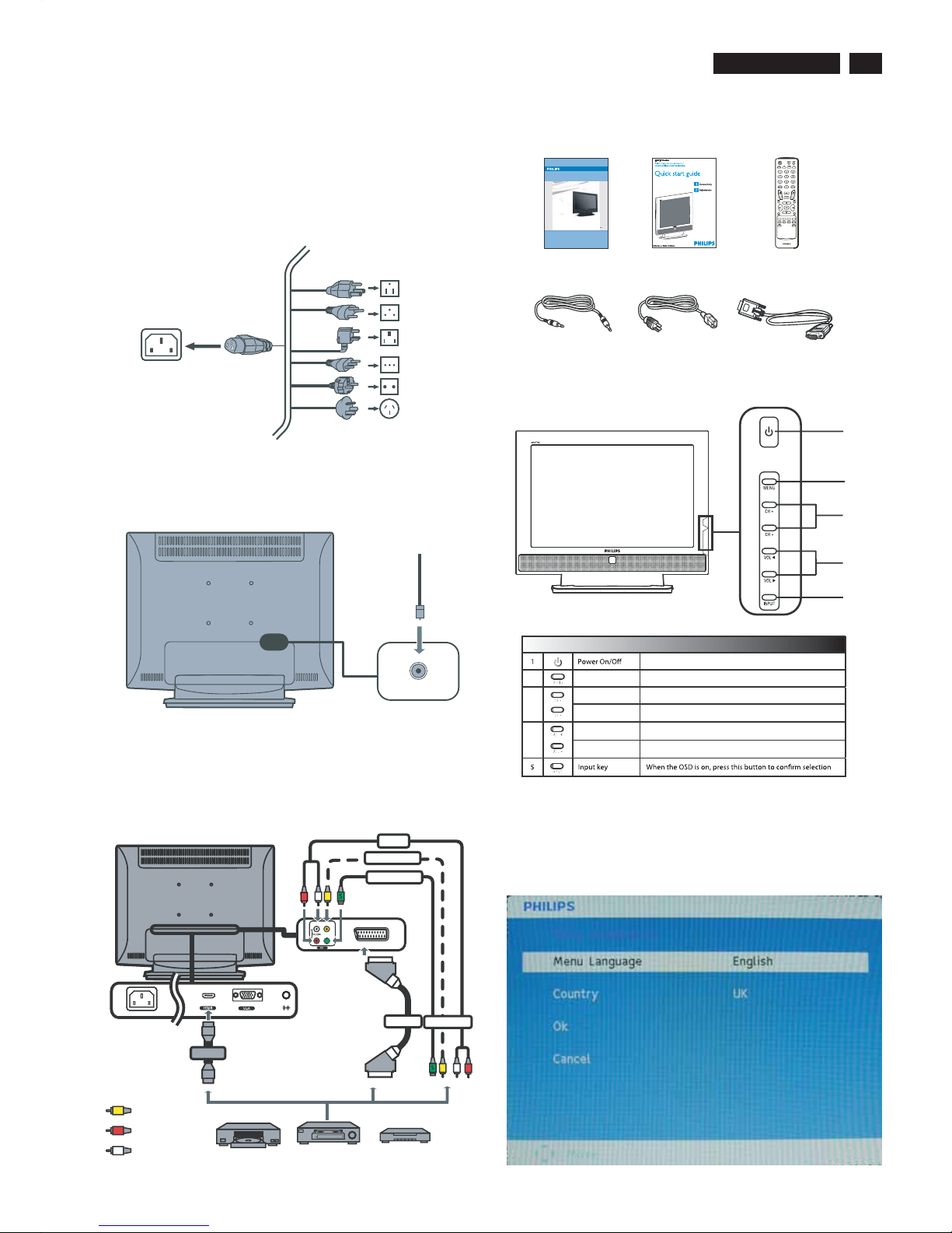
a. Make sure the power cord is plugged into the power
outlet and into the back of the monitor.
b. First, ensure that the power button on the front of the
monitor is in the OFF position, then press it to the ON
position.
No Picture
(Power LED is amber or
yellow)
a. Make sure the computer is turned on.
b. Make sure the signal cable is properly connected to
your computer.
c. Check to see if the monitor cable has bent pins.
d. The Energy Saving feature may be activated.
Screen says a. Make sure the monitor cable is properly connected
to your computer.
(Also refer to the Quick Set-Up Guide).
b. Check to see if the monitor cable has bent pins.
c. Make sure the computer is turned on.
Screen says a. Make sure the monitor cable is properly connected to
your computer. (Also refer to the Quick Set-Up Guide).
b. Check to see if the monitor cable has bent pins.
c. Make sure the computer is turned on.
AUTO button not working
properly
a. The Auto Function is designed for use on standard
Macintosh or IBM-compatible PCs running Microsoft
Windows.
b. It may not work properly if using nonstandard PC or
video card.
Display position is
incorrect
a. Press the Auto button.
b. Adjust the image position using the
Phase/Clock of More Settings in OSD Main Controls.
Image vibrates on the
screen
a. Check that the signal cable is properly connected
to the graphics board or PC.
Vertical flicker appears
a. Press the Auto button.
b. Eliminate the vertical bars using the Phase/Clock
of More Settings in OSD Main Controls.
Horizontal flicker appears
a. Press the Auto button.
b. Eliminate the vertical bars using the Phase/Clock
of More Settings in OSD Main Controls.
Common Problems
Imaging Problems

10 190TW8 TV
Definition of Pixel Defects
This section explains the different types of pixel defects and
defines acceptable defect levels of each type. In order to
quality for repair or replacement under warranty, the number
of pixel defects on a TFT LCD panel must exceed these
acceptable levels.
1. Definition of Pixels and Sub-pixels
A pixel, or picture element, is composed of three sub pixels
in the primary colors of red, green and blue. Many pixels
together form an image. When all sub pixels of a pixel are lit,
the three colored sub pixels together appear as a single
white pixel. When all are dark, the three colored sub pixels
together appear as a single black pixel. Other combinations
of lit and dark sub pixels appear as single pixels of other
colors.
2. Types of Pixel Defects
Pixel and sub pixel defects appear on the screen in different
ways. There are two categories of pixel defects and several
types of sub pixel defects within each category.
Bright Dot Defects
Black Dot Defects
Bright dot defects appear as pixels or sub pixels that are
always lit or 'on'. That is, a bright dot is a sub-pixel that
stands out on the screen when the monitor displays a dark
pattern. There are the types of bright dot defects:
One lit red, green or blue sub pixel
Two adjacent lit sub pixels:
-Red+Blue=Purple
- Red + Green = Yellow
- Green + Blue = Cyan (Light Blue)
Three adjacent lit sub pixels
(one white pixel)
Black dot defects appear as pixels or sub pixels that are
always dark or 'off'. That is, a dark dot is a sub-pixel that
stands out on the screen when the monitor displays a light
pattern. These are the types of black dot defects:
One dark sub pixel
Two or three adjacent
dark sub pixels
A red or blue bright dot must be more than 50
percent brighter than neighboring dots while a
green bright dot is 30 percent brighter than
neighboring dots.
subpixel subpixel subpixel
RGB
RGB
Pixel
R
G
B
P
YC
W
The screen is too bright
or
too dark
Adjust the contrast and brightness on On-Screen
Display.(The backlight of the LCD monitor has a fixed life
span. When the screen becomes dark or begins to flicked,
please contact your sales representative).
An after-image appears
If an image remains on the screen for an extended
period of time, it may be imprinted in the screen
and leave an after-image. This usually disappears
after a few hours.
An after-image remains
after
the power has been
turned off
This is characteristic of liquid crystal and is not
caused by a malfunction or deterioration of the
liquid crystal. The after-image will disappear after
aperoidoftime.
Green, red, blue, dark,
and
white dots remains
The remaining dots are normal characteristic of
the liquid crystal used in today’s technology.
For further assistance, refer to the Consumer Information Centers list
and contact your local Philips distributor.

190TW8 TV
Definition of pixel defects 11
3. Proximity of Pixel Defects
Because pixel and sub pixels defects of the same type that
are near to one another may be more noticeable, Philips also
specifies tolerances for the proximity of pixel defects.
Perfect Panel - ISO 13406-2 Class II compliant do-defect-
free-display.
BRIGHT DOT DEFECTS ACCEPTABLE LEVEL
MODEL 190TW8
1 lit subpixel 3 or fewer
2 adjacent lit subpixels 1 or fewer
3 adjacent lit subpixels (one white pixel) 0
Distance between two bright dot defects* >15mm
Total bright dot defects of all types 3 or fewer
BLACK DOT DEFECTS ACCEPTABLE LEVEL
MODEL 190TW8
1 dark subpixel 5 or fewer
2 adjacent dark subpixels 2 or fewer
3 adjacent dark subpixels 0
Distance between two black dot defects* >15mm
Total black dot defects of all types 5 or fewer
TOTAL DOT DEFECTS ACCEPTABLE LEVEL
MODEL 190TW8
Total bright or black dot defects of all types 5 or fewer
Note:
* 1 or 2 adjacent sub pixel defects = 1 dot defect

12 190TW8 TV Wiring Diagram
(CON2, 4 PIN) (CN4, 5 PIN)
(J1, 10 PIN)
(CN1, 10 PIN)
(CN3, 30 PIN)
(CN101, 10 PIN)
(CN102) (CN103) (CN104) (CN105)
(CN1, 5 PIN)
(CN1, 8 PIN)
Scaler/B P.C.B
Power/B P.C.B
Panel
Speaker-R
Speaker-L LED/B P.C.B

13
190TW8 TV
Mechanical Instructions
DISASSEMBLY PROCESS
Fig. 1
Fig. 2
2.Take off rear cover.
Fig. 3
3. Disconnect the cables.
1. Lay down LCD TV, all tools prepared, remove 7pcs screws
from rear cover.
Fig. 4
4. Disconnect the lamp cables.
Fig. 5
5. Disconnect the LVDs cable, and take off PCB shielding.
Fig. 6
6. Remove 4pcs screws from top and down side panel.

190TW8 TV Mechanical Instructions
Fig.10
10. Remove 3pcs screws from left side of bezel.
Fig. 11
11. Remove 3pcs screws from right side of bezel.
Fig.12
12. Separate bezel from panel.
Fig. 7
Fig. 8
8. Remove 8pcs screws from Speakers, and take off them.
Fig. 9
9.Disconnect the cable from Button/B.
7. Remove 2pcs screws from LED/B, and take off it.
14

15
190TW8 TV
Fig 16
16. Remove 8pcs screws from Main/B and Power/B.
Fig 17
17. Disconnect Main/B and Power/B.
Fig 18
18. The Main/B.
Mechanical Instructions
Fig.13
13. Remove 2pcs screws from left side of panel bracket.
Fig 14
14. Remove 2pcs screws from right side of bracket.
Fig 15
15. Remove 3pcs screw screws from connector.

190TW8 TV Mechanical Instructions
16
Fig. 19
19. The Power/B.
Fig 20
20. The LED/B.
Fig. 21
21. The Button/B.

190TW8 TV
Electronic Instruction 17
F/W upload instruction
Configuration and procedure(ISP tool)
Purpose and Scope
This document contains introduction the user update firmware
environment and run it on MTK tool.
Prepare to update firmware using ISP board
1. Connection ISP board between PC side and TV side.
* Using USB cable connect between ISP board and PC side, see
figure 1.
* Connect ISP board and TV set by VGA cable, see figure 1
Figure 1
2. How to update firmware:
* Make sure ISP board and TV set are connection.
* Enter factory mode:
A. Use remote control, press “ MENU” key to show use OSD menu
and then key “5588”.
B. Factory mode OSD display when setting OK.
* Executing MTK update tool
MTK tool
* Select com Port and Baud rate
* Press Reset icon
The error message will show on screen when communicate NG.
* Press lightning icon to enter update page.
* Press Browse to choose firmware file.
* Press upgrade to update firmware.
If upgrade fail please to lower Baud rate, then AC power off and
turn on again. Then follow update flow to upgrade firmware again.
Figure 2 Update page
* When update finish, then AC power off and turn on again,
see figure 3.
Figure 3. Finish update firmware illustration

18 190TW8 TV Electronic Instructions
Electronic instruction
White balance adjusted flow
The purpose of alignments is for the input signal and color
temperature adjustment.
Environment
Equipment Requirements:
Astro VG-848 or VG-859
Minolta CA-210
Fluke 54200
White balance adjusted flow:
Annex 1
1. Factory mode command:
Remote Key: MENU + 5588
2. Make sure user mode at default values
Annex 2:
1. Example
E9P-PT: 1440*900@60
2. Pattern may be changed for different model.
5. Disc Pattern
Annex 3:
1. There are two input source must be done white balance
adjustment
Example: E9P-PT
A. VGA: 1440*900@60
B. AV: PAL(BG)
2. VGA adjusted value for: VGA(and DVI)
3. AV(CVBS) adjusted value for: ATV, CVBS, S-Video, SCART-
RGB and HDMI
Annex 4(White point)
1. Set R/G/B offset value to 128
2. Adjust R/G/B gain value to find the saturation point
3. Follow “White Balance Adjust” rule to adjust white balance
Annex 5(Dark point)
1. Keep offset max. Value at128
2. Follow “White Balance Adjust” rule to adjust white balance
Annex 6
1. Save adjusted value
2. Change color temp to Warm/Standard/Cold
3. Adjust RG, GG, BG, RO, GO, BO
4. Adjust CT values only to meet white spec
Annex 7
1. Change input to VGA/AV(CVBS)
Annex 8
1. Change input source to SCART-RGB to do auto Calibration
2. Timing:
SCART: PAL(BG)
3. Pattern may be changed for different mode
Gray Scale Pattern
ENTER FACOTRY MODE (Annex 1)
Input VGA source timing: (Annex 2) pattern: 5 Disc
Auto Calibration
Input VGA source timing: (Annex 3) pattern: 100% white
Input AV(CVBS) source PAL(BG) or NTSC(M) pattern: 100% white (Annex 3)
White balance adjust (Annex 4)
Check white spec (xy)
Input VGA source timing: (Annex 3) pattern: 25% white
Input AV(CVBS) source PAL(BG) or NTSC(M) pattern: 25% white (Annex 3)
White balance adjust (Annex 5)
Check white spec(xy)
Save adjusted values Change color temperature (Warm/Standard/Cold)
(Annex 6)
Change input source VGA/AV(CVBS) (Annex 7)
Input SCART or YPbPr source timing: PAL(BG)/480p pattern: Gray Scale (Annex 8)
Auto Calibration
Check Brightness spec (Annex 9)
End process
Out spec
In spec
Out spec
In spec
Change input source
Change color temp
Out spec (Annex 10)
In spec

190TW8 TV
Electronic Instruction 19
Annex 9
1. In Standard mode
2. MENU/Picture/Default Setting
3. Change pattern level to 255(100%)
4. Check brightness whether over spec(250 cd/m² for E9P-PT)
Annex 10
1. Replace panel
2. Repeat white balance flow
Target value Philips (E9P-PT)
White Balance Adjust :
1. x > (=), y > (=) :
A. Fix B value
b. Decrease R value to reduce x value
c. Decrease G value to reduce y value
d. If meet spec than OK
2.x>(=),y<:
a. Fix G value
b. Decrease B value to increase x, y value and let y value to
meet spec
c. Decrease R value to reduce x value
d. If meet spec than OK
3.x<,y>(=):
a. Fix R value
b. Decrease B value to increase x, y value and let x value to
meet spec
c. Decrease G value to reduce y value
d. If meet spec than OK
If you have not CA-110, the following R,G and B values are for
your reference.
4.x<,y<:
a. Decrease B value to increase x, y value and let x = spec, y
>(=) spec or x >(=) spec, y = spec
b. If x = spec, y >(=) spec :
1) Decrease G value to reduce y value
2) If meet spec than OK
c. If x >(=) spec, y = spec :
1) Decrease R value to reduce x value
2) If meet spec than OK
Philips
Color Name Warm Standard Cold
Color Temp 6500K 7500K 9300K
X0.313 0.300 0.285
Y0.329 0.310 0.293
Factory Tolerance dx, dy +-0.007 +-0.007 +-0.007
Shipment Tolerance dx, dy +-0.015 +-0.015 +-0.015
Brightness(Level 255) 270(cd/m²) up 250(cd/m²) up 200(cd/m²) up
19 inch
Color Name
Warm 135 131 137 124 128 117
Standard 120 117 137 125 127 110
Cold 107 110 137 128 126 112
Gain Offset
AV Source
Color Name
Warm 128 125 128 123 128 122
Standard 121 116 128 123 127 128
Cold 108 107 128 124 128 128
Gain Offset
VGA Source
Item1234RX
X > (=) > (=) < <
Y>(=)<>(=)< G Y
Rvv - o
Gv - vo X
B-vvv Y
B

20 190TW8 TV DDC Data
Mfg. Name
Product Code
Serial Number
Mfg, Week
Mfg, Year
Analog DDC Signal Level
Input Support
Feature Support
Display Type
Image Size :
Red x
Red y
Green x
Green y
Blue x
Blue y
White x
White y
H . Pixels
Refresh rate
V Pixel
H . Pixels
Refresh rate
V Pixel
H . Pixels
Refresh rate
V Pixel
H . Pixels
Refresh rate
V Pixel
H . Pixels
Refresh rate
V Pixel
H . Pixels
Refresh rate
V Pixel
H . Pixels
Refresh rate
V Pixel
Horizontal Image Size
Vertical Image Size
Active Pixels
V Active Lines
H Blank
V Blank
H Sync Offset
V Sync Offset
H Sync Plus Width
V Sync Plus Width
H Border
V Border
Established Timeings
Standard Timings
Block #1
: PHL
: 0864
: 72300001
:23
: 2007
: 0.700 , 0.300
: Separate Sync.
: Stand By, Suspend Active Off /Very
Low Power ,
: RGB Color
Max Hor.(cm) : 41
Max Ver.(cm) : 25
Gamma Value *100 : 220
: 0.647
: 0.334
: 0.284
: 0.607
: 0.151
: 0.071
: 0.313
: 0.329
: 720 x 400 @70Hz [ IBM VGA]
: 640 x 480 @60Hz [ IBM VGA]
: 640 x 480 @67Hz [ Mac2]
: 640 x 480 @72Hz [ VESA]
: 640 x 480 @75Hz [VESA]
: 800 x 600 @56Hz [ VESA]
: 800 x 600 @60Hz [VESA]
: 800 x 600 @72Hz [ VESA]
: 800 x 600 @75Hz [ VESA]
: 832 x 624 @70Hz [Mac2]
: 1024 x 768@60Hz [VESA]
: 1024 x 768@70Hz [VESA]
: 1024 x 768 @75Hz [ VESA]
: 640
:85
: 480
: 800
:85
: 600
: 1024
:85
: 768
: 1280
:60
: 720
: 1280
:75
: 720
: 1440
:60
: 900
: 1440
:75
: 900
: 410mm
: 256 mm
: 1440
: 900
: 464 Pixels
: 34 Lines
: 80 Pixels
: 3 Lines
: 152 Pixels
: 6 Lines
: 0 Pixels
: 0 Lines
Pixels Clock
Refresh Mode
Stero
Refresh Mode
Stero
V Polarity(+) , Digital
Separate
Monitor Range Limits :
Max Pixels Clock
Monitor Name
ASCII String
EDID CODE:
: 106.50 Mhz
: Non-Interlaced
: None
: Non-Interlaced
: None
Min V Rate(Hz) : 50
Max V Rate(Hz) : 76
Min H Rate(KHz) : 30
Max H Rate(KHz) : 83
: 140
: Philips 190TW
: Philips
0123456789ABCDEF
0 00FFFFFFFFFFFF 00 410C64 08 E1 35 4F 04
10 17 11 01 03 08 29 19 78 EA EE D5 A5 55 48 9B 26
20 12 50 54 BF EE 00 31 59 45 59 61 59 81 C0 81 CF
30 95 00 95 0F 01 01 9A 29 A0 D0 51 84 22 30 50 98
40 36 00 9A 00 11 00 00 1C 00 00 00 FD 00 32 4C 1E
50 53 0E 00 0A 20 20 20 20 20 20 00 00 00 FC 00 50
60 68 69 6C 69 70 73 20 31 39 30 54 57 00 00 00 FE
70 00 50 68 69 6C 69 70 73 0A 20 20 20 20 20 00 77
This manual suits for next models
1
Table of contents
Other Sharp TV manuals

Sharp
Sharp 21K-FG1RU User manual

Sharp
Sharp SX80J9 User manual

Sharp
Sharp 37DT User manual

Sharp
Sharp LC-24CHG6001K User manual

Sharp
Sharp 70GS-61SC User manual

Sharp
Sharp 21K-FD3RU User manual

Sharp
Sharp LC-70LE632U User manual

Sharp
Sharp LC-32CHE5100E User manual

Sharp
Sharp 29LF-92E User manual

Sharp
Sharp 20PL84 User manual

Sharp
Sharp LC-65UI7252K User manual

Sharp
Sharp 21HS-50H User manual

Sharp
Sharp CX68KF5 User manual

Sharp
Sharp Aquos LC-60LE830E User manual

Sharp
Sharp 42CJ1I Technical manual

Sharp
Sharp 26SL72M User manual

Sharp
Sharp LC-32A40L User manual

Sharp
Sharp 28LF-96EC User manual

Sharp
Sharp cx68n5 User manual

Sharp
Sharp LC-C4254U - 42" LCD TV User manual