Sharp 25WG3 User manual

1
25WG3
SY8A725WG3///
SERVICE MANUAL
SHARP CORPORATION
COLOURTELEVISION
Chassis No. SS-1
MODEL
The chassis in this receiver is partially hot. Use an isolation transformer between the line cord plug and power
receptacle, when servicing this chassis.
To prevent electric shock, do not remove cover. No user-serviceable parts inside. Refer servicing to qualified
service personnel.
WARNING
Intheinterestsofuser-safety(Requiredbysafetyregulationsinsomecountries)thesetshouldberestoredtoitsoriginal
condition and only parts identical to those specified be used.
CONTENTS Page
Page
• FEATURE ............................................................2
• SPECIFICATIONS ...............................................2
• IMPORTANT SERVICE NOTES ......................... 3
• ADJUSTMENT PRECAUTIONS ......................... 3
• SERVICE MODE..................................................4
• SERVICE ADJUSTMENT ................................... 7
• TROUBLESHOOTING ...................................... 13
• SOLID STATE DEVICE BASE DIAGRAM ........ 14
• WAVEFORMS ...................................................15
• DESCRIPTION OF SCHEMATIC DIAGRAM.... 15
• BLOCK DIAGRAM .............................................16
• CHASSIS LAYOUT ............................................22
• SCHEMATIC DIAGRAM ................................... 24
• PRINTED WIRING BOARD ASSEMBLIES....... 32
• PARTS LIST ......................................................37
25WG3
COLOUR TELEVISION MODEL 25WG3SERVICE MANUAL

2
25WG3
FEATURE
• PAL B/G, AV NTSC System
• Auto Search Tuning System
• 100-CH Program Memory
• AV Stereo sound
• High Contrast Picture (Black Stretch Circuit)
• CATV (Hyper Band) Ready<Used Frequency Synthesizer Tuner>
• 7 Mode Surround system
• Picture Signal Improvement Circuit
• 2 Language OSD
• On Timer/ Sleep Timer/ Reminder Timer
• Picture Noise Reduction Circuit
• Blue Back Noise Mute
• Front AV-In & Rear AV-In/Out Terminals
SPECIFICATIONS
Convergence ........................................................................Self Convergence System
Focus ............................................................... Bi-Potential, Uni-Potential Electrostatic
Sweep Deflection ............................................................................................Magnetic
Intermediate Frequency
Picture IF Carrier........................................................................................38.9 MHz
Sound IF Carrier ..............................................................................33.16/33.4 MHz
Colour Sub-Carrier ...................................................................................34.47 MHz
Power Input .................................................................... AC 110-240V, 50/60Hz (Auto)
Power Consumption .............................................................................................130W
Audio Power Output Rating.................................................................. 7.5 W x 2(Max)
Speaker
Size ......................................................................................... 10 cm Round x 2pcs.
Voice Coil Impedance......................................................................8 ohm at 400 Hz
Aerial Input Impedance .................................................................75 ohm Unbalanced
Receiving Channels
PAL-B/G
VHF .......................................................... E2(44.25MHz) thru E12(463.25 MHz)
UHF..................................................... E21(471.25 MHz) thru E69(863.25 MHz)
Dimensions (Approx.)........................................574.0 (W) x 564.5 (H) x 499.0 (D) mm
Weight (Approx.) .................................................................................................. 28 kg
Cabinet Material ................................................................................................Plastics
Specifications are subject to change without notice.

3
25WG3
ADJUSTMENT PRECAUTIONS
This model’s setting are adjusted in two different ways: through the I2C bus
control and in the conventional analog manner. The adjustments via the I2C bus
control include preset-only items and variable data.
1. Calling the service mode by the microprocessor.
(1) Set the switch S1006 to the service mode position, and the microprocessor is
put service mode. (Adjustment through the I2C bus control)
(2) Press the CH UP key on the remote controller to get ready to select the mode
one by one.
(3) PresstheCHDOWN keyontheremotecontrollertoselectthemodesreversely
one by one.
(4) Using the VOLUME UP/ VOLUME DOWN key on the remote controller, the
data can be modified.
(5) Set the switch S1006 to the normal mode (OFF) position, and the microproc-
essor is put out of the service mode.
2. Factory Presettings.
(1) Set the switch S1006 to the service mode position and turn on the main power
switch. Initial values are automatically preset only when a new E2PROM is
used (judgement with the first 4 bytes).
(2) The initial data are preset as listed in page 5~6.
(3) Make sure the data need modify or not (Initial data).
IMPORTANT
Note: Once the chassis has been put together and ready to be POWER ON for the
FIRST TIME, make sure to set the switch S1006 to the service mode position
first and then turn on the main power switch (See 2-(1) above).
IMPORTANT SERVICE NOTES
Maintenance and repair of this receiver should be done by quali-
fied service personnel only.
SERVICING OF HIGHVOLTAGE SYSTEM AND PICTURE
TUBE
When servicing the high voltage system, remove static charge from it by con-
necting a 10k ohm Resistor in series with an insulated wire (such as a test
probe) between picture tube dag and 2nd anode lead.(AC line cord should be
disconnected from AC outlet.)
1. Picture tube in this receiver employs integral implosion protection.
2. Replace with tube of the same type number for continued safety.
3. Do not lift picture tube by the neck.
4. Handle the picture tube only when wearing shatterproof goggles and after
discharging the high voltage completely.
X-RAY
This receiver is designed so that any X-Ray radiation is kept to an absolute
minimum. Since certain malfunctions or servicing many produce potentially
hazardous radiation with prolonged exposure at close range, the following pre-
cautions should be observed:
1. When repairing the circuit, be sure not to increase the high voltage to more
than 32.0 kV (at beam 0µA) for the set.
2. To keep the set in a normal operation, be sure to make it function on 29.0 ±
1.5kV (at beam 1300µA) in the case of the set.The set has been factory-
Adjusted to the above mentioned high voltage.
3. Donotsubstituteapicturetube with unauthorizedtypesand/orbrandswhich
may cause excess X-Ray radiation.
BEFORE RETURNINGTHE RECEIVER
Before returning the receiver to the user, perform the following safety
checks.
1. Inspect all lead dress to make certain that the leads are not pinched or that
hardware is not lodged between the chassis and other metal parts in the
receiver.
2. Inspect all protective device such as non-metallic control knobs, insulating
fishpapers, cabinet backs, adjustment and compartment covers or
shields, isolation resistor- capacity networks, mechanical insulators etc.

4
25WG3
SERVICE MODE
1.) In the Service Mode, Key is used to select the mode in the following order.
AKB/BKGD
MODE 50Hz ADJ
MODE EAST-WEST
MODE VERTICAL
MODE
NVM
MODE 60Hz ADJ
MODE
OPTION ADJ
MODE AV/IGR
MODE SUB ADJ
MODE AGC/VCO
MODE
FORWARD: CH UP
REVERSE: CH DOWN
AKB/BKGD MODE
. WHITE POINT (G)
. WHITE POINT (B)
. AKB ON/OFF
KEY
WHITE-POINT(G)
WHITE-POINT(B)
AKB
UP
2 KEY
3 KEY
8 KEY
DOWN
5 KEY
6 KEY
ON/OFF
In the direction of arrow: CH UP key
In the opposite direction : CH DOWN key
* The character in parentheses appear on the on-screen display.
50Hz ADJ MODE
V-SLOPE (V-SLOPE)
H-SHIFT 50Hz (H-SIFT50)
V-SHIFT 50Hz (V-SIFT50)
EAST-WEST ADJ MODE
WIDTH (WIDTH)
PARABORA/WIDTH (PARA)
CORNER PARABORA (CORNER)
TRAPEZIUM (TRAPE)
In the direction of arrow: CH UP key
In the opposite direction: CH DOWN key
* The character in parentheses appear on the on-screen display.
VERTICAL ADJ MODE
V-AMP (V-AMP)
S-CORRECTION
(S-COR)
SUB ADJ MODE
SUB CONTRAST
(SUB CON)
SUB COLOUR
(SUB COL)
SUB BRIGHTNESS
(SUB BRI)
SUB TINT (SUB TIN)
60Hz ADJ MODE
H-SHIFT 60 (H-SIFT60)
V-SHIFT 60 (V-SIFT60)
AV/IGR ADJ MODE
RF SUB VOLUME
(RF SUB VOL)
SP SUB VOLUME
(SP SUB VOL)
AV TINT (AV TINT)
AV SHARPNESS
(AV SHARP)
IGR BALANCE
(IGR LEVEL)
IGR SEPARATION
(IGR STEREO)
AGC/VCO ADJ MODE
AGC (AGC)
AUTO VCO (AUTO VCO)
MANUAL VCO (MANUAL VCO)
OPTION ADJ MODE
SECAM ON/OFF(SECAM)
M ON/OFF (M)
NICAM AUTO / I / B/G (NICAM)
PSI ON/OFF (PSI)
Y-DELAY (Y-DELAY)
PIP ON/OFF (PIP)
TUNER SHARP/MURATA(TUNER)
TEMP (TEMP)
LANGUAGE (LANG)
TDA7429 ON /OFF (TDA7429)
MONOBILIGUA ON/OFF(MONOBI)
AV2 ON/OFF (AV2)
S-SYSTEM (S-SYS)
C-SYSTEM (C-SYS)
FAVOURITE CH (FAVOURITE)

5
25WG3
AKB ON/OFF ON
WHITE POINT (R) 0~ 63 32
WHITE POINT (G) 0~ 63 32
WHITE POINT (B) 0~ 63 32
V-SLOPE 0~ 63 25
H-SHIFT 50Hz 0~ 63 25(TV)
V-SHIFT 50Hz 0~ 63 32 (TV)
WIDTH 0~ 63 48
PARA 0~ 63 36
CORNER 0~ 63 28
TRAP 0~ 63 32
V-AMP 0~ 63 17
S-COR 0~ 63 15
H-SHIFT 60Hz 0~ 63 31(TV)
V-SHIFT 60Hz 0~ 63 26(TV)
AGC 0~ 63 15
AUTO VCO 0~127 NG 55
MANUAL VCO 0~127 55
SUB-CONTRAST 0~ 63 63
SUB COLOUR 0~ 63 19
SUB BRIGHT 0~ 63 31
SUB TINT 0~ 63 27
RF SUB VOLUME 0~ 63 35
SP SUB VOLUME 0~ 63 55
AV TINT 0~ 63 00
AV SHARP 0~ 63 00
IGR LEVEL 0~10 05
IGR STEREO 0~ 31 24
SECAM ON/OFF ON
M ON/OFF ON
NICAM AUTO/BG/I AUTO
PSI ON/OFF ON
Y-DELAY 0~ 15 09(TV), 09(AV)
PIP ON/OFF OFF
TUNER SHARP/MURATA SHARP
TEMP 0~1 0
LANG ON/OFF ON
TDA7429 ON/OFF ON
MONOBI ON/OFF ON
AV2 ON/OFF ON
S-SYS ON/OFF ON
C-SYS ON/OFF ON
FAVOURITE CH ON/OFF ON
NVM - -
E2PROM ITEMS DATA LENGTH INITIAL DATA REMARK
MCL1 (R/C CODE =117) MCL2 (R/C CODE=169)
CH-NO Fv (MHz) SOUND SYS CH-NO Fv (MHz) SOUND SYS
1). In service mode, After execute select POS 1, setting the following data in
E2PROM.
INITIAL SETTING OF E2PROM MCL1 & MCL2 CHANNEL SETTING
1 48.25 AUTO 1 46.25 AUTO
2 62.25 AUTO 2 64.25 AUTO
3 77.25 AUTO 3 86.25 AUTO
4 175.25 AUTO 4 95.25 AUTO
5 182.25 AUTO 5 138.25 AUTO
6 183.25 AUTO 6 175.25 AUTO
7 191.25 AUTO 7 182.25 AUTO
8 196.25 AUTO 8 189.25 AUTO
9 210.25 AUTO 9 196.25 AUTO
10 224.25 AUTO 10 209.25 AUTO
11 471.25 AUTO 11 216.25 AUTO
12 487.25 AUTO 12 SKIP OFF FREE
13 503.25 AUTO 13 SKIP OFF FREE
14 575.25 AUTO 14 SKIP OFF FREE
15 599.25 AUTO 15 SKIP OFF FREE
16 621.25 4.5 M 16 SKIP OFF FREE
17 639.25 AUTO 17 SKIP OFF FREE
18 703.25 AUTO 18 527.25 AUTO
19 735.25 AUTO 19 847.25 AUTO
20 767.25 AUTO 20 48.25 AUTO
21 815.25 AUTO 21 175.25 AUTO
22 855.25 AUTO 22 210.25 AUTO
23 855.25 AUTO 23 224.25 AUTO
24 55.25 4.5 M 24 575.25 AUTO
25 83.25 4.5 M 25 599.25 AUTO
26 183.25 4.5 M 26 767.25 AUTO
27 193.25 4.5 M 27 183.25 4.5 M
28 217.25 4.5 M 28 193.25 4.5 M
29 471.25 4.5 M 29 112.25 AUTO
30 477.25 4.5 M 30 168.25 AUTO
31 693.25 4.5 M 31 SKIP OFF FREE
32 SKIP OFF FREE 32 294.25 AUTO
33 112.25 AUTO 33 463.25 AUTO
34 169.25 AUTO 34 174.95 AUTO
35 SKIP OFF FREE 35 175.55 AUTO
36 294.25 AUTO 36 SKIP OFF FREE
37 463.25 AUTO 37 SKIP OFF FREE
38 SKIP OFF FREE 38 SKIP OFF FREE
39 647.25 AUTO 39 SKIP OFF FREE

6
25WG3
MCL1 (R/C CODE =117) MCL2 (R/C CODE=169)
CH-NO Fv (MHz) SOUND SYS CH-NO Fv (MHz) SOUND SYS
40 663.25 AUTO 40 SKIP OFF FREE
41 679.25 AUTO 41 SKIP OFF FREE
42 174.95 AUTO 42 SKIP OFF FREE
43 175.55 AUTO 43 SKIP OFF FREE
44 SKIP OFF FREE 44 SKIP OFF FREE
45 SKIP OFF FREE 45 SKIP OFF FREE
SKIP OFF FREE SKIP OFF FREE
99 SKIP OFF FREE 99 SKIP OFF FREE
NO ITEMS SETTING 1 SETTING 2
1 SKIP POS 0 ON ->
2 SKIP POS 1 ~99 OFF ->
3 AFT ON ->
4 COLOUR SYSTEM AUTO ->
5 SOUND SYSTEM BG BG
6 IGR FORCE FM OFF ->
7 IGR STEREO STEREO ->
8 IGR BILINGUAL MAIN ->
9 NICAM FORCE FM OFF ->
10 NICAM BILINGUAL M1 ->
11 LAST POWER ON ->
12 LAST TV/AV TV ->
13 DIGIT 2 DIGIT ->
14 LANGUAGE ENGLISH THAI
15 BLUE BACK ON ->
16 AV SELECT ON/OFF OFF ->
17 AV SELECT STD/GAME STD ->
18 LAST POSITION 1 ->
19 LAST FB POSITION 1 ->
20 VOLUME 0 (MIN) ->
21 BALANCE 0 (L,R) ->
22 BASS 0 ->
23 MIDDLE 0 ->
24 TREBLE 0 ->
25 SURROUND OFF ->
26 CONTRAST 63 ->
27 COLOUR 31 ->
28 BRIGHTNESS 31 ->
29 TINT 31 ->
30 SHARPNESS 31 ->
31 TIMER CLEAR ->
32 SAVE OFF ->
33 PICTURE NR OFF ->
34 INSET TINT 31 ->
35 PIP DISPLAY POS SE ->
36 PIP SIZE L ->
37 PIP LAST POS 1 ->
38 PIP LAST TV/AV TV ->
39 FREEZE OFF ->
40 MONORAL BILINGUAL S 1 ->
SHIPPING SETTING IX3097CEN2

7
25WG3
SERVICE ADJUSTMENT
NO
ADJUSTMENT POINT WAVEFORM OR OTHERS
1
VCO ADJUSTMENT
(I
2
C BUS CONTROL)
1.Receive E-10CH (210.25MHz) "PAL
COLOUR BAR" signal.
2.Call "AUTOVCO" in SERVICE mode. If
the Channel frequency displays on
screen is 210.20MHz, skip (3), (4) & (5)
steps.
3.Press FUNCTION button to call
"DIRECT FREQ IN".
4.Push "2", "1", "0", "2", "0".
5.Then Press FUNCTION again.
6.Press Volume UP to run "AUTO VCO".
Once finishing, "OK" message display
on screen.
Signal Strength: 60 ~ 70 dB
2
AGC ADJUSTMENT
(I
2
C BUS CONTROL)
7.
Receive E-12CH (PAL COLOR BAR) signal.
Signal strength : 57 ±1 dB ( 75ohm open)
8.Connect the oscilloscope to P201
(Tuner’s AGC Terminal) as shown in
Figure 1.
Figure 1
9.Call "AGC" in SERVICE mode.
10. Increase or decrease "AGC" by using
Volume so that obtain the highest
Voltage.
11. Press Volume slowly in the opposite
direction until the voltage drops 0.1V ~
0.3V lower than the highest level.
12. Change the antenna input signal to 63
~ 67dBµV, and make sure there is no
noise.
13. Turn up the input signal to 90 ~ 95 dBµV
to be sure that there is no cross
modulation beat.
ADJUSTMENT CONDITION/PROCEDURE
VCO, AND AGC ADJUSTMENT SOUND ADJUSTMENT
2 SP SUB VOLUME
(I
2
C BUS CONTROL)
5.Receive "COLOUR BAR" signal.
Audio signal: 400Hz, 100%modulation.
(50kHz dev.)
6.Connect Dummy load* to P3304.
7.Connect VTVM’s probe to the P3304.
(1 R, 2 GND, 3 GND, 4 L, 5 NIL, 6 NIL
7 NIL 8 NIL)
8.Call the "SP SUB VOL" in the SERVICE
mode.
9.Increase or decrease "SP SUB VOL" by
using Volume UP/DOWN key, so that
the VTVM should read the value*.
3 NOISE MUTE
CHECKING 10. Receive the 400Hz modulated signal.
11. Turn up the volume control to Maximum
and make sure the sound is heard from
the speakers.Then put the unit in the
no-signal state.
12. Be sure that the sound mute is effective.
13. Finally turn down the volume control to
minimum.
NO
ADJUSTMENT POINT WAVEFORM OR OTHERS
1 RF SUB VOLUME
(I
2
C BUS CONTROL)
1.Receive "PAL COLOUR BAR" signal.
Audio signal:400 Hz, 100% modulated
(50kHz dev.)
2.Connect the Oscilloscope to the Audio
Out (L or R) terminal. (Terminate with
10k ohm impendence).
3.Call the "RF SUB VOL" in SERVICE
mode.
4.Increase or decrease "RF SUB VOL" by
using Volume UP/DOWN key, so that
the 400Hz sine wave be 1.76Vp-p.
Tolerence: 1.76 Vp-p ±0.10 Vp-p.
ADJUSTMENT CONDITION/PROCEDURE
OSCILLOSCOPE
TV SET
BIAS BOX : ABOUT 4.5V
P201
+
-
+
-
1
2
*Note :Terminated 8 ohm
to get 7.75 ±
0.1Vrms.
(L Channel)

8
25WG3
NO
ADJUSTMENT POINT
1 PURITY ADJ. 1. Receive the GREEN -ONLY signal.
Adjust the beam current to ~800µA.
2.Orient the raster rotation to 0 eastward.
3.Degauss the CRT enough with the
degausing coil.
4.Maintain the purity magnet at the zero
magnetic field and keep the static
convergence roughly adjusted.
5.Observe the points a, b, as shown in
Fig.2-1 through the microscope. Adjust
the landings to A rank requirement.
6.Tighten up the deflection coil screws.
Tightening torque : 108N ±20N
(11Kgf ±2Kgf)
7.Make sure the CRT corners landing
meet the A rank requirements. If not,
stick the magnet sheet to correct it.
Note: This adjustment must be done
after warming up the unit for 30
minutes or longer with a beam
current over 1000µA.
Note: Set the service mode by service
switch ( S 1006) then press
factory process R/C RGB key to
change to green only.
* For the following colour press colour key
to change.
ADJUSTMENT CONDITION/PROCEDURE
PURITY ADJUSTMENT
Figure 2-1
WAVEFORM OR OTHERS
Figure 2-2
Rank A (On the right of CRT)
Figure 2-3
Rank A (On the left of CRT)
Text Key "R.G.Cy" Key
can be directly use to
change to other colours
screen.
1.Receive the "CROSSHATCH
PATTERN" signal.
2.Using the remote controller, call
NORMAL mode.
(Static convergence)
1.Turn the 4 - pole magnet to a proper
opening angle in order to superpose the
blue and red colours.
2.Turn the 6 - pole magnet to a proper
opening angle in order to superpose the
green colour over the blue and red
colours.
(Dynamic convergence)
1.Adjust the convergence on the fringes of
the screen in the following steps.
a) Fig. a :Drive the wedge at point "a"
and swing the deflection coil
upward.
b) Fig. b :Drive the wedge at point "a"
and "b" and swing the
deflection coil downward.
c) Fig. c : Drive the "c" wedge deeper
and swing the deflection coil
rightward.
d) Fig. d :Drive the "b" wedge deeper
and swing the deflection coil
leftward.
2.Fix all the wedges on the CRT and apply
glass tape over them.
3.Apply lacquer to the deflection yoke lock
screw, magnet unit ( purity 4 - pole, 6 -
pole magnets ) and magnet unit lock
screw.
Finally received the Red - only and Blue
- only signals to make sure there is no
other colours on the screen.
Figure 4
4-pole Magnet
6-pole Magnet
CRT NECK
Lacquer
Purity Magnet NECK
R
R
G
G
B
B
Figure a
Figure b
BGR
B
G
R
RGB
B
G
R
Figure c
BGR
R
G
B
Figure d
CONVERGENCE ADJUSTMENT
NO
ADJUSTMENT POINT
1
CONVERGENCE ADJ.
(To be done after the
purity adjustment.)
ADJUSTMENT CONDITION/PROCEDURE
WAVEFORM OR OTHERS
Wedge "a"
Wedge "b"
Lacquer
Wedge "c"
About 100˚ About 100˚
Figure 3

9
25WG3
1.Switch TV to VIDEO MODE, Blue Back:
OFF, Without Video Signal.
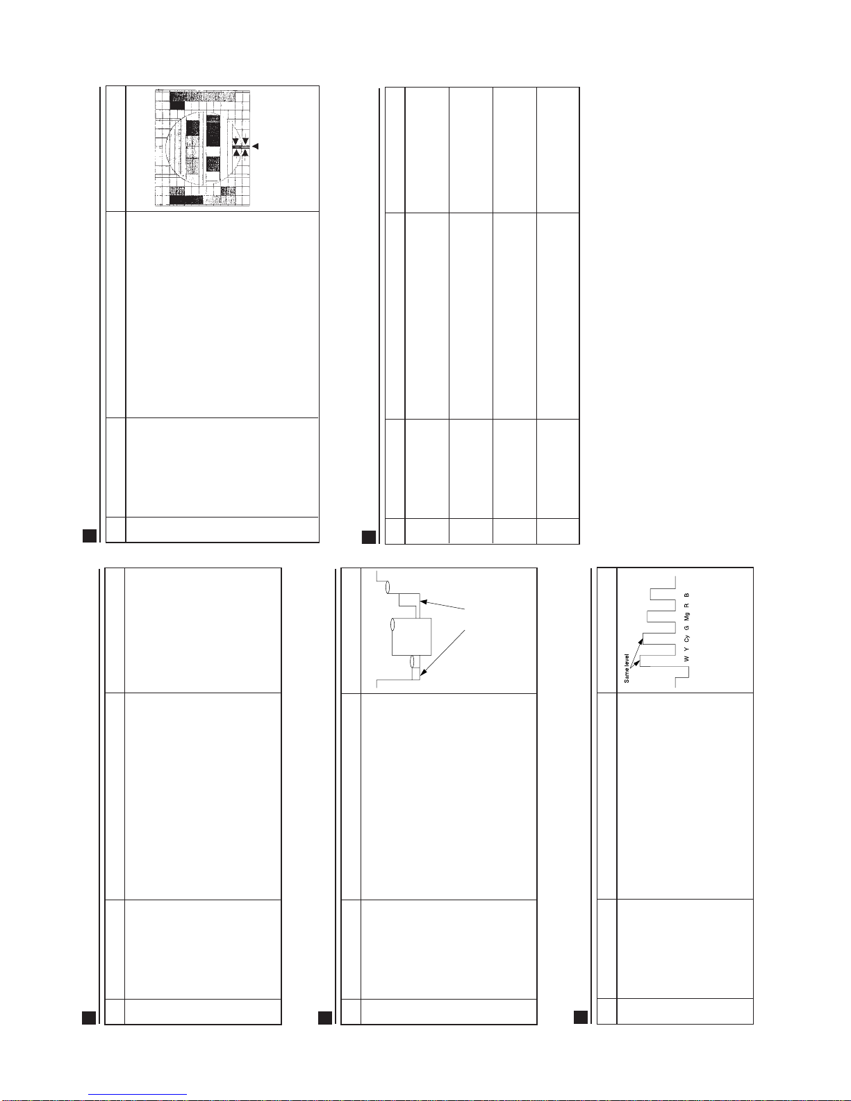
2.Connect the oscilloscope to TP851.
(Use a 10:1 probe)
Range: 500mV/div
Sweep Time: 5ms/div
Press "DC" mode
3.Using the remote controller, call
NORMAL mode.
4.Adjust Screen VR so that the tip of
signal reach 2.5Vdc ±0.1Vdc.
CUT OFF , WHITE BALANCE, SUB - BRIGHT, & FOCUS ADJUSTMENT.
NO
ADJUSTMENT POINT
1
CRT Cut - OFF ADJ.
(I
2
C BUS CONTROL)
ADJUSTMENT CONDITION/PROCEDURE
WAVEFORM OR OTHERS
*Before adjustment ,make
sure that this adjustment
with the initial bus data
"White Point (G)" &
"White Point (B)" are 32.
Figure 5
5.Receive the MONOSCOPE PATTERN
signal.
6.Call the "BKGD" in SERVICE mode.
7.Adjust "White Point (G)", "White Point
(B)" data to have a colour temperature
of 12300k (White) Note.
2 White Balance ADJ.
(I
2
C BUS CONTROL)
Note :White Point (G)
UP " 2 " KEY
DOWN " 5 " KEY
White Point (B)
UP " 3 " KEY
DOWN " 6 " KEY
As the above data can be
UP / DOWN.
*12300k x=272
y=275
(Minolta Colour Analyzer
CA-100)
8.Receive the "CROSSHATCH
PATTERN" Signal.
9.Call the "SUB BRI" in SERVICE mode.
10.Adjust the "SUB-BRI" bus data, so that
the No. 2 line inside the window area
will disappear.
Note: Before starting this adjustment,
warm up the unit for 30 minutes or
longer at a beam current of 1200 ~
1300µA.
3 SUB- BRIGHT ADJ.
(I
2
C BUS CONTROL)
Figure 6
11.Receive the "MONOSCOPE PATTERN"
Signal.
12.Press P-NORMAL key.
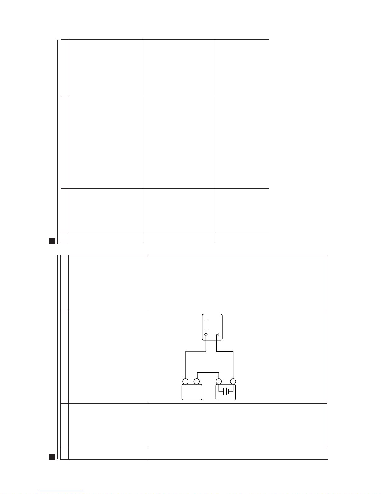
13.Connect the DC Milliammeter between
TP601 (-) and TP602 (+). (Full Scale:
3.0 mA Range).
14.Beam current Must be 1200 ±100µA.
4 BEAM CURRENT
CHECK
1.
Receive the "MONOSCOPE PATTERN"
signal.
2.
Using the remote control, call NORMAL
mode.
3.
Adjustthe FOCUS controlsothat theshaded
area of screen be in optimal focus.
5 FOCUS ADJ.
Figure 7
1.Receive the 50Hz "MONOSCOPE
PATTERN" signal.
2.Call the "V-SIFT 50" in SERVICE mode.
3.Increase or decrease the "V-SIFT 50"
by using Volume UP/DOWN key to
adjust or align the screen center with
the CRT’s geometrical center.
4.Receive the 60 Hz "MONOSCOPE
PATTERN" signal.
5.Call the "V-SIFT 60" in SERVICE mode.
6.Increase or decrease the "V-SIFT 60"
by using Volume UP/DOWN key to
adjust or align the screen center with
the CRT’s geometrical center.
V-SHIFT 60
(I
2
C BUS CONTROL)
1.Receive the "MONOSCOPE PATTERN"
signal.
2.Call the "V-AMP" in SERVICE mode.
3.Increase or decrease the "V-AMP" by
using the volume UP/DOWN key to
adjust the Vertical size until it is 8.5%
overscan.
3 V-AMP
(I
2
C BUS CONTROL)
OVER SCAN: 8.5% ±1.5 %
1.Receive the 50Hz "MONOSCOPE
PATTERN" signal.
2. Call the"H-SIFT 50"IN SERVICE MODE.
3. Increase or decrease the "H-SIFT 50" by
usingtheVolumeUP/DOWNkeytoadjust
or align the left, and right sides of screen
are equal overscan size.
4.Receive the 60Hz "MONOSCOPE
PATTERN" signal.
5. Call the"H-SIFT 60"IN SERVICE MODE.
6. Increase or decrease the "H-SIFT 60" by
usingtheVolumeUP/DOWNkeytoadjust
or align the left and right sides of screen
are equal overscan size.
4 H-SHIFT 50
(I
2
C BUS CONTROL)
H-SHIFT 60
(I
2
C BUS CONTROL)
SPEC: ±2mm
SPEC: ±2mm
1.Receive the "MONOSCOPE PATTERN"
signal.
2.Call the "V-SLOPE" in SERVICE mode.
3.Increase or decrease "V-SLOPE" by
using Volume key so that the center line
of picture matches with the edge of
blanking line.
HORIZONTAL, VERTICAL, DEFLECTION LOOP ADJUSTMENT.
NO
ADJUSTMENT POINT
1 V-SLOPE ADJ.
(I
2
C BUS CONTROL)
ADJUSTMENT CONDITION/PROCEDURE
WAVEFORM OR OTHERS
SPEC: ±1
SCANNING LINE
2 V-SHIFT 50
(I
2
C BUS CONTROL)
1 2 3 4 5

10
25WG3
HORIZONTAL, VERTICAL, DEFLECTION LOOP ADJUSTMENT.
NO
ADJUSTMENT POINT
ADJUSTMENT CONDITION/PROCEDURE
WAVEFORM OR OTHERS
1. Receive the "CROSSHATCH PATTERN"
signal.
2.Call the "S-COR" IN SERVICE mode.
3.Increase or decrease the "S-COR" by
using the Volume UP/DOWN key to get
the best LINEARITY.
4.Adjustment with S-COR: OVERALL
VERTICAL LINEARITY.
5.Readjust the "V-AMP" to make the
overscan 8.5%. Readjust or align "V-
SIFT"to matchthescreen centerwith the
CRT’s geometrical center.
5 S-COR
(I
2
C BUS CONTROL)
V-LINEARITY: ±5% Max
1.Receive the "PAL Color Bar" signal.
2.Using remote controller, call NORMAL
mode.
3.Connect the oscilloscope to TP852
(Red cathode).
Range: 20 V/Div (Using 10:1 Probe)
Sweep: 20 µsec/Div
4.Using the R/C call "SUB COL"
adjustment mode. Adj SUB-COL bus
data, so that the 75% White & Red
portions of PAL Color Bar be at the
same level.
5.Clear the adjustment mode.
PAL CHROMA ADJUSTMENT
NO
ADJUSTMENT POINT
1 SUB COLOUR ADJ.
(I
2
C BUS CONTROL)
ADJUSTMENT CONDITION/PROCEDURE
WAVEFORM OR OTHERS
Cy GB
RMg100% WWY
Same level
Figure 8
1.Receive the AV NTSC 3.58 Colour Bar
signal.
2.Connect the oscilloscope to TP853.
Range: 500mV/Div
Sweep time: 20 µsec/Div
3. Set the "SUB-TIN" mode at service mode.
Adjust the "SUB TIN" bus data so that
the FIRST AND SECOND portions of
the colour Bar are SAME level shown
in Figure 9.
NTSC CHROMA ADJUSTMENT
NO
ADJUSTMENT POINT
1 AV-TINT
(I
2
C BUS CONTROL)
ADJUSTMENT CONDITION/PROCEDURE
WAVEFORM OR OTHERS
Figure 9
Note: Be sure that AV
TINT set to 00 at
SERVICE mode.
(1) Receive the PAL B/G PHILIPS pattern
signal.
(2)
Switch on service mode then press
channel up/down key to select Y DELAY
mode.
(3) Press volume up/down key to select a
suitable number so that luminance delay
similar to color delay, shown as fig. 10.
(4)TheY DELAY data is between 6~8.
(5) Switch off the service mode.
NO
ADJUSTMENT POINT
1 Y DELAY
(I2C DATA)
ADJUSTMENT CONDITION/PROCEDURE
WAVEFORM OR OTHERS
Figure 10
Y DELAY ADJUSTMENT
same distance
1.Call "SECAM" in SERVICE mode.
2.Switch the "SECAM" by using the
Volume UP/DOWN key to "OFF".
OPTION ADJUSTMENT
NO
ADJUSTMENT POINT
1 SECAM SETTING
ADJUSTMENT CONDITION/PROCEDURE
WAVEFORM OR OTHERS
1.Call "M" in SERVICE mode.
2.Switch the "M" by using theVolume
UP/DOWN key to "OFF".
2 M SETTING
1.Call "S-SYS" in SERVICE mode.
2.Switch the "S-SYS" by using the
Volume UP/DOWN key to "OFF".
3 S-SYS SETTING
1.Call "C-SYS" in SERVICE mode.
2.Switch the "C-SYS" by using the
Volume UP/DOWN key to "OFF".
4 C-SYS SETTING

11
25WG3
1.Receive the "COLOUR BAR PATTERN"
signal.
2.Press the CH UP / DOWN key for
PICTURE control setting with the R/C,
select the COLOUR.
3.Increase or decrease the COLOUR by
using the VOLUME UP / DOWN key.
4.Check whether the COLOUR is OK or
not.
2 COLOUR
1.Receive the "MONOSCOPE PATTERN"
signal.
2.Press the CH UP / DOWN key for
PICTURE control setting with the R/C,
select the BRIGHTNESS .
3.Increase or decrease the
BRIGHTNESS by using the VOLUME
UP / DOWN key.
4.Check whether the BRIGHTNESS is OK
or not.
3 BRIGHTNESS
1.Receive the "MONOSCOPE PATTERN"
signal.
2.Press the CH UP / DOWN key for
PICTURE control setting with the R/C,
select the SHARPNESS.
3.Increase or decrease the SHARPNESS
by using theVOLUME UP / DOWN key.
4.Check whether the SHARPNESS is OK
or not.
4 SHARPNESS
1.Receive the "MONOSCOPE PATTERN"
signal.
2.Press the CH UP / DOWN key for
PICTURE control setting with the R/C,
select WHITE TEMP.
3. Increase or decrease the WHITE TEMP
by using theVOLUME UP / DOWN key.
4.Check whether the WHITE TEMP is OK
or not.
5 WHITE TEMP
1.Receive the "MONOSCOPE PATTERN"
signal.
2.Press the CH UP/DOWN key for
PICTURE control setting with R/C,
select the CONTRAST.
3.Increase or decrease the CONTRAST
by using theVOLUME UP / DOWN key.
4.Check whether the CONTRAST is OK
or not.
CHECKING OPERATION (VIDEO & AUDIO)
NO
CHECKING POINT
1 CONTRAST
SETTING CONDITION
WAVEFORM OR OTHERS
1.Receive the "PAL COLOUR BAR"
signal (100% White Color Bar Sound
400 Hz 100% Modulation)
2.Terminate the Video output with a 75
ohm impendence.Make sure the output
is as specified (1.0 Vp-p ±3 dB)
3.Terminate the Audio output with a 10
Kohm impendence.Make sure the O/P
is as specified (1.76 Vp-p ±3 dB).
A/V INPUT/OUTPUT CHECKING
NO
ADJUSTMENT POINT
1 VIDEO & AUDIO
OUTPUT CHECKING
ADJUSTMENT CONDITION/PROCEDURE
WAVEFORM OR OTHERS
1.Using the TV/AV key on the remote
controller, make sure that the modes
change in order of TV, AV1, AV2 & TV
again and that the video & audio output
are according to the input terminal for
each mode.
2 VIDEO & AUDIO
INPUT CHECKING
1.Connect Video signal to FRONT AV
(AV2).
2.Make sure Channel switch from other
channel to AV2 automatically.
3 AUTO SELECT
PROTECTOR OPERATION CHECKING
1.Receive the "MONOSCOPE PATTERN"
signal.
2.Set CONTRAST MAX.
3.Set BRIGHT MAX.
4.While the R or B or G Cathode short to
ground, make sure the protector ON
and switch to standby mode.
NO
ADJUSTMENT POINT
1
BEAM PROTECTOR
ADJUSTMENT CONDITION/PROCEDURE
WAVEFORM OR OTHERS
PROTECTOR OPERATION CHECKING
NO
ADJUSTMENT POINT
ADJUSTMENT CONDITION/PROCEDURE
WAVEFORM OR OTHERS
1.Receive the "MONOSCOPE PATTERN"
signal.
2.Connect output of Bias Box to D601
cathode (D608).
3.Set voltage of Bias Box to 20V and
make sure the protector is work.
2 H, V PROTECTOR
1.Once finish rectified Electrolytic
Capacitor short testing in + B line,
check all possible damaged
components on +B line.
3
OTHER PROTECTOR

12
25WG3
1.Receive the "COLOUR BAR PATTERN"
signal.
2.Press NORMAL key to set the picture
condition to normal .When the
NORMAL key is pressed, all the initial
picture control settings will be preset to
normal setting as listed below:
Contrast: MAX.
Colour: CENTER
Brightness: CENTER
Tint: CENTER
Sharpness: CENTER
CHECKING OPERATION (VIDEO & AUDIO)
NO
CHECKING POINT
6 NORMAL
SETTING CONDITION
WAVEFORM OR OTHERS
All Ch (1~99) will have an OSD display of
the channel number in green colour under
AFT ON condition.
7 CH COLOUR
DISPLAY
If nothing is display mean
contrast,colour, bright,tint,
sharpnessareall in normal
setting.
1.Receive the MUSIC SOUND SIGNAL.
2.Press the CH UP / DOWN key for
SOUND control setting with the R/C,
select the BASS.
3.Increase or decrease the BASS by
using the VOLUME UP / DOWN key.
4.Check whether the BASS (low
frequency) is OK or not.
8 BASS
1.Receive the MUSIC SOUND SIGNAL.
2. Press theCH UP / DOWN key for SOUND
control setting with the R/C, select the
MIDDLE.
3.Increase or decrease the MIDDLE by
using the VOLUME UP / DOWN key.
4.Check whether the MIDDLE (MIDDLE
frequency) is OK or not.
9 MIDDLE
1.Receive the MUSIC SOUND SIGNAL.
2. Press theCH UP / DOWN key for SOUND
control setting with the R/C, select the
TREBLE.
3.Increase or decrease the TREBLE by
using the VOLUME UP / DOWN key.
4.Check whether the TREBLE (HIGH
frequency) is OK or not.
10 TREBLE
1.Receive the MUSIC SOUND SIGNAL.
2. Press theCH UP / DOWN key for SOUND
control setting with the R/C, select the
BALANCE.
3.Increase or decrease the left or right
speaker BALANCE by using the
VOLUME UP / DOWN key.
4.Check whether the BALANCE of left and
right speakers is OK or not.
11 BALANCE
1.Receive the MUSIC SOUND SIGNAL.
2.Press NORMAL key to set the sound
condition to normal .When the
NORMAL key is pressed, all the initial
sound control settings will be preset to
normal setting as listed below:
BASS: CENTER
MIDDLE: CENTER
TREBLE: CENTER
BALANCE: CENTER
NO
CHECKING POINT
12 NORMAL
SETTING CONDITION
WAVEFORM OR OTHERS
If nothing is display mean
contrast,colour,bright,tint,
sharpness are allinnormal
setting.
1. Receive the MUSIC SOUND SIGNAL.
2. Press the CH UP / DOWN key for
SURROUND control setting with the R/C.
3. Press Volume Up to switch Surround
Mode as follows, MOVIE/DISCO/POP/
ROCK/CLASSIC/SPORTS/SIMULATED/
OFF.
4. Makesure eachmodeisworkingproperly.
13 SURROUND
1.Receive the "PAL COLOUR BAR
PATTERN" signal. Press the SYSTEM
key to set the COLOUR SYSTEM
MODE to AUTO mode.Check whether
the colour of the PAL Colour Bar signal
is OK or not.
2.
Receive the "NTSC 4.43 COLOUR BAR"
signal. Press the SYSTEM key to set the
COLOUR SYSTEM mode to AUTO mode.
Check whether the colour of the N4.43
Colour Bar signal is OK or not.
3.
Receive the "NTSC 3.58 COLOUR BAR"
signal. Press the SYSTEM key to set the
COLOUR SYSTEM mode to AUTO
mode.Check whether the colour of the
N3.58 Colour Bar signal is OK or not.
14 COLOUR SYSTEM
1. Press FUNCTION key to select each
modeasfollows,SAVE/ AVSELECT/NR/
BLUE BACK/OSD.
2. Press Volume Up to switch each mode,
make sure each mode is working
properly.
15 FUNCTION
1.Receive "PAL COLOUR BAR" signal.
2. Turn up the volume control to maximum,
make sure the sound is heard from the
speakers. Then put the unit in no signal
state.
3. Be sure that the sound mute is effective.
4. Finally turn down the volume of CTV to
minimum.
16 NOISE MUTE
CHECKING
1. Receive "DUAL SOUND" signal.
2. Press CH UP/DOWN key for SOUND
control setting with the R/C, select
BILINGUAL.
3. Press VOLUME UP/DOWN to select
SOUND 1 & SOUND 2.
4. Check whether SOUND 1 & SOUND 2
are okay separately or not.
17 BILINGUAL

13
25WG3
TROUBLESHOOTING
Figure 1
If bus error happen, the LED RED (pin (30) of IC1001 low) indicator starts flashing and the power is turned off.
The power key is still effective.
E PROM (S24C04A)
IC1002
1 chip IC (TDA8375)
IC201
Sound processor IC (TDA7429S)
IC302
PSI IC (TDA4671)
IC401
PLL (ST6HD64)
TU201
2
Check F750. Blown out.
Replace the fuse.
The fuse is again
blown out.
Check T701 pin(1)
voltage (approx. 310V
at 220VAC).
Check D704, and
IC701, C730, C731.
Check R701, R703 and
D703.
Check D708 and D714.
Check IC703.
Check secondary main + B
(approx. 120V).
D1101 (power LED
green) turn ON ?
Check CRT connector
K1-K5 bias.
Check IC851
and peripheral
parts.
Check (K) wire
and plug.
Horizontal circuit oscillate?
Check IC201,
Q603, IC202
and Q601.
D1101 (power LED red)
turns on or turns
ON/OFF ?
Check the protector
circuit.
Bus error mode.
See Figure 1.
NO RASTER
Normal
Normal
Normal
Normal
Normal
Abnormal
Abnormal
Abnormal
YES
YES
NO
NO
ON/OFF
Does the snow noise appear on
the picture tube at max contrast
and brightness control?
Snow noise increase.
Check the TUNER 33V.
Check IC203,
R227.
Check the tuner AGC.
Check IC201.
Check the
tuner circuit.
NO PICTURE
B
Normal
Normal
Abnormal
Abnormal
No snow noise.
Check the voltage of
S-convertor (12V).
Check IC301, Q202, Q204
and its related parts.
Check IC201 and
peripheral circuit.
Check R318, C303.
Does noise or signal appear at pin (27) of IC201?
Does noise or signal appear at pins (29), (30)
of IC302?
Does noise or signal appear at pins (2), (5)
of IC3301?
Check (FS) connector, IC3301 and their
peripheral circuit.
Check IC302 and peripheral circuit.
Does noise or signal appear at
pin (16) of IC201?
Check PIF circuit and
its related parts.
Does noise or signal
appear at pin (24) of
IC201?
B
YES
YES
YES
YES
YES
NO
NO
NO
NO
NO
Normal Abnormal
NO SOUND
Check IC201, IC301, IC302 and peripheral circuit.
Check IC706, C355, IC302 and peripheral circuit.
Check IC201, C603, C604, C609 and R605.
NEITHER VERTICAL NOR
HORIZONTAL SYNCHRONIZATION

14
25WG3
Readjust vertical size.
Vertical size is abnormal/non linearity.
Check R503, R504 and R505.
Check IC501 bias.
DEFECTIVE VERTICAL AMP.
AND VERTICAL LINEARITY
NO VERTICAL SCAN
Normal Abnormal
Check R503, C502, R501, C503 and C501. Check R638,R620 and R512.
Is some colour produced in B/W
broadcast reception?
Check IC201 and bias control circuit.
Correct and change the wrong parts.
Check IC801,IC401,
X801, X802, C802,
C803 and C804.
(PAL/NTSC) (SECAM)
Check IC901 and its
related parts.
NO SPECIFIC COLOUR
NO
NO
YES
YES
NO SPECIFIC COLOUR
(NO COLOUR SYNCHRONIZATION)
Normal Abnormal
Check IC201, R802,
R803, R804 and R412. Is the white balance
properly adjusted?
Readjust the white
balance.
The picture colour is yellow.
The picture colour is magenta.
The picture colour is cyan.
Check pins (2), (8) of IC851
and its adjacent circuit. Check pins (7), (3) of IC851
and its adjacent circuit. Check pins (1), (9) of IC851
and its adjacent circuit.
SOLID STATE DEVICE BASE DIAGRAM
TDA4671 IX3097CE
TDA7429
2SC1906
2SK5832SK30AGKIA7045P
RC102M 2SA1015
2SC1815
2SA1037
2SC2412
TOP VIEW
SIDE VIEW
DX0355CE
2SC3886
PX0003PE
M51497L
TDA6107 STR6656 AN5275 TDA8351
TDA4665
TDA8375
FX0024CE S24C04A1
2SC3808
PX0274CE
PQ12RD
PQ09RD
PQ05RD
2SA1837
2SC4793 KIA7812P
KIA7805P
KIA7808P

15
25WG3
WAVEFORMS
DESCRIPTION OF SCHEMATIC DIAGRAM
SAFETY NOTES:
1. DISCONNECT THE AC PLUG FROM THE AC
OUTLET BEFORE REPLACING PARTS.
2. SEMICONDUCTOR HEAT SINKS SHOULD BE
REGARDED AS POTENTIAL SHOCK HAZARDS
WHEN THE CHASSIS IS OPERATING.
IMPORTANT SAFETY NOTICE:
PARTS MARKED WITH " " ( )ARE
IMPORTANTFOR MAINTANING THE SAFETYOF
THE SET. BE SURE TO REPLACE THESE PARTS
WITH SPECIFIED ONES FOR MAINTAINING THE
SAFETY AND PERFORMANCE OF THE SET.
NOTES:
1. The unit of resistance "ohm" is omitted
(K: 1000 ohms M = Meg ohm).
2.
All resistors are 1/8 watt, unless otherwise noted.
3. All capacitors
µ
F, unless otherwise noted.
(P =
µµ
F)
VOLTAGE MEASUREMENT CONDITIONS:
1.
Voltage in parenthesis measured with no Signal.
2. Voltageswithoutparenthesismeasuredwith3mV
B & W or colour-Signal.
3. All the voltages in each point are measured with
VTVM.
WAVEFORM MEASUREMENT CONDITIONS:
1. Colour bar generator signal of 1.0V peak to peak
applied pin (24) of IC201.
2. Approximately 4.0 V AGC bias.
SERVICE PRECAUTION:
THE AREA ENCLOSED BY THIS LINE ( )
ISDIRECTLYCONNECTEDWITHACMAINSVOLT-
AGE.
WHEN SERVICING THE AREA, CONNECT AN
ISOLATING TRANSFORMER BETWEEN TV RE-
CEIVER AND AC LINE TO ELIMINATE HAZARD
OF ELECTRIC SHOCK.

16
25WG3
A
B
C
D
E
F
G
H
1234567
BLOCK DIAGRAM
MAIN 1 UNIT BLOCK DIAGRAM

17
25WG3
78910111213

18
25WG3
A
B
C
D
E
F
G
H
1234567
MAIN 2 UNIT BLOCK DIAGRAM

19
25WG3
78910111213

20
25WG3
A
B
C
D
E
F
G
H
1234567
CRT/FRONT/S-OUT UNIT BLOCK DIAGRAM
Table of contents
Other Sharp TV manuals

Sharp
Sharp AQUOS LC-32L400M User manual

Sharp
Sharp 42CL1IA User manual

Sharp
Sharp 40BJ2I Technical manual

Sharp
Sharp 32F631 User manual

Sharp
Sharp 32UC4 User manual

Sharp
Sharp LC-32CHG4041E User manual

Sharp
Sharp 32LW-92H User manual

Sharp
Sharp 21K-FD3SA User manual

Sharp
Sharp 63CS-03S User manual

Sharp
Sharp LC-40CFG6021KF User manual

Sharp
Sharp 14VT10X1 User manual

Sharp
Sharp XM-1446G User manual

Sharp
Sharp 66GF-63H User manual

Sharp
Sharp 20F550 User manual

Sharp
Sharp 21S-FX10F User manual

Sharp
Sharp 28JS-74E User manual

Sharp
Sharp 29H-FD1F User manual

Sharp
Sharp 21S-FX10U User manual

Sharp
Sharp Aquos LC-32M400M User manual

Sharp
Sharp 32BB2I Technical manual