manuals.online logo
Brands
  1. Home
  2. •
  3. Brands
  4. •
  5. Sharp
  6. •
  7. TV
  8. •
  9. Sharp 29FL94 User manual

Sharp 29FL94 User manual

Other manuals for 29FL94

1

Other Sharp TV manuals

Sharp 32F631 User manual

Sharp

Sharp 32F631 User manual

Sharp LC-42LE756EN User manual

Sharp

Sharp LC-42LE756EN User manual

Sharp 21JF2-SF User manual

Sharp

Sharp 21JF2-SF User manual

Sharp LC-40FI5242KF Technical manual

Sharp

Sharp LC-40FI5242KF Technical manual

Sharp BJ3E User manual

Sharp

Sharp BJ3E User manual

Sharp 21LF-90H User manual

Sharp

Sharp 21LF-90H User manual

Sharp 20CT-250 User manual

Sharp

Sharp 20CT-250 User manual

Sharp LC-32LE352E-BK Manual

Sharp

Sharp LC-32LE352E-BK Manual

Sharp AQUOS LC-52LE640U User manual

Sharp

Sharp AQUOS LC-52LE640U User manual

Sharp 29V-FT450S User manual

Sharp

Sharp 29V-FT450S User manual

Sharp LC-32LD135E User manual

Sharp

Sharp LC-32LD135E User manual

Sharp 32F543 XFlat User manual

Sharp

Sharp 32F543 XFlat User manual

Sharp 21B-FX8 User manual

Sharp

Sharp 21B-FX8 User manual

Sharp 25R S100 User manual

Sharp

Sharp 25R S100 User manual

Sharp 32UF5 User manual

Sharp

Sharp 32UF5 User manual

Sharp 28JW-74H User manual

Sharp

Sharp 28JW-74H User manual

Sharp LC-32A40L User manual

Sharp

Sharp LC-32A40L User manual

Sharp AQUOS LC-19SB27UT User manual

Sharp

Sharp AQUOS LC-19SB27UT User manual

Sharp LC52LE600E User manual

Sharp

Sharp LC52LE600E User manual

Sharp LC32LE700UN - 31.5" LCD TV User manual

Sharp

Sharp LC32LE700UN - 31.5" LCD TV User manual

Sharp AQUOS LC-32LE700UN User manual

Sharp

Sharp AQUOS LC-32LE700UN User manual

Sharp AQUOS LC-40N5000U User manual

Sharp

Sharp AQUOS LC-40N5000U User manual

Sharp Aquos LC-32G4U User manual

Sharp

Sharp Aquos LC-32G4U User manual

Sharp 13L-M100B User manual

Sharp

Sharp 13L-M100B User manual

Popular TV manuals by other brands

Philips 32PFL7403D null

Philips

Philips 32PFL7403D null

Philips 19PFL3403D null

Philips

Philips 19PFL3403D null

Philips 19PFL5403D null

Philips

Philips 19PFL5403D null

Philips 32PFL7605C null

Philips

Philips 32PFL7605C null

Philips 32PFL7603D - annexe 1 null

Philips

Philips 32PFL7603D - annexe 1 null

Haier HS-2190 null

Haier

Haier HS-2190 null

Philips 19PFL3404D null

Philips

Philips 19PFL3404D null

Toshiba 27A10 owner's manual

Toshiba

Toshiba 27A10 owner's manual

Philips 42PF9630A/37 user manual

Philips

Philips 42PF9630A/37 user manual

Hitachi 32FX48B operating guide

Hitachi

Hitachi 32FX48B operating guide

DAEWOO ELECTRONICS DTQ-14V1FC Service manual

DAEWOO ELECTRONICS

DAEWOO ELECTRONICS DTQ-14V1FC Service manual

Changhong Electric uhd55b6000is Operation manual

Changhong Electric

Changhong Electric uhd55b6000is Operation manual

Philips Matchline 21CE7551 operating instructions

Philips

Philips Matchline 21CE7551 operating instructions

Panasonic Genus TX-G10 operating instructions

Panasonic

Panasonic Genus TX-G10 operating instructions

Toshiba 19A20 Service manual

Toshiba

Toshiba 19A20 Service manual

Philips 25PT4523-16 manual

Philips

Philips 25PT4523-16 manual

Sony XBR-100Z9D reference guide

Sony

Sony XBR-100Z9D reference guide

Philips PR0930X3 owner's manual

Philips

Philips PR0930X3 owner's manual

manuals.online logo
manuals.online logoBrands
  • About & Mission
  • Contact us
  • Privacy Policy
  • Terms and Conditions

Copyright 2025 Manuals.Online. All Rights Reserved.


29FL9429FL94
SHARP CORPORATIONSHARP CORPORATION This document has been published to be This document has been published to be used for afterused for after
sales service sales service onlyonly..
The contents are subject to change without notice.The contents are subject to change without notice.
In the interests of user-safety (Required by safety regulations in some countries ) the set should be restored to itsIn the interests of user-safety (Required by safety regulations in some countries ) the set should be restored to its
original condition and only parts identical to those specified should be used.original condition and only parts identical to those specified should be used.
COLOR TELEVISIONCOLOR TELEVISION
Chassis No. GB-3UChassis No. GB-3U
PagePage
»»ELECTRICAL ELECTRICAL SPECIFICATISPECIFICATIONSONS .................................................................................................................................................................................................................. 11
»»IMPORTIMPORTANT SERVICE ANT SERVICE SAFETY PRECAUTIONSAFETY PRECAUTION ............................................................................................................................................................2......2
»»LOCATION OF LOCATION OF USER'S USER'S CONTROLCONTROL ..........................................................................................................................................................................................................44
»»INSTINSTALLATION AND ALLATION AND SERVICE SERVICE INSTRUCTIONSINSTRUCTIONS .....................................................................................................................................................5...........5
»»SERVICE SERVICE ADJUSTMENTADJUSTMENT ..........................................................................................................................................................................................................................................99
»» CHASSIS CHASSIS LALAYOUTYOUT ..................................................................................................................................................................................................................................................12........12
»»BLOCK BLOCK DIAGRAMDIAGRAM ..................................................................................................................................................................................................................................................13..........13
»»DESCRDESCRIPTION OF IPTION OF SCHEMASCHEMATIC DIAGRAMS TIC DIAGRAMS & WAVEFORMS& WAVEFORMS.....................................................................................................14...........14
»» SCHEMASCHEMATIC TIC DIAGRAMSDIAGRAMS .............................................................................................................................................................................................................................15.........15
»»PRINTED PRINTED WIRING BOARD ASSEMBLIESWIRING BOARD ASSEMBLIES ..........................................................................................................................................................................24......24
»» PPARTS ARTS LISTLIST .......................................................................................................................................................................................................................................................................30.........30
»»PPACKING ACKING OF OF THE THE SETSET ............................................................................................................................................................................................................................................3939
CONTENTSCONTENTS
SPEAKERSPEAKER
SIZESIZE ................................................................................................................12 x 12 x 6 cm 6 cm oval (2 pcs.)oval (2 pcs.)
VOICE VOICE COIL COIL IMPEDANCE......IMPEDANCE........................................................ 8 o8 ohm at hm at 400 H400 Hzz
ANTENNA INPUT IMPEDANCEANTENNA INPUT IMPEDANCE
VHF/UHFVHF/UHF .......................................................................................................... 75 75 ohm ohm UnbalancedUnbalanced
TUNING RANGESTUNING RANGES
VHF-ChannelsVHF-Channels ..............................................................................................................................2 2 thru thru 1313
UHF-CUHF-Channehannelsls ..............................................................................................................14 ..........14 thru thru 6969
CACATV TV ChannelsChannels ...................................................................................................................... 1 1 thru thru 125125
(EIA, Channel Plan U.S.A.)(EIA, Channel Plan U.S.A.)
POWEPOWER R INPUT.................INPUT............................................................... 1110~2210~220V AC, 0V AC, 50/60 Hz50/60 Hz
POWEPOWER R RARATINGTING .................................................................................................................................... 145W145W
PICTUPICTURE SIZERE SIZE .............................................................................. 2,1932,193.5 cm.5 cm22(339sq inch)(339sq inch)
CONVECONVERGENRGENCECE .......................................................................................................................... MagneMagnetictic
SWEESWEEP P DEFLDEFLECTIOECTIONN........................................................................................................ MagneMagnetictic
FOCUSFOCUS .............................................................................................. Hi-BiHi-Bi-Pote-Potential ntial ElectElectrostarostatictic
INTERMEDIAINTERMEDIATE TE FREQUENCIESFREQUENCIES
PictuPicture IF re IF CarriCarrier Frequencyer Frequency .......................................................................... 45.75 MHz45.75 MHz
Sound IF Sound IF CarriCarrier Frequencer Frequencyy............................................................................ 41.25 MHz41.25 MHz
Color Sub-CaColor Sub-Carrier Frequerrier Frequencyncy ........................................................................ 42.17 MHz42.17 MHz
(Nominal)(Nominal)
AUDIO POWERAUDIO POWER
OUTPUOUTPUT RATT RATINGING ............................ 7.5W + 7.5W (at 10% distortion and7.5W + 7.5W (at 10% distortion and
Dual CH Operate)Dual CH Operate)
Specifications are subject to change withoutSpecifications are subject to change without
prior notice.prior notice.
ELECTRICAL SPECIFICATIONSELECTRICAL SPECIFICATIONS
MODELMODEL
SERVICE MANUALSERVICE MANUAL
29FL9429FL94
S34Q129FL94//S34Q129FL94//

2
2
29FL9429FL94
IMPORTANT SERVICE SAFETY PRECAUTIONIMPORTANT SERVICE SAFETY PRECAUTION
ËËService work should be performed only by qualified service technicians who areService work should be performed only by qualified service technicians who are
thoroughly familiar with all safety checks and the servicing guidelines which follow:thoroughly familiar with all safety checks and the servicing guidelines which follow:
X-RADIATION AND HIGH VOLTAGE LIMITSX-RADIATION AND HIGH VOLTAGE LIMITS
1.1. Be sure all sBe sure all service pervice personnersonnel are awael are aware of there of the
procedures and instructions covering X-radiation. Theprocedures and instructions covering X-radiation. The
only potential source of X-ray in current solid stateonly potential source of X-ray in current solid state
TV receivers is the picture tube. However, the pictureTV receivers is the picture tube. However, the picture
tube does not emit measurable X-Ray radiation, iftube does not emit measurable X-Ray radiation, if
the high voltage is as specified in the "High Voltagethe high voltage is as specified in the "High Voltage
Check" instructions.Check" instructions.
It is only when high voltage is excessive that X-It is only when high voltage is excessive that X-
radiation is capable of penetrating the shell of theradiation is capable of penetrating the shell of the
picture tube including the lead in the glass material.picture tube including the lead in the glass material.
The important precaution is to keep the high voltageThe important precaution is to keep the high voltage
below the maximum level specified.below the maximum level specified.
2.2. It is essenIt is essential thatial that servict servicemen havemen have availabe available at allle at all
times an accurate high times an accurate high voltage meter.voltage meter.
The calibration of this meter should be checkedThe calibration of this meter should be checked
periodically.periodically.
3.3. High voltHigh voltage shouage should always bld always be kept at e kept at the ratthe rated valueed value
−−no higher. Operation at higher voltages may causeno higher. Operation at higher voltages may cause
a failure of the picture tube or high voltage circuitrya failure of the picture tube or high voltage circuitry
and;also, under certain conditions, may produceand;also, under certain conditions, may produce
radiation in exceeding of desirable levels.radiation in exceeding of desirable levels.
4.4. When the When the high volthigh voltage reguage regulator is lator is operatioperating propeng properlyrly
there is no possibility of there is no possibility of an X-radiation problem. Everyan X-radiation problem. Every
time a color chassis is serviced, the brightness shouldtime a color chassis is serviced, the brightness should
be tested while monitoring the high voltage with abe tested while monitoring the high voltage with a
meter to be certain that the high voltage does notmeter to be certain that the high voltage does not
exceed the specified value and that it is regulatingexceed the specified value and that it is regulating
correctly.correctly.
5.5. Do not usDo not use a pictue a picture tube re tube other thother than that an that specified ospecified orr
make unrecommended circuit modifications to themake unrecommended circuit modifications to the
high voltage high voltage circuitrycircuitry..
6.6. When troWhen trouble shoouble shooting and tting and taking tesaking test measut measuremenrementsts
on a receiver with excessive high voltage, avoid beingon a receiver with excessive high voltage, avoid being
unnecessarily close to unnecessarily close to the receiver.the receiver.
Do not operate the receiver longer than is necessaryDo not operate the receiver longer than is necessary
to locate the cause of to locate the cause of excessive voltage.excessive voltage.
WARNINGWARNING
1.1. For continueFor continued safetyd safety, no , no modification modification of any of any circuitcircuit
should be attempted.should be attempted.
2.2. DisconDisconnect nect AC poweAC power befr before seore servicinrvicing.g.
3.3. SemicSemiconduconductor heat sitor heat sinks are potenks are potential shontial shock hazarck hazardsds
when the chassis is operating.when the chassis is operating.
4.4. The chasThe chassis in this recsis in this receiver haeiver has two grouns two ground systemd systemss
which are separated by which are separated by insulating material. The non-insulating material. The non-
isolated (hot) ground system is for the B+ voltageisolated (hot) ground system is for the B+ voltage
regulator circuit. The isolated ground system is regulator circuit. The isolated ground system is forfor
the low B+ the low B+ DC voltages and tDC voltages and the secondary che secondary circuit ofircuit of
the high voltage transformer.the high voltage transformer.
To prevent electrical shock use an isolationTo prevent electrical shock use an isolation
transformer between the line cord and powertransformer between the line cord and power
receptacle, when servicing this chassis.receptacle, when servicing this chassis.
SERVICING OF HIGH VOLTAGE SYSTEMSERVICING OF HIGH VOLTAGE SYSTEM
AND PICTURE TUBEAND PICTURE TUBE
When servicing the high voltage system,When servicing the high voltage system,
remove the static charge by connecting aremove the static charge by connecting a
10k ohm resistor in series with an insulated10k ohm resistor in series with an insulated
wire (such as a wire (such as a test probe) between the pic-test probe) between the pic-
ture tube ground and the anode lead. (ACture tube ground and the anode lead. (AC
line cord should be disconnected from ACline cord should be disconnected from AC
outlet.)outlet.)
1.1. Picture tPicture tube in this reube in this receiver emceiver employs inteploys integralgral
implosion protection.implosion protection.
2.2. ReplaReplace with tuce with tube of the sabe of the same type nume type number fomber forr
continued safety.continued safety.
3.3. Do not Do not lift plift picturicture tube tube by te by the neche neck.k.
44..HandlHandle the pictue the pict ure tube onlre tube only when weary when wearinging
shatterproof goggles and after discharging the highshatterproof goggles and after discharging the high
voltage anode voltage anode completelycompletely..

3
3
29FL9429FL94
1234567890123456789012345678901212345678901234567890123456789012123456789012345678901234567890121212345678901234567890123456789012123456789012345678901234567890121234567890123456789012345678901212
1234567890123456789012345678901212345678901234567890123456789012123456789012345678901234567890121212345678901234567890123456789012123456789012345678901234567890121234567890123456789012345678901212
1234567890123456789012345678901212345678901234567890123456789012123456789012345678901234567890121212345678901234567890123456789012123456789012345678901234567890121234567890123456789012345678901212
1234567890123456789012345678901212345678901234567890123456789012123456789012345678901234567890121212345678901234567890123456789012123456789012345678901234567890121234567890123456789012345678901212
1234567890123456789012345678901212345678901234567890123456789012123456789012345678901234567890121212345678901234567890123456789012123456789012345678901234567890121234567890123456789012345678901212
1234567890123456789012345678901212345678901234567890123456789012123456789012345678901234567890121212345678901234567890123456789012123456789012345678901234567890121234567890123456789012345678901212
1234567890123456789012345678901212345678901234567890123456789012123456789012345678901234567890121212345678901234567890123456789012123456789012345678901234567890121234567890123456789012345678901212
SAFETY NOTICESAFETY NOTICE
Many electrical and mechanical parts in televisionMany electrical and mechanical parts in television
receivers have special receivers have special safety-related characteristsafety-related characteristics.ics.
These characteristics are often not evident from visualThese characteristics are often not evident from visual
inspection, nor can protection afforded by them beinspection, nor can protection afforded by them be
necessarily increased by using replacement componentsnecessarily increased by using replacement components
rated for higher voltage, wattage, etc.rated for higher voltage, wattage, etc.
Replacement parts which have these special safetyReplacement parts which have these special safety
characteristics are identified in this manual; electricalcharacteristics are identified in this manual; electrical
components having such features are identified by components having such features are identified by ""åå""
and shaded areas in the Replacement Parts Lists andand shaded areas in the Replacement Parts Lists and
Schematic Diagrams.Schematic Diagrams.
IMPORTANT SERVICE SAFETY PRECAUTIONIMPORTANT SERVICE SAFETY PRECAUTION
(Continued)(Continued)
1.1. InspeInspect all leact all lead dress td dress to make cero make certain thtain that leads aat leads arere
not pinched or that hardware is not lodged betweennot pinched or that hardware is not lodged between
the chassis and other metal parts the chassis and other metal parts in the receiver.in the receiver.
2.2. InspInspect all protect all protectivective devices suce devices such as non-meth as non-metallicallic
control knobs, insulating materials, cabinet backs,control knobs, insulating materials, cabinet backs,
adjustment and compartment covers or shields,adjustment and compartment covers or shields,
isolation resistor-capacity networks, mechanicalisolation resistor-capacity networks, mechanical
insulators, etc.insulators, etc.
3.3. TTo be sure that o be sure that no shock hazano shock hazard existsrd exists, check for, check for
leakage current in the leakage current in the following manner.following manner.
••Plug the AC cord directly intPlug the AC cord directly into a 1o a 110~220 volt AC outlet,10~220 volt AC outlet,
(Do not use an isolation transformer for this test).(Do not use an isolation transformer for this test).
••Using two clip leads, connect a 1.5k ohm, 10 wattUsing two clip leads, connect a 1.5k ohm, 10 watt
resistor paralleled by a 0.15resistor paralleled by a 0.15µµF capacitor in series withF capacitor in series with
all exposed metal cabinet parts and a all exposed metal cabinet parts and a known earthknown earth
ground, such as electrical conduit or electrical groundground, such as electrical conduit or electrical ground
connected to earth ground.connected to earth ground.
••Use an AC voltmeter having with 5000 ohm per volt,Use an AC voltmeter having with 5000 ohm per volt,
or higher, sensitivity to measure the AC or higher, sensitivity to measure the AC voltage dropvoltage drop
across the resistor.across the resistor.
BEFORE RETURNING THE RECEIVERBEFORE RETURNING THE RECEIVER
(Fire & Shock Hazard)(Fire & Shock Hazard)
Before returning the receiver to Before returning the receiver to the user, performthe user, perform
the following safety checks.the following safety checks.
••Connect the resistor connection to all exposed metalConnect the resistor connection to all exposed metal
parts having a return to the parts having a return to the chassis (antenna, metalchassis (antenna, metal
cabinet, screw heads, knobs and control shafts,cabinet, screw heads, knobs and control shafts,
escutcheon, etc.) and measure the AC voltage dropescutcheon, etc.) and measure the AC voltage drop
across the resistor.across the resistor.
AII checks must be repeated with the AC line cordAII checks must be repeated with the AC line cord
plug connection reversed. (If necessary, a non-plug connection reversed. (If necessary, a non-
polarized adapter plug must be used only for thepolarized adapter plug must be used only for the
purpose of completing these check.)purpose of completing these check.)
Any current measured must not exceed 0.5 milliamp.Any current measured must not exceed 0.5 milliamp.
Any measurements not within the limits outlinedAny measurements not within the limits outlined
above indicate of a potential shock hazard andabove indicate of a potential shock hazard and
corrective action must be taken before returning thecorrective action must be taken before returning the
instrument to the customer.instrument to the customer.
For continued protection, replacement parts must beFor continued protection, replacement parts must be
identical to those used in the original circuit. The use ofidentical to those used in the original circuit. The use of
substitute replacement parts which do not have the substitute replacement parts which do not have the samesame
safety characteristics as the factory recommendedsafety characteristics as the factory recommended
replacement parts shown in this service manual, mayreplacement parts shown in this service manual, may
create shock, fire, X-radiation or other hazards.create shock, fire, X-radiation or other hazards.
1.5k ohm1.5k ohm
10W10W
0.150.15µFµF
TESTTESTPROBEPROBE
TOTOEEXXPOSEPOSEDD
MMETETALALPPAARTSRTS CCOONNNNEECCTTTOTO
KNKNOOWWNNEEAARTRTHH
GGROROUNUNDD

4
4
29FL9429FL94
LOCALOCATION OF TION OF USER'S CONTROLUSER'S CONTROL
Note:Note:
••TheThe aboabovveesshhaaddeeddbbuttuttoonnssoonntthehe RReemmootteeCCoontntrroollgglloowwiinntthehe ddaarrk.k.TToouusseetthehe ggllooww--iinn--tthehe--ddaarrkkddiissppllaayyoonntthehe
rreemmootteeccoontntrrooll,,ppllaacceeiittununddeerraafflluuoorreesscceentntlliigghhttoorroottheherrlliigghhttiinngg..
••TheThe pphhoosspphhoorreesscceentntmmaatteerriiaallccoontntaaiinnssnnoorraaddiioaoaccttiivveeoorrttooxxiiccmmaatteerriiaall,,ssooiittiissssaaffeettoouussee..
••TheThe ddeeggrreeee ooffiilllluummiinnaattiioonnwwiillllvvaarryyddeeppeennddiinnggoonntthehe ssttrreennggtthhoofflliigghhttiinngguusseedd..
••TheThe ddeeggrreeee ooffiilllluummiinnaattiioonnwwiillllddeeccrreeaasseewwiitthhttiimmeeaannddddeeppeennddiinnggoonntthehe tteemmppeerraatuturree..
••TheThe ttiimmeenneeeeddeeddttoocchhaarrggeetthehe pphhoosspphhoorreesscceentntddiissppllaayywwiillllvvaarryyddeeppeennddiinnggoonntthehe ssuurrrrooununddiinngglliigghhttiinngg..
••SSununlliigghhttaannddfflluuoorreesscceentntlliigghhttiinnggaarreetthehe mmoosstteeffffeeccttiivveewwhehenncchhaarrggiinnggtthehe ddiissppllaayy..
FFrroontntPPaanneell
BBaassiiccRReemmootteeCCoontntrroollFFununccttiioonnss
VOLUMEVOLUMEUUPP/DOWN/DOWN
((++))IInnccrreeaasseessssoounundd..
(())DDeeccrreeaasseessssoounundd..
PPOWEOWERR
PPrreessss→→OOnn..
PPrreessssaaggaaiinn→→OOffff..
IInnffrraarreeddTTrraannssmmiitttteerrWWiinnddooww
MUMUTTEE
PPrreessss→→MMututeessssoounundd..
PPrreessssaaggaaiinn→→RReessttoorreessssoounundd..
**WWhehennssooununddiissmmututeedd,,CCLOLOSSEDED
CCAAPPTTIIONONaappppeeaarrssiiffaavvaaiillababllee..
SSKKIIPP/V/VCCRR--CCHH
VOLUMEVOLUMEUUPP/DOWN/DOWN
((++))IInnccrreeaasseessssoounundd..
(())DDeeccrreeaasseessssoounundd..
**CChhaannggeessoorrsseelleeccttsstthe he TTVV
aadd
jjuussttmmeentntssoonnOOnn--SSccrreeeennDDiissppllaayy..
MENUMENU
PPrreessss→→AAcccceesssseessMMAAIINNMENUMENU..
PPrreessssaaggaaiinn→→EExxiittssMMAAIINNMENUMENU..
PPOWEOWERR((DVD/VDVD/VCCRR))
PPrreessss→→OOnn..
PPrreessssaaggaaiinn→→OOffff..
CCAATTVV//DVDDVD--TTV/VV/VCCRRMODEMODEbbuttuttoonnss
PPrreessssTTV/VV/VCCRR→→SSiiggnnaallsssseentntwwiillllbbeeffoorr
TTVVaannddVVCCRRccoontntrrooll..
PPrreessssCCAATTV/DVDV/DVD→→SSiiggnnaallsssseentntwwiillllbbee
ffoorrccabablle Te TVVccoonnvveerrtteerraannddDVDDVDccoontntrrooll..
DDIISSPPLLAAYY
PPrreessss→→DDiissppllaayyssrreecceeiivviinnggcchhaannnneellffoorr
44sseeccoonndsds..
PPrreessssaaggaaiinn→→RReemmoovveessddiissppllaayy..
**TeTemmppoorraarriillyyddiissppllaayyssrreecceeiivviinnggcchhaannnneell
wwhehenniinnClCloosseeddCCaappttiioonnmmooddee..
IINNPPUUTT
PPrreessss→→SSwwiittcchehessttooeexxtteerrnnaallvviiddeeoo
IINNPPUUTT11mmooddee..
PPrreessssttwwiiccee→→SSwwiittcchehessttooeexxtteerrnnaallvviiddeeoo
IINNPPUUTT22mmooddee..
PPrreessss33ttiimmeess→→SSwwiittcchehessttooeexxtteerrnnaall
vviiddeeooIINNPPUUTT33mmooddeeoorrCCOMOMPPONENONENTT
mmooddee..
PPrreessss44ttiimmeess→→SSwwiittcchehessbabacckkttootthehe
oorriiggiinnaallTTVVmmooddee..
ENENTTEERR
UUsseeddiinnssoommeeiinnssttaanncceesswwheherreeaaCCababllee
CCoonnvveerrtteerrBBooxxrreeqquuiirreessaann““eentnteerr””ccoommmmaanndd
aafftteerrsseelleeccttiinnggcchhaannnneellss,,wwhehennuussiinnggtthehe
RREMOEMOTTEEKKEEYYPPAADDbbuttuttoonn..
CCHHAANNELNNELUUPP/DOWN/DOWN
(())SSeelleecctt
ss
nn
eexx
tt
hhii
ggheherrcchhaa
nnnn
eell..
(())SSeelleeccttssnneexxttlloowweerrcchhaannnneell..
**MMoovveesstthehe ""++

""mmaarrkkoonntthehe MENUMENU
ssccrreeeennss..
RREECC
VVIIDEO/DEO/AAUDUDIIOO
TTEERRMMIINNAALLSS
IINN22
CCHHAANNELNNELUUPP/DOWN/DOWN

(())
SSeellee
cc
ttssnneexxtthhii
gg
heherr
cc
hhaannnneell
(())SSeelleeccttssnneexxttlloowweerrcchhaannnneell
RREMOEMOTTEEKKEEYYPPAADD
AAcccceesssseessaannyycchhaannnneellffrroommkkeeyyppaadd..
FFLLAASSHHBBAACCKK
RReetuturrnnssttoopprreevviioouusscchhaannnneell..
PPEERRSSONONAALLPPRREEFFEERRENENCCEE
WWiitthhtthehe PPeerrssoonnaallPPrreeffeerreenncceebbuttuttoonnss,,yyoouu
ccaannpprrooggrraammyyoouurrffaavvoorriitteepprrooggrraammssbbyy
uussiinnggtthehe 44ccaatteeggoorriieessAA,,BB,,CCaannddDD..TheThe
cchhaannnneellssccaannbbeeaacccceesssseeddqquuiicckkllyybbyyuussiinngg
tthehesseebbuttuttoonnss..
DVD/VDVD/VCCRRCCONONTTRROLOL
PPOWEOWERR
PPrreessss→→OOnn..
PPrreessssaaggaaiinn→→OOffff..
MENUMENU
PPrreessss→→AAcccceesssseessMMAAIINNMENUMENU..
PPrreessssaaggaaiinn→→EExxiittssMMAAIINNMENUMENU..
RREMOEMOTTEECCONONTTRROLOL
SSENENSSOORR
IINNSSIIDEDEDOODOORR

5
5
29FL9429FL94
CIRCUIT PROTECTIONCIRCUIT PROTECTION
The receiver is protected by a 5.0A The receiver is protected by a 5.0A fuse (F1701),fuse (F1701),
mounted on PWB-G, wired into one side of the ACmounted on PWB-G, wired into one side of the AC
line input.line input.
X-RADIATION PROTECTOR CIRCUIT TESTX-RADIATION PROTECTOR CIRCUIT TEST
After service has been performed on the horizontalAfter service has been performed on the horizontal
deflection system, high voltage system, B+ system,deflection system, high voltage system, B+ system,
test the X-Radiation protection circuit to test the X-Radiation protection circuit to ascertainascertain
proper operation as follows:proper operation as follows:
1.1. Apply 1Apply 110~2210~220V AC usin0V AC using a variac transg a variac transformformer forer for
accurate input voltage.accurate input voltage.
2.2. Allow for Allow for warm up warm up and adjust and adjust all customall customer contrer controlsols
for normal picture and sound.for normal picture and sound.
3.3. RecReceiveive a good loe a good local chcal channannel.el.
4.4. Connect Connect a digital a digital voltmevoltmeter to ter to TP653 (PTP653 (P651 Pin3) 651 Pin3) andand
make sure that the voltmeter reads 13.85make sure that the voltmeter reads 13.85 ±±0.6V DC.0.6V DC.
5.5. Apply exApply externaternal 17.3V DC at Tl 17.3V DC at TP653 by usP653 by using aning an
external DC supply, TV must be external DC supply, TV must be shut off.shut off.
6.6. TTo reset the po reset the protectrotectoror, unplug the , unplug the AC cord and plugAC cord and plug
the AC cord power on. Now make sure that normalthe AC cord power on. Now make sure that normal
picture appears on the screen.picture appears on the screen.
7.7. If the oIf the operation operation of the horf the horizontal osizontal oscillator docillator does notes not
stop in step 5, the circuit must be repaired before thestop in step 5, the circuit must be repaired before the
set is returned to the set is returned to the customer.customer.
HIGH HIGH VOLVOLTTAGE CHAGE CHECKECK
High voltage is not High voltage is not adjustable but must be checkedadjustable but must be checked
to verify that the receiver is operating within safeto verify that the receiver is operating within safe
and efficient design limitations as specified checksand efficient design limitations as specified checks
should be as follows:should be as follows:
1.1. Connect Connect an accuran accurate high ate high voltage voltage meter bmeter betweenetween
ground and anode of picture tube.ground and anode of picture tube.
2.2. Operate rOperate receiver feceiver for at leasor at least 15 minut 15 minutes at 1tes at 110~220V10~220V
AC line voltage, with a AC line voltage, with a strong air signal or a properlystrong air signal or a properly
tuned in test signal.tuned in test signal.
3.3. Enter tEnter the service he service mode and mode and select tselect the serviche servicee
adjustment "V11" and Bus data adjustment "V11" and Bus data "01" (Y-mute on, CRT"01" (Y-mute on, CRT
Cut Off).Cut Off).
4.4. The voltThe voltage shoage should be belould be below 31.5kw 31.5kV (at zero beV (at zero beam).am).
If a correct reading cannot be obtained, check circuitryIf a correct reading cannot be obtained, check circuitry
for malfunctioning components. for malfunctioning components. After the voltage tesAfter the voltage test,t,
make Y-mute off to the normal mode.make Y-mute off to the normal mode.
INSTALLATION AND SERVICE INSTRUCTIONSINSTALLATION AND SERVICE INSTRUCTIONS
NoteNote::(1)(1) WheWhen perfn performorming any aing any adjusdjustmetments to rnts to resisesistor cotor contrntrols anols and trand transfosformermers users use non-non-metmetalliallicc
screwdrivers or TV alignment tools.screwdrivers or TV alignment tools.
(2)(2) Before performing adjustments, the TV set must Before performing adjustments, the TV set must be on at least 15 be on at least 15 minutes.minutes.

6
6
29FL9429FL94
Figure A.Figure A.
V05V05 22
CHANNELCHANNEL
SERVICE ADJUSTMENT NUMBERSERVICE ADJUSTMENT NUMBER
DATA NUMBERDATA NUMBER
For adjustments of this model, the bus data is converted to various analog signals by the D/A converterFor adjustments of this model, the bus data is converted to various analog signals by the D/A converter
circuit.circuit.
Note:Note: There are still a few analog adjustments in this There are still a few analog adjustments in this series such as focus and master series such as focus and master screen voltage.screen voltage.
Follow the steps below whenever the service adjustment is required. See "Table-B" to determine, if serv-Follow the steps below whenever the service adjustment is required. See "Table-B" to determine, if serv-
ice adjustments are required.ice adjustments are required.
1.1. SerServicvice moe modede
Before putting unit into the Before putting unit into the service mode, check thatservice mode, check that
customer adjustments are in the normal mode. Usecustomer adjustments are in the normal mode. Use
the reset function in the video adjustment menu tothe reset function in the video adjustment menu to
ensure customer controls are in their proper (reset)ensure customer controls are in their proper (reset)
position.position.
2. Service number selection2. Service number selection
Once in the service mode, press the Once in the service mode, press the Ch-up or Ch-Ch-up or Ch-
down button on the remote controller or down button on the remote controller or at the set.at the set.
The service adjustment number will vary inThe service adjustment number will vary in
increments of one, from "V01" to "M20". Select theincrements of one, from "V01" to "M20". Select the
item you wish to adjust.item you wish to adjust.
3.3. Data nData numbumber seler selectiectionon
Press the Vol-up or Vol-down button to adjust the dataPress the Vol-up or Vol-down button to adjust the data
number.number.
To enter the service mode and exit serv-To enter the service mode and exit serv-
ice mode.ice mode.
To enter the service mode manually just press and holdTo enter the service mode manually just press and hold
the Vol-down and Ch-up buttons at the the Vol-down and Ch-up buttons at the same time, plugsame time, plug
the AC cord into a wall socket.the AC cord into a wall socket.
Now the TV set is switched on and Now the TV set is switched on and enters the serviceenters the service
mode.mode.
To exit the service mode, turn the television off byTo exit the service mode, turn the television off by
pressing the power button.pressing the power button.
3F(063)3F(063)

7
7
29FL9429FL94
VV0011PPIICCTTUURREE00--115 5 ((0000hh--00FFhh))8 8 ((0088hh))
VV0022TTIINNTT00--11227 7 ((0000hh--77FFhh))666 6 ((4422hh))
VV0033CCOOLLOORR00--11227 7 ((0000hh--77FFhh))556 6 ((3388hh))
VV0055BBRRIIGGHHTT00--11227 7 ((0000hh--77FFhh))664 4 ((4400hh))
VV0066R R CCUUTT--OOFFFF6644--22555 5 ((4400hh--FFFFhh))664 4 ((4400hh))
VV0077G G CCUUTT--OOFFFF6644--22555 5 ((4400hh--FFFFhh))664 4 ((4400hh))
VV0088B B CCUUTT--OOFFFF6644--22555 5 ((4400hh--FFFFhh))664 4 ((4400hh))
VV0099GG//R R DDRRIIVVEE00--11227 7 ((0000hh--77FFhh))664 4 ((4400hh))
VV1100B B DDRRIIVVEE00--11227 7 ((0000hh--77FFhh))664 4 ((4400hh))
VV1111YY--MMUUTTEE//VV--SSTTOOPP00--220 0 ((0000hh))YY--MMuutte e / / HHoolliizzoonnttaal l ““——””
VV1122SSHHAARRPP00--663 3 ((0000hh--33FFhh))550 0 ((3322hh))3322
VV1133DDC C RREESSTTOORRAATTIIOONN00--3 3 ((0000hh--0033hh))2 2 ((0022hh))0022
VV1144BBLLAACCK K SSTTRREETTCCHH00--3 3 ((0000hh--0033hh))2 2 ((0022hh))0022
VV1155AABBL L SSTTAARRT T PPOOIINNTT00--3 3 ((0000hh--0033hh))3 3 ((0033hh))0033
VV1166AABBL L GGAAIINN00--3 3 ((0000hh--0033hh))2 2 ((0022hh))0022
V17V17 γγPPOOIINNTT00--3 3 ((0000hh--0033hh))0 0 ((0000hh))0000
VV1199EENNEERRGGY Y SSAAVVEE00--663 3 ((0000hh--33FFhh))663 3 ((33FFhh))OOffffsseett33FF
VV2244LLOOWW--GG00--22555 5 ((0000hh--FFFFhh))112 2 ((00CChh))CCoolloor r TTeemmpp..FF44
VV2255LLOOWW--BB00--22555 5 ((0000hh--FFFFhh))22441 1 ((FF11hh))CCoolloor r TTeemmpp..EE66
VV2266MMLL--GG00--22555 5 ((0000hh--FFFFhh))0 0 ((0000hh))CCoolloor r TTeemmpp..FFDD
VV2277MMLL--BB00--22555 5 ((0000hh--FFFFhh))22447 7 ((FF77hh))CCoolloor r TTeemmpp..FF88
VV2288HHIIGGHH--GG00--22555 5 ((0000hh--FFFFhh))2 2 ((0022hh))CCoolloor r TTeemmpp..0011
VV2299HHIIGGHH--BB00--22555 5 ((0000hh--FFFFhh))8 8 ((0088hh))CCoolloor r TTeemmpp..0066
VV3300WWPPLL00--111 1 ((0011hh))0011
VV3311RRGGB B CCOONNTTRRAASSTT00--663 3 ((0000hh--33FFhh))559 9 ((33BBhh))33BB
VV3344VVSSM M GGAAIINN00--3 3 ((0000hh--0033hh))1 1 ((0011hh))0011
VV3366BBPPFF//TTOOFF--IINNPPUUTT00--110 0 ((0000hh))EExxtteerrnnaal l IInnppuutt0000
VV3377CCOORRIINNGG00--110 0 ((0000hh))0000
VV3388VVSSM M PPHHAASSEE00--110 0 ((0000hh))0000
VV3399CCOOLLOORRγγ 00--110 0 ((0000hh))0000
VV4400SSHHAARRPP--IINNPPUUTT00--663 3 ((0000hh--33FFhh))444 4 ((22CChh))EExxtteerrnnaal l IInnppuutt22CC
VV4411TTIINNTT--IINNPPUUTT00--11227 7 ((0000hh--77FFhh))662 2 ((33EEhh))EExxtteerrnnaal l IInnppuutt33EE
VV4422PPIICCTTUURREE--CCOOMMPPOONNEENNTT00--115 5 ((0000hh--00FFhh))6 6 ((0066hh))CCoommppoonneennt t IInnppuutt
VV4433TTIINNTT--CCOOMMPPOONNEENNTT00--11227 7 ((0000hh--77FFhh))662 2 ((33EEhh))CCoommppoonneennt t IInnppuutt33EE
VV4444CCOOLLOORR--CCOOMMPPOONNEENNTT00--11227 7 ((0000hh--77FFhh))772 2 ((4488hh))CCoommppoonneennt t IInnppuutt4488
VV4455BBRRIIGGHHTT--CCOOMMPPOONNEENNTT00--11227 7 ((0000hh--77FFhh))884 4 ((5544hh))CCoommppoonneennt t IInnppuutt
VV4466R R CCUUT T OOFFFF--CCOOMMPPOONNEENNTT6644--22555 5 ((0000hh--FFFFhh))664 4 ((4400hh))CCoommppoonneennt t IInnppuutt
VV4477G G CCUUT T OOFFFF--CCOOMMPPOONNEENNTT6644--22555 5 ((0000hh--FFFFhh))664 4 ((4400hh))CCoommppoonneennt t IInnppuutt
VV4488B B CCUUT T OOFFFF--CCOOMMPPOONNEENNTT6644--22555 5 ((0000hh--FFFFhh))664 4 ((4400hh))CCoommppoonneennt t IInnppuutt
VV4499GG//R R DDRRIIVVEE--CCOOMMPPOONNEENNTT00--11227 7 ((0000hh--77FFhh))664 4 ((4400hh))CCoommppoonneennt t IInnppuutt
VV5500B B DDRRIIVVEE--CCOOMMPPOONNEENNTT00--11227 7 ((0000hh--77FFhh))664 4 ((4400hh))CCoommppoonneennt t IInnppuutt
VV5511SSHHAARRPP--CCOOMMPPOONNEENNTT00--663 3 ((0000hh--33FFhh))444 4 ((22CChh))CCoommppoonneennt t IInnppuutt22CC
VV5522TTIINNTT--SS00--11227 7 ((0000hh--77FFhh))662 2 ((33EEhh))CCoommppoonneennt t IInnppuutt33EE
VV5533CC--TTRRAAPP00--1 1 ((0000hh--0011hh))0 0 ((0000hh))0000
VV5599AAUUTTO O FFRREESSHH00--1 1 ((0000hh--0011hh))0 0 ((0000hh))0000
VV6600SSHHAARRP P P P FF00--1 1 ((0000hh--0011hh))1 1 ((0011hh))0011
VV6611CCD D MMAATTRRIIXX00--3 3 ((0000hh--0033hh))2 2 ((0022hh))0022
VV6622BB--Y Y AATTTT00--1 1 ((0000hh--0011hh))0 0 ((0000hh))0000
VV6633RR--Y Y AATTTT00--1 1 ((0000hh--0011hh))0 0 ((0000hh))0000
VV6644CCD D MMAATTRRIIX X CCOOMMPPOONNEENNTT00--3 3 ((0000hh--0033hh))0 0 ((0000hh))CCoommppoonneennt t IInnppuutt0000
VV6655BB--Y Y AATTTT--CCOOMMPPOONNEENNTT00--1 1 ((0000hh--0011hh))0 0 ((0000hh))CCoommppoonneennt t IInnppuutt0000
VV6666RR--Y Y AATTTT--CCOOMMPPOONNEENNTT00--1 1 ((0000hh--0011hh))0 0 ((0000hh))CCoommppoonneennt t IInnppuutt0000
VV6677BBUUZZZZ00--1 1 ((0000hh--0011hh))1 1 ((0011hh))0011
VV6688RRGGB B AABBCCLL00--1 1 ((0000hh--0011hh))1 1 ((0011hh))0011
VV6699PPIICCTTUURREE--VVCCOOMMPP00--11000 0 ((0000hh--6644hh))447 7 ((22FFhh))1166::9 9 FFoorrmmaat t ((OOffffsseett))22FF
VV7700CCOOLLOORR--VVCCOOMMPP00--11000 0 ((0000hh--6644hh))550 0 ((3322hh))1166::9 9 FFoorrmmaat t ((OOffffsseett))3322
VV7711BBRRIIGGHHTT--VVCCOOMMPP00--11000 0 ((0000hh--6644hh))551 1 ((3333hh))1166::9 9 FFoorrmmaat t ((OOffffsseett))3333
RR0011RRFF--AAGGCC00--663 3 ((0000hh--33FFhh))336 6 ((2244hh))
RR0033RRFF--AAGGC C RREEFF00--22555 5 ((0000hh--FFFFhh))11770 0 ((AAAAhh))Standard value for the Standard value for the self-adjustmentself-adjustment AAAA
DD0011V V PPOOSSIITTIIOONN00--7 7 ((0000hh--0077hh))0 0 ((0000hh))0000
DD0022H H PPOOSSIITTIIOONN00--331 1 ((0000hh--11FFhh))115 5 ((00FFhh))
DD0033V V SSIIZZEE00--11227 7 ((0000hh--77FFhh))889 9 ((5599hh))
DD0044H H SSIIZZEE00--663 3 ((0000hh--33FFhh))336 6 ((2244hh))
DD0055VV--LLIINNEEAARRIITTYY00--115 5 ((0000hh--00FFhh))8 8 ((0088hh))
DD0066VV--S S CCOORRRREECCTTIIOONN00--115 5 ((0000hh--00FFhh))112 2 ((00CChh))00CC
DD0077EEW W PPAARRAABBOOLLAA00--663 3 ((0000hh--33FFhh))443 3 ((22BBhh))
DD0088EEW W TTRRAAPPEEZZIIUUMM00--663 3 ((0000hh--33FFhh))336 6 ((2244hh))
DD1100AAFFC C GGAAIINN00--3 3 ((0000hh--0033hh))2 2 ((0022hh))0022
DD1111V V EEHHTT00--7 7 ((0000hh--0077hh))6 6 ((0066hh))0066
DD1122H H EEHHTT00--7 7 ((0000hh--0077hh))6 6 ((0066hh))0066
DD1133EEW W CCOORRNNEERR00--331 1 ((0000hh--11FFhh))88((0088hh))0088
A. VCJ IC ADJUSTMENTA. VCJ IC ADJUSTMENT
SERVICESERVICE
NUMBERNUMBER
DATADATA
ADJUSTMENT ITEMADJUSTMENT ITEM
INITIAL VALUEINITIAL VALUE
FIXED VALUEFIXED VALUE
 (HEX) (HEX)
RANGERANGE
NOTESNOTES

8
8
29FL9429FL94
SERVICESERVICE
NUMBERNUMBER
DATADATA
ADJUSTMENT ITEMADJUSTMENT ITEM
INITIAL VALUEINITIAL VALUE
NNOOTTEESSFFIIXXEED D VVAALLUUEE
(HEX)(HEX)RANGERANGE
EEXX11FFAAO O VVOOLLUUMMEE00--550 0 ((0000hh--3322hh))336 6 ((2244hh))2244
EEXX22CCCC--PPOOSSIITTIIOONN00--11227 7 ((0000hh--77FFhh))227 7 ((11BBhh))
EEXX33IINNTT00--22555 5 ((0000hh--FFFFhh))11222 2 ((77AAhh))IInntteerrrruuppt t ppeerriiood d aaddjjuussttmmeenntt..77AA
EEXX44AA--AATTTT00--11227 7 ((0000hh--77FFhh))990 0 ((55AAhh))55AA
EEXX55TTUUNNEER R ddaattaa00--3 3 ((0000hh--0033hh))0 0 ((0000hh))0000
EEXX66TThhiinnk k cchhiipp--SSlliicce e LLEEVVEELL00--22555 5 ((0000hh--FFFFhh))554 4 ((3366hh))1122
EEXX77RRLLY Y DDEELLAAY Y TTIIMMEE00--22555 5 ((0000hh--FFFFhh))0 0 ((0000hh))FFoor r tthhe e ppoowweer r ccoonnttrrooll0000
EEXX88AADDG G OON N TTIIMMEE00--22555 5 ((0000hh--FFFFhh))110 0 ((00AAhh))FFoor r tthhe e ppoowweer r ccoonnttrrooll00AA
B. SPECIAL SETTINGB. SPECIAL SETTING
SERVICESERVICE
NUMBERNUMBER
DATADATA
ADJUSTMENT ITEMADJUSTMENT ITEM
INITIAL VALUEINITIAL VALUE
NNOOTTEESSFFIIXXEED D VVAALLUUEE
(HEX)(HEX)
RANGERANGE
C. OPTION SETTINGC. OPTION SETTING
OOPP11OOPPTTIIOONN1100--22555 5 ((0000hh--FFFFhh))22445 5 ((FF55hh))CC55
OOPP22OOPPTTIIOONN2200--22555 5 ((0000hh--FFFFhh))11888 8 ((BBCChh))BBEE
OOPP33OOPPTTIIOONN3300--22555 5 ((0000hh--FFFFhh))115 5 ((00FFhh))0077
SERVICESERVICE
NUMBERNUMBER
DATADATA
ADJUSTMENT ITEMADJUSTMENT ITEM
INITIAL VALUEINITIAL VALUE
NNOOTTEESSFFIIXXEED D VVAALLUUEE
(HEX)(HEX)
RANGERANGE
D. SOUND ADJUSTMENTD. SOUND ADJUSTMENT
MM0011IINNPPUUT T LLEEVVEELL00--115 5 ((0000hh--00FFhh))7 7 ((0077hh))
MM0022MMTTS S VVCCOO00--663 3 ((0000hh--33FFhh))338 8 ((2266hh))
MM0033FFIILLTTEERR00--663 3 ((0000hh--33FFhh))336 6 ((2244hh))
MM0044WWIIDDEEBBAANNDD00--663 3 ((0000hh--33FFhh))228 8 ((11CChh))
MM0055SSPPEECCTTRRAALL00--663 3 ((0000hh--33FFhh))223 3 ((1177hh))
MM0099SSRRS S LLEEVVEELL00--22555 5 ((0000hh--FFFFhh))22224 4 ((EE00hh))EE00
MM1100BBBBE E LLEEVVEELL00--22555 5 ((0000hh--FFFFhh))22117 7 ((DD99hh))DD99
MM1111SSRRS S & & BBBBE E LLEEVVEELL00--22555 5 ((0000hh--FFFFhh))22008 8 ((DD00hh))DD00
MM1122SSRRS S & & BBBBE E OOFFF F LLEEVVEELL00--22555 5 ((0000hh--FFFFhh))22228 8 ((EE44hh))EE44
MM1133SSRRS S EEffffeecctt22--3 3 ((0022hh--0033hh))2 2 ((0022hh))0022
MM1144BBBBEE--L L EEffffeecctt00--115 5 ((0000hh--00FFhh))115 5 ((00FFhh))00FF
MM1155BBBBEE--H H EEffffeecctt00--115 5 ((0000hh--00FFhh))115 5 ((00FFhh))00FF
MM1166AAGGC C LLeevveell00--7 7 ((0000hh--0077hh))1 1 ((0011hh))0011
MM1177BBAASSS S OOffffsseett00--331 1 ((0000hh--11FFhh))115 5 ((00FFhh))00FF
MM1188TTRREEBBLLE E OOffffsseett00--331 1 ((0000hh--11FFhh))115 5 ((00FFhh))00FF
MM1199BBAASSS S OOffffsseett--BBBBEE00--331 1 ((0000hh--11FFhh))117 7 ((1111hh))1111
MM2200TTRREEBBLLE E OOffffsseett--BBBBEE00--331 1 ((0000hh--11FFhh))116 6 ((1100hh))1100
DD1144EEW W CCOORRNNEER R BBOOTTTTOOMM1199--881 1 ((1133hh--5511hh))550 0 ((3322hh))OOffffsseet t ttoowwaarrd d DD1133..3322
DD1155NNOOIISSE E DDEET T LLEEVVEELL00--3 3 ((0000hh--0033hh))0 0 ((0000hh))0000
DD1188V V CCEENNTTEERRIINNGG00--663 3 ((0000--33FFhh))336 6 ((2244hh))
DD1199VV--AAGGCC00--1 1 ((0000hh--0011hh))0 0 ((0000hh))0000
DD2200V V PPOOSSIITTIIOONN--VVCCOOMMPP00--7 7 ((0000hh--0077hh))0 0 ((0000hh))1166::9 9 FFoorrmmaatt0000
DD2211H H PPOOSSIITTIIOONN--VVCCOOMMPP00--331 1 ((0000hh--11FFhh))115 5 ((00FFhh))1166::9 9 FFoorrmmaatt
DD2222V V SSIIZZEE--VVCCOOMMPP00--11227 7 ((0000hh--77FFhh))552 2 ((3344hh))1166::9 9 FFoorrmmaatt
DD2233H H SSIIZZEE--VVCCOOMMPP00--663 3 ((0000hh--33FFhh))336 6 ((2244hh))1166::9 9 FFoorrmmaatt
DD2244VV--LLIINNEEAARRIITTYY--VVCCOOMMPP00--115 5 ((0000hh--00FFhh))8 8 ((0088hh))1166::9 9 FFoorrmmaatt
DD2255VV--C C CCOORRRREECCTTIIOONN--VVCCOOMMPP00--115 5 ((0000hh--00FFhh))110 0 ((00AAhh))1166::9 9 FFoorrmmaatt00AA
DD2266EEW W PPAARRAABBOOLLAA--VVCCOOMMPP00--663 3 ((0000hh--33FFhh))222 2 ((1166hh))1166::9 9 FFoorrmmaatt
DD2277EEW W TTRRAAPPEEZZIIUUMM--VVCCOOMMPP00--663 3 ((0000hh--33FFhh))335 5 ((2233hh))1166::9 9 FFoorrmmaatt
DD2288V V EEHHTT--VVCCOOMMPP00--7 7 ((0000hh--0077hh))6 6 ((0066hh))1166::9 9 FFoorrmmaatt0066
DD2299H H EEHHTT--VVCCOOMMPP00--7 7 ((0000hh--0077hh))6 6 ((0066hh))1166::9 9 FFoorrmmaatt0066
DD3300EEW W CCOORRNNEERR--VVCCOOMMPP00--331 1 ((0000hh--11FFhh))112 2 ((00CChh))1166::9 9 FFoorrmmaatt00CC
D31D31 EW CORNER BOTTOM-VCOMPEW CORNER BOTTOM-VCOMP 1199--881 1 ((1133hh--5511hh))550 0 ((3322hh))OOffffsseet t ttoowwaarrd d DD3300..3322
DD3322V V BBLLK K UUPPPPEERR--VVCCOOMMPP00--3 3 ((0000hh--0033hh))2 2 ((0022hh))1166::9 9 FFoorrmmaatt0022
DD3333V V BBLLK K LLOOWWEERR--VVCCOOMMPP00--3 3 ((0000hh--0033hh))2 2 ((0022hh))1166::9 9 FFoorrmmaatt0022
DD3344V V CCEENNTTEERRIINNGG--VVCCOOMMPP00--663 3 ((0000hh--33FFhh))336 6 ((2244hh))1166::9 9 FFoorrmmaatt
SERVICESERVICE
NUMBERNUMBER
DATADATA
ADJUSTMENT ITEMADJUSTMENT ITEM
INITIAL VALUEINITIAL VALUE
NNOOTTEESSFFIIXXEED D VVAALLUUEE
(HEX)(HEX)RANGERANGE

9
9
29FL9429FL94
SERVICE ADJUSTMENTSERVICE ADJUSTMENT
RF AGC RF AGC AdjustmenAdjustmentt
1.1. RecReceiveive a good loe a good local chcal channannel.el.
2.2. Enter tEnter the serviche service mode and e mode and select tselect the serviche servicee
adjustment "R01".adjustment "R01".
3.3. Set the dSet the data valata value to poinue to point where nt where no noise or bo noise or beateat
appears.appears.
4.4. SelecSelect anotht another channer channel to confel to confirm thairm that no noise ort no noise or
beat appears.beat appears.
Note 1 :Note 1 : You will have to come out of the serviceYou will have to come out of the service
mode to select another channel.mode to select another channel.
Note 2 :Note 2 : Setting the data to "00" will produce a blackSetting the data to "00" will produce a black
raster.raster.
Screen AdjustmentScreen Adjustment
1.1. RecReceiveive a good loe a good local chcal channannel.el.
2.2. Enter tEnter the serviche service mode and e mode and select tselect the serviche servicee
adjustment "V03" and set the data value to "00" toadjustment "V03" and set the data value to "00" to
set the color level to set the color level to minimum. (Record original dataminimum. (Record original data
code under adjustment "V03" before changing) Youcode under adjustment "V03" before changing) You
may skip this step, if you selected a B/W picture ormay skip this step, if you selected a B/W picture or
monoscope pattern.monoscope pattern.
3.3. Select tSelect the serviche service adjustme adjustment "V1ent "V11" and 1" and adjust tadjust thehe
data value to "01", this turn off the luminance signaldata value to "01", this turn off the luminance signal
(Y-mute).(Y-mute).
4.4. Adjust thAdjust the master e master screen coscreen control untntrol until the rastil the rasterer
darkens to the point where raster is barely darkens to the point where raster is barely seen.seen.
5.5. Adjust tAdjust the servhe service adjusice adjustmenttments "V06" reds "V06" red, "V07" gre, "V07" greenen
and "V08" blue to obtain a good grey scale withand "V08" blue to obtain a good grey scale with
normal whites at low brightness level.normal whites at low brightness level.
6.6. Select thSelect the service ae service adjustment djustment "V1"V11" and rese1" and reset datat data
to "00". Select the service adjustment "V03" and to "00". Select the service adjustment "V03" and resetreset
data to obtain normal color level.data to obtain normal color level.
7.7. For comFor component ponent input, input, the datthe data value of a value of "V46" re"V46" red,d,
"V47" green and "V48" blue is "V47" green and "V48" blue is adjusted to follow theadjusted to follow the
data value of "V06", data value of "V06", "V07" and "V08" "V07" and "V08" respectivelyrespectively..
8.8. Reset tReset the masthe master screer screen contren control to ool to obtain norbtain normalmal
brightness range.brightness range.
AA BB
White Balance Adjustment
1.1. RecReceiveive a good loe a good local chcal channannel.el.
2.2. Enter tEnter the service he service mode and mode and select tselect the serviche servicee
adjustment "V03" and set to "00" (minimumadjustment "V03" and set to "00" (minimum
color)(Record original data code under color)(Record original data code under adjustmentadjustment
"V03" before changing). "V03" does not have to be"V03" before changing). "V03" does not have to be
adjusted, if you selected a B/W picture or monoscopeadjusted, if you selected a B/W picture or monoscope
pattern.pattern.
3.3. AlterAlternatelnately adjust the sey adjust the service adjrvice adjustmustment data ofent data of
"V09" and "V10" until a good "V09" and "V10" until a good grey scale with normalgrey scale with normal
whites is obtained. (RF Input)whites is obtained. (RF Input)
4.4. For comFor component inponent input, thput, the data vale data value of "V49" aue of "V49" andnd
"V50" is adjusted to follow the data value of "V09""V50" is adjusted to follow the data value of "V09"
and "V10" and "V10" respectivelyrespectively..
5.5. Select tSelect the serviche service adjustme adjustment "V03" ent "V03" and reseand reset datat data
to obtain normal color level.to obtain normal color level.
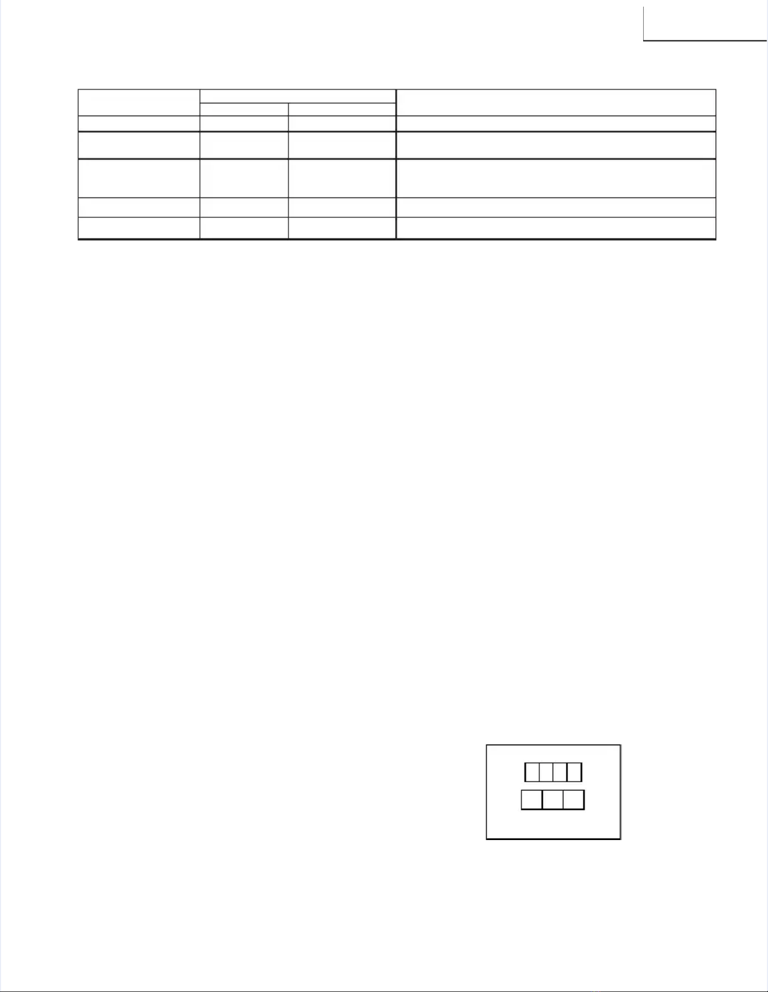
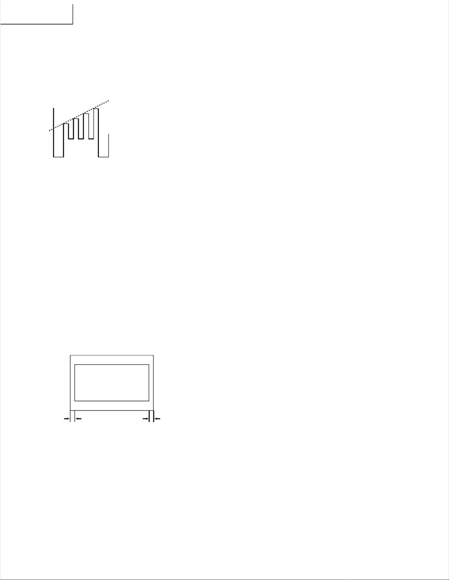
Sub-picture and Sub-Bright AdjustmentsSub-picture and Sub-Bright Adjustments
1.1. ReceivReceive the the wine window pdow patteattern srn signal.ignal.
••RF INPUT (TU51)RF INPUT (TU51)
2.2. Get into Get into servicservice adjuste adjustment dment data "V01ata "V01" and "V05" and "V05" and" and
set the luminance as shown in figure "A" and "B" asset the luminance as shown in figure "A" and "B" as
below below respectivelyrespectively..
••COMPONENT INPUTCOMPONENT INPUT
3.3. Get in serGet in service adjuvice adjustmenstment data "V42t data "V42" and "V45" an" and "V45" andd
set the luminance as shown in figure "A" and "B" asset the luminance as shown in figure "A" and "B" as
below below respectivelyrespectively..
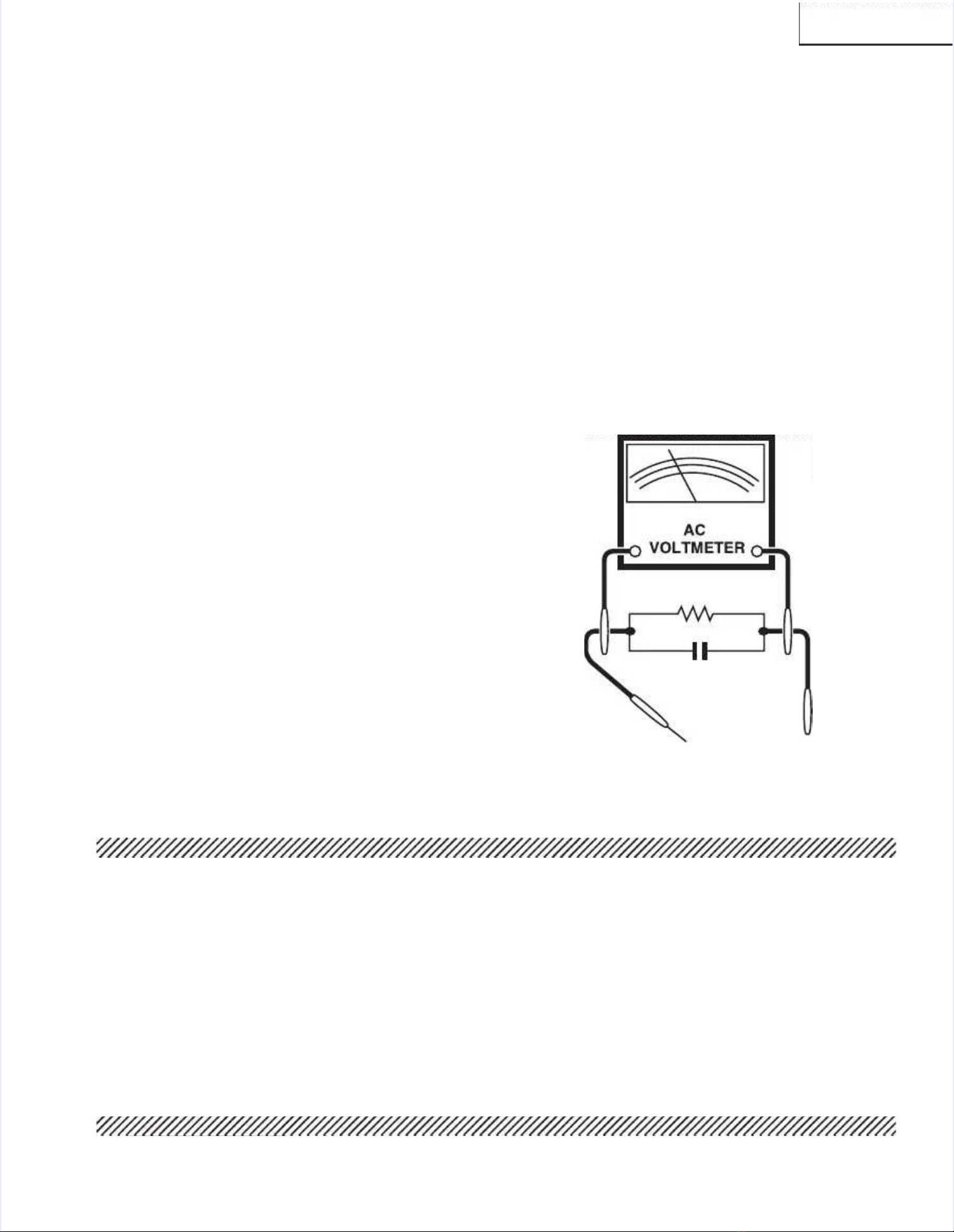
LUMINESCENCE CONLUMINESCENCE CONFIRMAFIRMATIONTION
AA::112200±±10cd/m10cd/m22
BB::11..55±±0.5cd/m0.5cd/m22
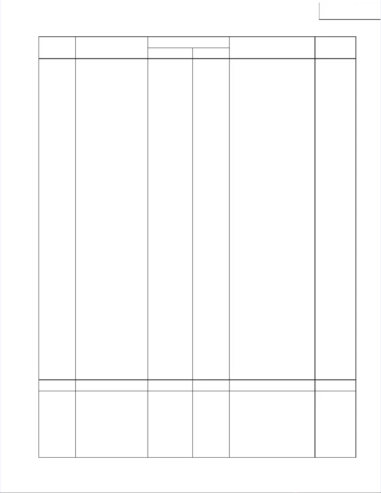
NNEECCEESSSSAARRYYUUNNNNEECCEESSSSAARRYY
ADJUSTMENTADJUSTMENT
PART REPLACEDPART REPLACED
IC2001IC2001
IC201IC201
XXData is stored in IC2101.Data is stored in IC2101.
The adjustment is needed to The adjustment is needed to compensate for characteristics of partscompensate for characteristics of parts
including IC201 and MTS level (M01).including IC201 and MTS level (M01).
Holding down both the VOL-up and Holding down both the VOL-up and CH-up buttons on the TV set at service mode for more than 2 CH-up buttons on the TV set at service mode for more than 2 seconds willseconds will
automatically write the above initial values into IC2101.automatically write the above initial values into IC2101.
NOTESNOTES
XX
IC2101IC2101
IC3001IC3001
CRTCRT
Holding down both the VOL-up and CH-up buttons on the TV set inHolding down both the VOL-up and CH-up buttons on the TV set in
the service mode for more than 2 seconds will automatically write thethe service mode for more than 2 seconds will automatically write the
above initial values into IC2101 Then perform a complete adjustment.above initial values into IC2101 Then perform a complete adjustment.
Adjust items related to Adjust items related to picture tube only.picture tube only.
Adjust items related to MTS only (M01~M20).Adjust items related to MTS only (M01~M20).
XX
XX
XX

10
10
29FL9429FL94
Sub-Tint AdjustmentSub-Tint Adjustment
1.1. Receive Receive the hthe half calf color olor bar sbar signal.ignal.
••RF INPUT (TU51)RF INPUT (TU51)
2.2. Get into Get into YY-Mute by R-Mute by R/C, or by se/C, or by setting thtting the "V1e "V11" bus1" bus
data to "01".data to "01".
3.3. VaVary the ry the "V02" bus "V02" bus data untdata until the wavil the waveform beform becomesecomes
as stated below.as stated below.
Sub-Color AdjustmentSub-Color Adjustment
1.1. RecReceiveive a good le a good locaocal chal channennel.l.
2.2. Make sMake sure thure the custe customer omer color ccolor control ontrol is set is set to cento centerter
position .position .
••RF INPUT (TU51)RF INPUT (TU51)
3.3. Enter tEnter the servhe service modice mode and selee and select servct service adjuice adjustmenstmentt
"V03"."V03".
4.4. Adjust "Adjust "V03" datV03" data value ta value to obtao obtain a normin a normal color al color level.level.
Focus AdjustmentFocus Adjustment
1.1. RecReceiveive a good le a good locaocal chal channennel.l.
2.2. Adjust Adjust the FOCUS the FOCUS VR of thVR of the flybae flyback tranck transformesformer tor to
make the image as fine as possible.make the image as fine as possible.
C. C Display Position AdjustmentC. C Display Position Adjustment
1.1. ReceivReceive the e the lion hlion head pead patterattern sign signal.nal.
2.2. Select Select "EX2" "EX2" to dito display splay the the text text box.box.
3.3. Adjust tAdjust the "EX2" buhe "EX2" bus data to les data to let the tet the text box disxt box displayedplayed
in the center.in the center.
Vertical-Size and Linearity AdjustmentsVertical-Size and Linearity Adjustments
1.1. RecReceiveive a good le a good locaocal chal channennel.l.
(SCREEN FORMAT 4:3)(SCREEN FORMAT 4:3)
2.2. Enter thEnter the service e service mode and mode and select thselect the servicee service
adjustment "D03" for adjustment "D03" for V-size.V-size.
3.3. Adjust tAdjust the "D03" buhe "D03" bus data to ges data to get the propt the proper Ver V-size.-size.
4.4. For VFor V-linearit-linearity adjustmy adjustment, seent, select datlect data bus "D0a bus "D05" and5" and
adjust to get the proper vertical ladjust to get the proper vertical linearityinearity..
(SCREEN FORMAT 16:9)(SCREEN FORMAT 16:9)
5.5. Input daInput data of "Dta of "D22" to mi22" to mines 38 stnes 38 step from ep from "D03” da"D03” data.ta.
(V-SIZE)(V-SIZE)
6.6. Input daInput data of "D24ta of "D24" same as "D0" same as "D05" data. (5" data. (V-LV-LIN)IN)
DISPLAY OF TEXT BOXDISPLAY OF TEXT BOX
TEXT BOXTEXT BOX
AA BB
| A-B | / 2
| A-B | / 2
SPEC INSPECTION:| A-B | / 2SPEC INSPECTION:| A-B | / 2 <<
==5mm5mm
B-AMP Base waveform in stepB-AMP Base waveform in step
(TP47B)(TP47B)
LEVELLEVEL
Note:Note: Aging for 10 min before adjustment. After theAging for 10 min before adjustment. After the
adjustment of V-center and V-size, re-adjustment of V-center and V-size, re-
adjustment for this V-line.adjustment for this V-line.
Vertical Phase AdjustmentVertical Phase Adjustment
(SCREEN FORMAT 4:3)(SCREEN FORMAT 4:3)
1.1. Enter tEnter the serhe service movice mode and inpde and input datut data of “00ha of “00h” on” on
"D01"."D01".
2.2. Adjust "DAdjust "D18" data v18" data value so thaalue so that pictut picture is centre is centered.ered.
(SCREEN FORMAT 16:9)(SCREEN FORMAT 16:9)
3.3. InpInput daut data of "ta of "00h00h" on "D2" on "D20".0".
4.4. Input Input data odata of "D34f "D34" same " same as "D18as "D18" data" data..
Horizontal Position AdjustmentHorizontal Position Adjustment
1.1. RecReceive a geive a good loood local chcal channannel.el.
(SCREEN FORMAT 4:3)(SCREEN FORMAT 4:3)
2.2. Enter thEnter the service e service mode and mode and select thselect the servicee service
adjustment "D02".adjustment "D02".
3.3. Adjust "DAdjust "D02" data v02" data value so thaalue so that pictut picture is centre is centered.ered.
(SCREEN FORMAT 16:9)(SCREEN FORMAT 16:9)
4.4. Input Input data odata of "D21f "D21" same " same as "D02as "D02" data" data..
Horizontal-Size AdjustmentHorizontal-Size Adjustment
1.1. RecReceive a geive a good loood local chcal channannel.el.
(SCREEN FORMAT 4:3)(SCREEN FORMAT 4:3)
2.2. Enter thEnter the service e service mode and mode and select thselect the servicee service
adjustment "D04" for H-size.adjustment "D04" for H-size.
3.3. Adjust tAdjust the "D04" bhe "D04" bus datus data to get ta to get the prophe proper H-sier H-size.ze.
(SCREEN FORMAT 16:9)(SCREEN FORMAT 16:9)
4.4. Input Input data odata of "D23f "D23" same " same as "D04as "D04" data" data..
EW-ParabolaEW-Parabola
1.1. RecReceive a geive a good loood local chcal channannel.el.
(SCREEN FORMAT 4:3)(SCREEN FORMAT 4:3)
2.2. Enter thEnter the service e service mode and mode and select thselect the servicee service
adjustment "D07" for EW parabola.adjustment "D07" for EW parabola.
3.3. Adjust tAdjust the "D07" buhe "D07" bus data ts data to get the o get the proper proper verticalvertical
straight line for both left and right side.straight line for both left and right side.
(SCREEN FORMAT 16:9)(SCREEN FORMAT 16:9)
4.4. Input daInput data of "Dta of "D26" to m26" to mines 21 sines 21 step frotep from "D07" dm "D07" data.ata.
EW-TrapeziumEW-Trapezium
1.1. RecReceive a geive a good loood local chcal channannel.el.
(SCREEN FORMAT 4:3)(SCREEN FORMAT 4:3)
2.2. Enter thEnter the service e service mode and mode and select thselect the servicee service
adjustment "D08" for adjustment "D08" for EW-TrapeziumEW-Trapezium..
3.3. Adjust tAdjust the "D08" bhe "D08" bus data us data to get tto get the best he best positionposition
display.display.
(SCREEN FORMAT 16:9)(SCREEN FORMAT 16:9)
4.4. Input Input data odata of "D27f "D27" same " same as "D08as "D08" data" data..