9
SERVICE
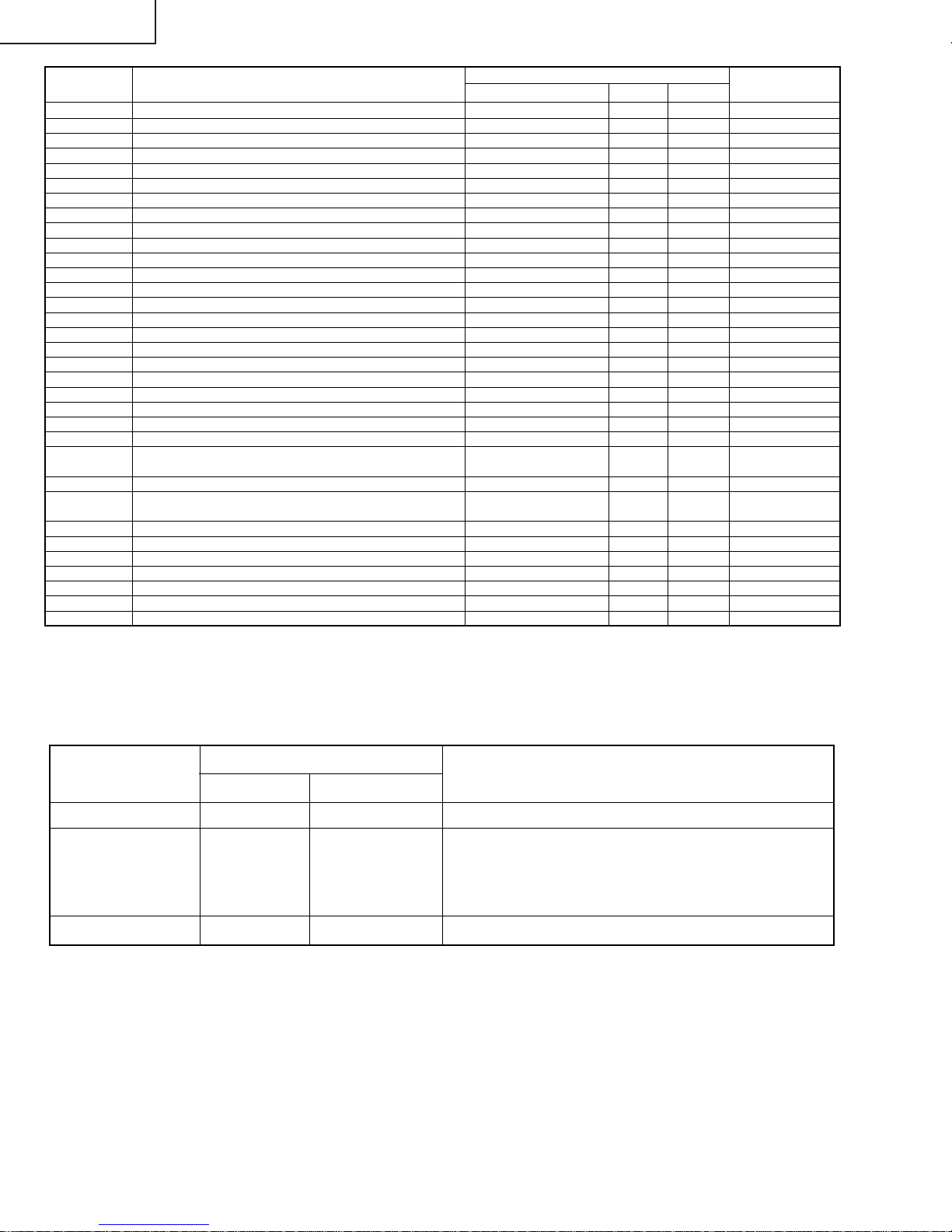
POSITION ADJUST ITEM DATA
RANGE
INITIALVALUE
FIX/ADJ REMARK
AGC AGC TAKE OVER POINT 0~63 14 ADJ
V-LIN VERTICAL SLOPE 0~63 32 ADJ
V-AMP VERTICAL AMP 0~63 32 ADJ
V-CENT VERTICAL SHIFT 0~63 32 ADJ
V-ZOOM VERTICAL ZOOM 0~63 32 FIX
H-CENT HORIZONTAL SHIFT 0~63 32 ADJ
H-SIZE EAST-WEST WIDTH 0~63 32 FIX
EW// HORIZONTAL PARALLELOGRAM 0~63 32 FIX
PARA EAST-WEST PARABOLA / WIDTH 0~63 32 FIX
COR(U) EAST-WEST UPPER CORNER PARABOLA 0~63 32 FIX
COR(L) EAST-WEST LOWER CORNER PARABOLA 0~63 32 FIX
TRAPE EAST-WEST TRAPEZIUM 0~63 32 FIX
HB HORIZONTAL BOW 0~63 32 FIX
S-COR S-CORRECTION 0~63 0 FIX must be "17"
DRI-R-HI “W,P RED OFFSET HIGH / OFFSET BLUE TONE” 0~63 32 FIX must be "32"
DRI-G-HI W.P. GREEN OFFSET HIGH / OFFSET BLUE TONE 0~63 32 FIX must be "33"
DRI-B-HI W.P.BLUE OFFSET HIGH / OFFSET BLUE TONE 0~63 32 FIX must be "37"
DRI-R-MH W.P. RED MH / STD 0~63 25 FIX must be "32"
DRI-G-MH W.P.GREEN MH / STD 0~63 25 ADJ
DRI-B-MH W.P.BLUE MH / STD 0~63 25 ADJ
DRI-R-ML W.P.RED OFFSET ML / OFFSET RED TONE 0~63 32 FIX must be "32"
DRI-G-ML W.P. GREEN OFFSET ML / OFFSET RED TONE 0~63 32 FIX must be "32"
DRI-B-ML W.P. BLUE OFFSET ML / OFFSET RED TONE 0~63 32 FIX must be "25"
DRI-R-LO W.P. RED OFFSET LOW 0~63 32 FIX must be "32"
DRI-G-LO W.P. GREEN OFFSET LOW 0~63 32 FIX must be "22"
DRI-B-LO W.P. BLUE OFFSET LOW 0~63 32 FIX must be "19"
SUB-VOL MAX VOLUME 0~63 63 FIX must be "63"
SUB-CON SUB CONTRAST 0~63 63 FIX must be "54"
SUB-COL SUB COLOUR 0~63 32 ADJ
SUB-BRI SUB BRIGHTNESS 0~63 32 ADJ
SUB-TINT SUB TINT 0~63 32 ADJ
SUB-SHP SUB SHARPNESS 0~63 32 FIX must be "27"
HTL-VOL MAX HOTEL VOLUME 0~63 32 FIX
HTL-PRG HOTEL PROGRAM NO 0~125 or >125 for none 255 FIX
BB-CON BLUE BACK CONTRAST 0~15 10 FIX must be "5"
RGB OSD GRB REFERENCE 0~15 15 FIX must be "5"
CUT-R BLACK LEVEL OFFSET R 0~63 32 ADJ
CUT-G BLACK LEVEL OFFSET G 0~63 32 ADJ
CDL CATHODE DRIVE LEVEL 0~15 0FIX must be "4"
DL-TV Y-D TIME (TV) [YD ] 0~15 12 FIX must be "2"
DL-AV Y-D TIME (AV) [YD ] 0~15 12 FIX must be "8"
INIT INITIAL/DEFAULT LANGUAGE 0(English), 1(Spanish), 0FIX must be "1"
2(French)
FAO-VOL FAO-MAX VOLUME 0~63 63 FIX must be "63"
ESV_OFFS ENERGY SAVE OFFSET 0~63 10 FIX must be "32"
CCPOS CLOSE CAPTION POSITION 0~255 32 ADJ
ATT ATTENUATE INPUT SIGNAL LEVEL 0~15 10 FIX*
BASS BASS LEVEL 0- 15 0FIX must be "8"
TREBLE TREBLE LEVEL 0- 15 0FIX must be "8"
VSD VERTICAL SCAN DISABLE 0 or 1 when item selected 0FIX
BKS BLACK STRETCH 0(disable) or1(enable) 1FIX
AVL AUTOMATIC VOLUME LEVELLING 0(disable) or1(enable) 1FIX
FFI FAST FILTER IF-PLL 0(disable) or1(enable) 0FIX
EVGENABLE VERTICAL GUARD 0(disable) or1(enable) 1FIX must be "0"
EHT EHT TRACKING MODE 0(disable) or1(enable) 1FIX
OSO OVERSCAN SWITCH OFF 0(disable) or1(enable) 0FIX
ACL AUTO COLOUR LIMIT 0(disable) or1(enable) 0FIX must be "1"
FCO FORCED COLOUR-ON 0(disable) or1(enable) 0FIX
VMI VIDEO MUTE AT IDENT LOSS 0(disable) or1(enable) 1FIX
VMC VIDEO MUTE AT PROGRAM/SOURCE CHANGE 0(disable) or1(enable) 1FIX
HTL HOTEL MODE 0(disable) or1(enable) 0FIX
BTSC GAIN FM DEMODULATOR 0(disable) or1(enable) 0FIX
CP CHARGE PUMP 0(fast tuning) or 1 0FIX
(moderate speed tuning)
SERVICE MODE
Table - A
VCO VCO FREE RUNNING FREQUENCY ADJ. 0~63 32 FIX*
FILTER “STEREO, SAP, DBX FILTER ADJ.“0~63 28 FIX*
SPECTRAL STEREO SEPARATION ADJUSTMENT (3kHZ) 0~63 27 FIX*
20MR10M